Project - 2 - Meshing on the suspension Assembly
Modeling and Meshing of Suspension Model
Objective : Modeling and meshing of the suspension model.
Methodology :
1. Import the model onto the ansa gui ( graphic user interface).
2. Check for geometrical errors of the model.
3. The errors on the model are using automatic method or by manual method by using faces module buttons.
4. Model is meahed according to the given quality criteria.
5. Appropriate are made on the model.
PROCEDURE:
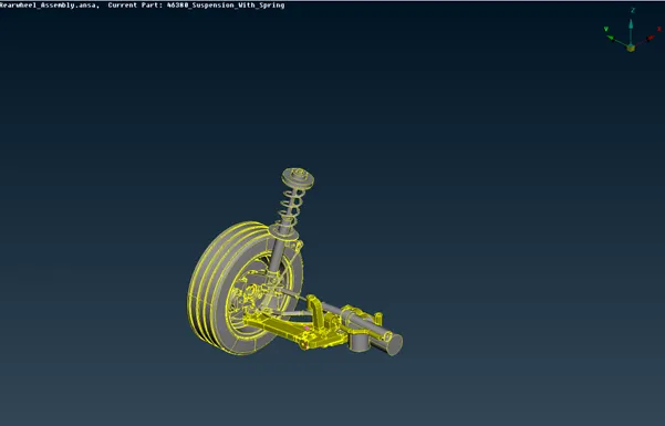
1 . The model is imported onto the ansa gui. It is checked for some geometrical errors. The errors are resolved through automatic or by manual methods.
2. Two types of mesh is deployed on the model.
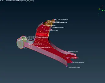
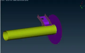
a) Some components of the suspension model has been required to mesh in 2d elements because it has thickness below 5 mm or for uniform thickness.
b) Most of the components are meshed with tria elements.
For the 2D components which are below 5mm thickness the meshing of components is done by the mid surface is extraction manually. The mesh elements are deployed on the mid surface of the components to the given quality criteria.
|
S.No |
Quality Criteria |
|
|
1. |
Target/Average length |
4 |
|
2. |
Minimum Length |
2 |
|
3. |
|
6 |
|
4. |
Aspect |
3 |
|
5. |
Warpage |
15 |
|
6. |
Skewness |
45 |
|
7. |
|
0.7 |
|
8. |
Minimum Quad Angle |
45 |
|
9. |
Maximum Quad Angle |
135 |
|
10. |
Minimum Tria Angle |
30 |
|
11. |
Maximum Tria Angle |
120 |
|
12. |
Tria Percentage |
15 |
The components in the above pictures were meshed using 2D mixed elements.
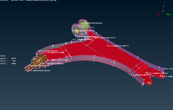
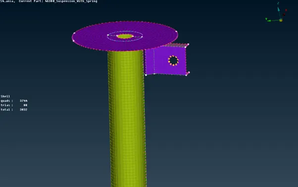
After the components are completely meshed it is checked far any elemental errors and the errors are resolved using Shell mesh Improve module buttons.
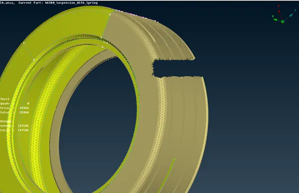
Most of the components are meshed using 3D tria elements because of varying thickness.
The tyre and rim components of the suspension model have separate quality criteria for meshing.
|
S.No |
Quality Criteria |
|
|
1. |
|
6.5 |
|
2. |
Minimum Length |
|
|
3. |
Maximum Length |
|
|
4. |
|
45 |
- The meshing of tyre and rim was done according to the above mentioned quality criteria.
- First tria mesh is deployed on the components according to the quality criteria.
- The tria mesh is then defined manually by using volume mesh module buttons. It creates separate pid since the mesh is being converted from 2D to 3D elements.
- Tetra mesh is done using unstructured mesh module buttons.
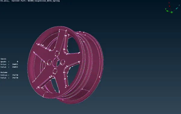
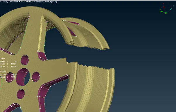
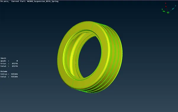
Rest of the components were meshed to this quality criteria :
|
S.No |
Quality Criteria |
|
|
|
1. |
Target/Average length |
4 |
|
|
2. |
|
2 |
|
|
3. |
|
6 |
|
|
4. |
|
45 |
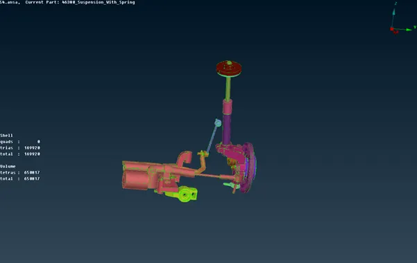
After converting 2D elements to 3D tetra elements , check for tet collapse.
The tet collapse criteria is 0.2 for all the 3D meshed components.
- Tet collapse is one of the quality parameters , which will be checked while generating tetrahedral elements.
- It can be calculated by measuring the distance of a node from the opposite face then each of the 4 values will be divided by the square root of the opposite face’s area.
- This error can be cleared by using reconstruction button under 3D menu page.
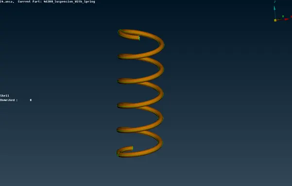
The above suspension spring component was not meshed instead it is represented by 1D pbar elements since it is an NVH model. It is represented by 1D pbar elements using Nastran deck.
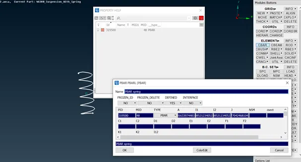
Connection : The suspension model requires some necessary connections as it will be also checked vibrations , so the necessary connections were made using NASTRAN deck module buttons.
- The model is reflected onto the other side using symmetry option.
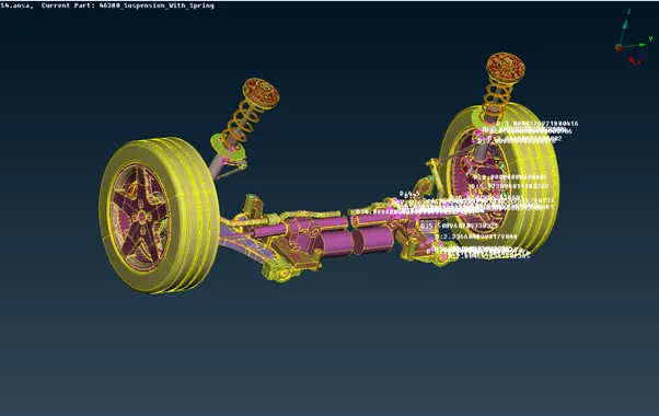
Conclusion : The suspension model was meshed using both 2D and 3D elements and also made necessary connections and reflected onto the other side.
Link :https://drive.google.com/file/d/1eCno_KwvDtb6pJ-he_3b6gFSWsMtOeXR/view?usp=sharing