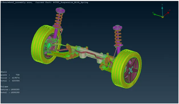
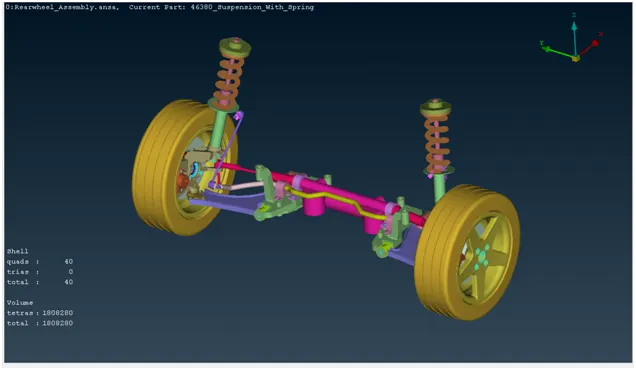
Project - 2 - Meshing on the suspension Assembly
Report
Project Name:
Meshing on the suspension assembly and Also use Appropriate connections to connect the component.
Aim:
For the given assembly, check for the geometrical errors and mesh with the given element Quality criteria. After meshing the component the thickness has to be assigned for mid surfaces. Use tetra elements to model non-uniform thickness components. Also use Appropriate connections to connect the component. At last perform Symmetry command to reflect the half finished model to the other side.
Quality Criteria:
Quality Criteria for Surface Meshing of Tyre and Rim (Element type: Tria) :
|
S.No |
Quality Criteria |
Value |
|
1 |
Target/Average length |
6.5 |
|
2 |
Minimum Length |
5 |
|
3 |
Maximum Length |
10 |
|
4 |
Skewness |
45 |
Quality criteria for Surface Meshing of Non Uniform thickness components other than Tyre and Rim (Element type: Tria) :
|
S.No |
Quality Criteria |
Value |
|
1 |
Target/Average length |
4 |
|
2 |
Minimum Length |
2 |
|
3 |
Maximum Length |
6 |
|
4 |
Skewness |
45 |
Quality Criteria for Volume meshing of all Non Uniform thickness components (Element type: Tetra Elements):
|
S.No |
Quality Criteria |
Value |
|
1 |
Tet-collapse |
0.2 |
Quality criteria for Mid surfacing of Uniform thickness part which has thickness less than 5 mm (Element type: Mixed elements) :
|
S.No |
Quality Criteria |
Value |
|
1 |
Target/Average length |
4 |
|
2 |
Minimum Length |
2 |
|
3 |
Maximum Length |
6 |
|
4 |
Aspect |
3 |
|
5 |
Warpage |
15 |
|
6 |
Skewness |
45 |
|
7 |
Jacobian |
0.7 |
|
8 |
Minimum Quad Angle |
45 |
|
9 |
Maximum Quad Angle |
135 |
|
10 |
Minimum Tria Angle |
30 |
|
11 |
Maximum Tria Angle |
120 |
A] Procedure for Rim and Tyre component:
Quality Criteria:
Quality Criteria for Surface Meshing of Tyre and Rim (Element type: Tria) :
|
S.No |
Quality Criteria |
Value |
|
1 |
Target/Average length |
6.5 |
|
2 |
Minimum Length |
5 |
|
3 |
Maximum Length |
10 |
|
4 |
Skewness |
45 |
Procedure:
following step to be done for meshing the given Rim and Tyre Model.
1] Import:
import the geometry in the .stl,.STEP,.IGES format. (File > Open > Choose the File) and hit on open.
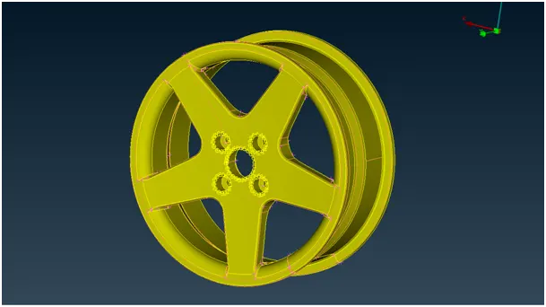
select 1 property ID:
first select the Rim property Id, do the 2D and 3D meshing for this property ID.then select other Tyre property ID and do the same proedure.here i show the procedure for 1st part Rim...
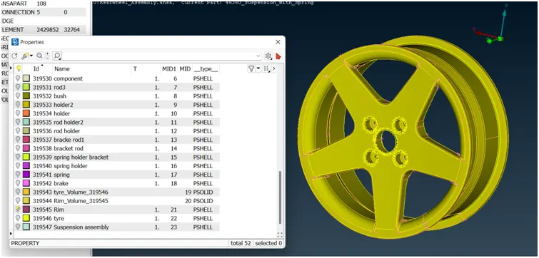
2] Cons resolution:
changing the distance between the nodes(mesh length) from preset value to required value,this will help us to understand the actual shape/ geometry of imported cad model.make sure before meshing this length should be change again to the targeted element length.(mesh module>perimeter>length>1)perimeter2)macros)
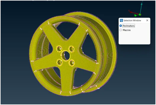
fig 1] before cons resolution:
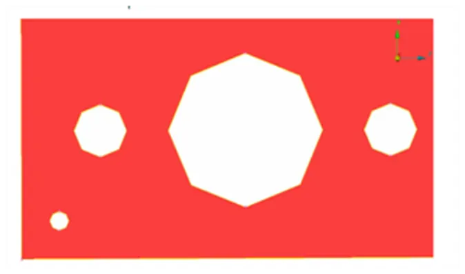
fig 2] after cons resolution:
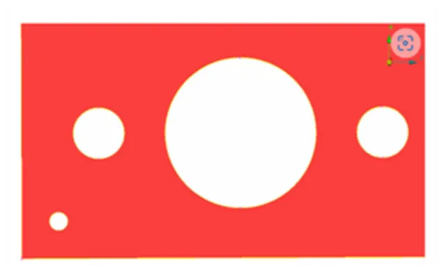
3] Topo option:
- If the imported file it doesn’t have any connectivity between the Surfaces.To get the connectivity between the surfaces we have to use the Topo option.(TOPO Module> Faces > Topo).
- first we check the any single cons are present in the geometry so in focus menu deselect the double cons and press shit+ctrl.
- if any double cons present then use the (TOPO Module> Faces > Topo).
4] orientations:
- We have to Orient the Surfaces to make sure all the surfaces are in one normal direction.(TOPO Module> Faces > Orient)
5] Checking the geometrical errors:
- after the orientations done the we need to check the geometrical error. for that go to (check manager>geometry>execute)
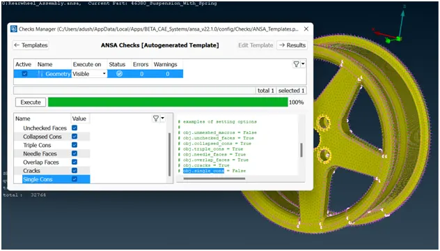
6] Clearing the geometry errors:
if any geometry error is pop out then select the all error and then right click on error and fix them.
7] Check the thickness of the components.
- If the thickness is less than 5 or 6mm then we have to extract the midsurface.
- If the thickness is more than 5 or 6mm then no need to extract the midsurface.
for cheching the thickness of model (isolate>mesure>nodes) or create short cut key for measure option.here is thickness is greater then the 6 mm so we go for solid meshing...
8] Providing the Target element length:
changing the distance between the nodes(mesh length) from preset value to required value,make sure before meshing this length should be change again to the targeted element length.(mesh module>perimeter>length>1)perimeter2)macros)
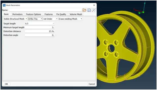
10] Providing the Mesh Parameters.
based on the given data we provide the target element length is 1mm,minmum target length is 0.5 mm,and maximum target length is 2mm etc...
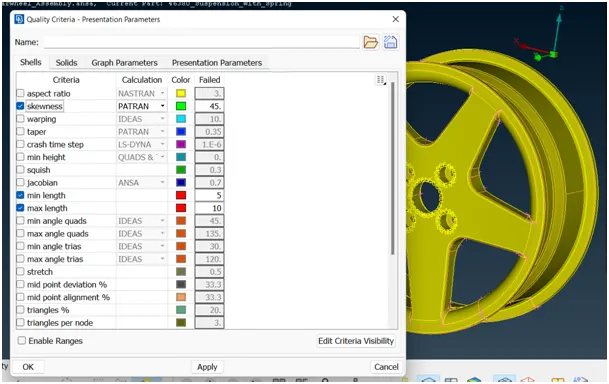
11] Providing 2D Quality criteria to the models:
based on the given data we provide the Quality criteria to the models.
12] Geometry cleanup:
for geometry cleanup i use some feature likes:
1] topo module>faces>Datch
2] topo module>faces>cut
3] topo module>cons>release
4] topo module>hot points>insert/delete
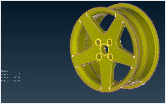
13] Generating the 2D Mesh:
for creating the mesh we use the lot of command but i explain some of them.
creating the mesh: (mesh module>mesh generation>best)
- for curved surface: (option list> element type>ortho tria)
- for plane surface: (option list> element type> tria)
smothning the mesh:(mesh module>shell mesh>smooth)
reconstruct the mesh:(mesh module>shell mesh>reconst)
improve the quality of mesh:(mesh module>elements>split/swap/join/stich)
insert or delete hot points:(mesh module>hot points>insert/delete)
to increae or decrease elements number:(mesh module>perimeters>NUM+/-)
to cut or join the face:(mesh module>macro>cut/join)
to delete the mesh:(mesh module >mesh generation>erase)
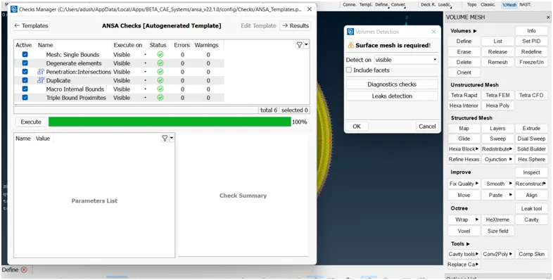
14] pre- volume check and volume defination:
here i define the pre-volume check and create the seperate volume property for each part/property (v.mesh>volumes>define>auto detect>visible>run)
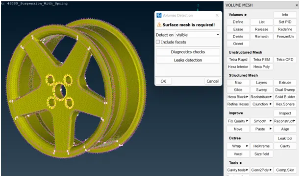
Diagonastics check:
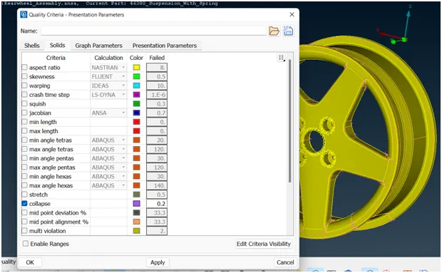
15] Providing 3D Quality criteria to the models:
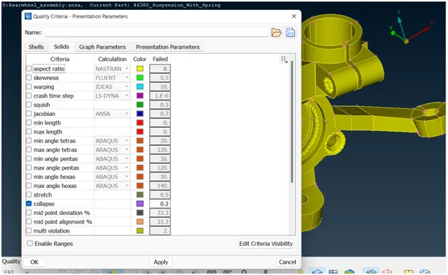
based on the given quality criteria i put the correspomding value in quality criteria.(quality criteria>solid>put data>apply>ok)
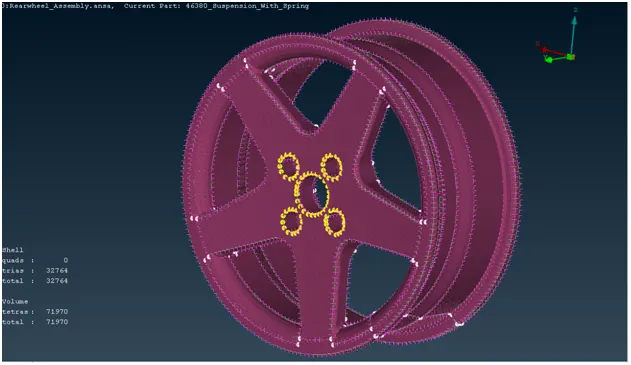
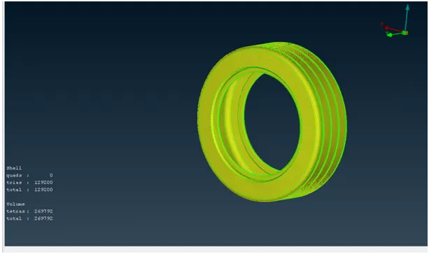
16] Generating the 3D Mesh:
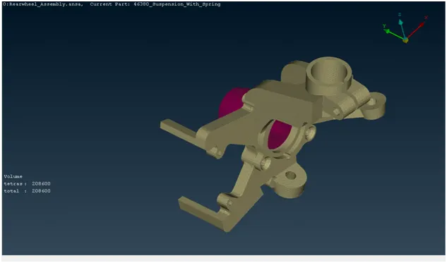
for generating the 3D mesh i use the below process:(volume mesh>unstructured mesh>tetra rapid>volume>select geometry).and doing some changes in option list.
1] Rim:
2] Tyre:
B] Procedure for Surface Meshing of Non Uniform thickness components other than Tyre and Rim component:
there is so many component in the suspension assemble which is under this criteria,so i explain one component here and do the same process for other components.
Quality criteria for Surface Meshing of Non Uniform thickness components other than Tyre and Rim (Element type: Tria) :
|
S.No |
Quality Criteria |
Value |
|
1 |
Target/Average length |
4 |
|
2 |
Minimum Length |
2 |
|
3 |
Maximum Length |
6 |
|
4 |
Skewness |
45 |
Procedure:
following step to be done for meshing the given brake pedal holder.
1] Import:
import the geometry in the .stl,.STEP,.IGES format. (File > Open > Choose the File) and hit on open.
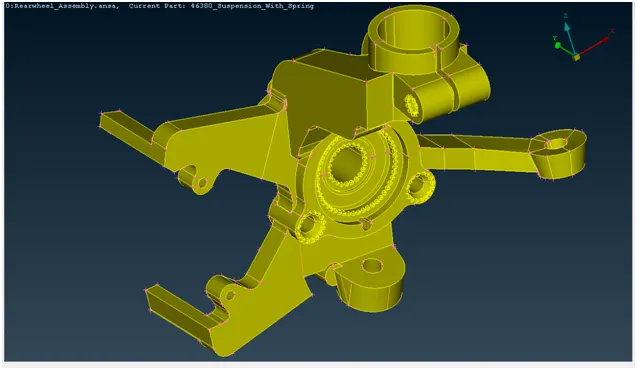
select 1 property ID:
first select the Rim property Id, do the 2D and 3D meshing for this property ID.then select other Tyre property ID and do the same proedure.here i show the procedure for 1st part Rim...
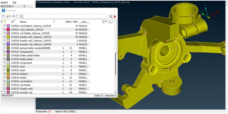
2] Cons resolution:
changing the distance between the nodes(mesh length) from preset value to required value,this will help us to understand the actual shape/ geometry of imported cad model.make sure before meshing this length should be change again to the targeted element length.(mesh module>perimeter>length>1)perimeter2)macros)
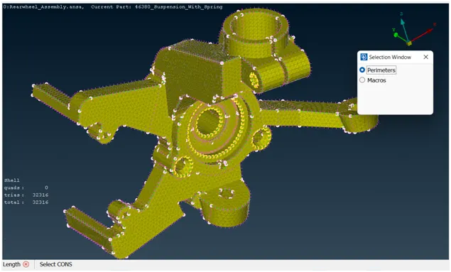
fig 1] before cons resolution:
fig 2] after cons resolution:
3] Topo option:
- If the imported file it doesn’t have any connectivity between the Surfaces.To get the connectivity between the surfaces we have to use the Topo option.(TOPO Module> Faces > Topo).
- first we check the any single cons are present in the geometry so in focus menu deselect the double cons and press shit+ctrl.
- if any double cons present then use the (TOPO Module> Faces > Topo).
4] orientations:
- We have to Orient the Surfaces to make sure all the surfaces are in one normal direction.(TOPO Module> Faces > Orient)
5] Checking the geometrical errors:
- after the orientations done the we need to check the geometrical error. for that go to (check manager>geometry>execute)
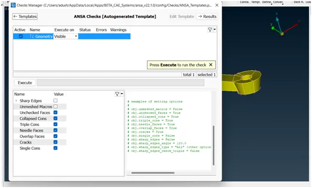
6] Clearing the geometry errors:
if any geometry error is pop out then select the all error and then right click on error and fix them.
7] Check the thickness of the components.
- If the thickness is less than 5 or 6mm then we have to extract the midsurface.
- If the thickness is more than 5 or 6mm then no need to extract the midsurface.
for cheching the thickness of model (isolate>mesure>nodes) or create short cut key for measure option.here is thickness is greater then the 6 mm so we go for solid meshing...
8] Providing the Target element length:
changing the distance between the nodes(mesh length) from preset value to required value,make sure before meshing this length should be change again to the targeted element length.(mesh module>perimeter>length>1)perimeter2)macros)
10] Providing the Mesh Parameters.
based on the given data we provide the target element length is 1mm,minmum target length is 0.5 mm,and maximum target length is 2mm etc...
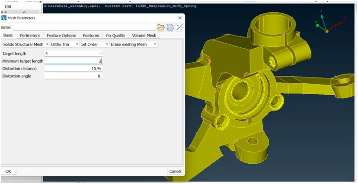
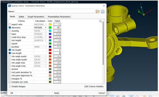
11] Providing 2D Quality criteria to the models:
based on the given data we provide the Quality criteria to the models.
12] Geometry cleanup:
for geometry cleanup i use some feature likes:
1] topo module>faces>Datch
2] topo module>faces>cut
3] topo module>cons>release
4] topo module>hot points>insert/delete
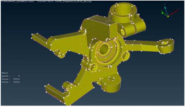
13] Generating the 2D Mesh:
for creating the mesh we use the lot of command but i explain some of them.
creating the mesh: (mesh module>mesh generation>best)
- for curved surface: (option list> element type>ortho tria)
- for plane surface: (option list> element type> tria)
smothning the mesh:(mesh module>shell mesh>smooth)
reconstruct the mesh:(mesh module>shell mesh>reconst)
improve the quality of mesh:(mesh module>elements>split/swap/join/stich)
insert or delete hot points:(mesh module>hot points>insert/delete)
to increae or decrease elements number:(mesh module>perimeters>NUM+/-)
to cut or join the face:(mesh module>macro>cut/join)
to delete the mesh:(mesh module >mesh generation>erase)
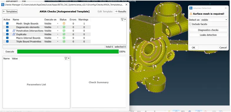
14] pre- volume check and volume defination:
here i define the pre-volume check and create the seperate volume property for each part/property (v.mesh>volumes>define>auto detect>visible>run)
Diagonastics check:
15] Providing 3D Quality criteria to the models:
based on the given quality criteria i put the correspomding value in quality criteria.(quality criteria>solid>put data>apply>ok)
16] Generating the 3D Mesh:
for generating the 3D mesh i use the below process:(volume mesh>unstructured mesh>tetra rapid>volume>select geometry).and doing some changes in option list.
C] Meshing Mid surfacing of Uniform thickness part which has thickness less than 5 mm:
Quality criteria:
Quality criteria for Mid surfacing of Uniform thickness part which has thickness less than 5 mm (Element type: Mixed elements) :
|
S.No |
Quality Criteria |
Value |
|
1 |
Target/Average length |
4 |
|
2 |
Minimum Length |
2 |
|
3 |
Maximum Length |
6 |
|
4 |
Aspect |
3 |
|
5 |
Warpage |
15 |
|
6 |
Skewness |
45 |
|
7 |
Jacobian |
0.7 |
|
8 |
Minimum Quad Angle |
45 |
|
9 |
Maximum Quad Angle |
135 |
|
10 |
Minimum Tria Angle |
30 |
|
11 |
Maximum Tria Angle |
120 |
Procedure:
following step to be done for meshing the given Model.
1] Import:
import the geometry in the .stl,.STEP,.IGES format. File > Open > Choose the File and hit on open.
2] Cons resolution:
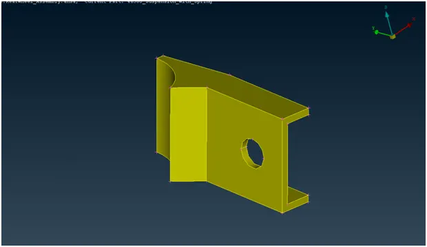
changing the distance between the nodes(mesh length) from preset value to required value,this will help us to understand the actual shape/ geometry of imported cad model.make sure before meshing this length should be change again to the targeted element length.(mesh module>perimeter>length>1)perimeter2)macros)
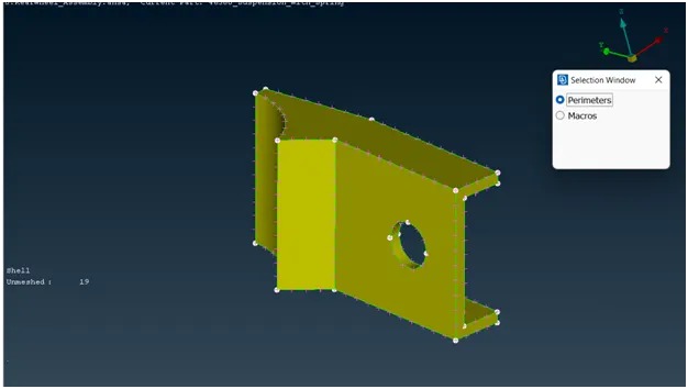
fig 1] before cons resolution:
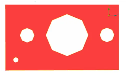
fig 2] after cons resolution:
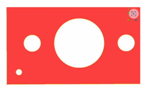
3] Topo option:
- If the imported file it doesn’t have any connectivity between the Surfaces.To get the connectivity between the surfaces we have to use the Topo option.(TOPO Module> Faces > Topo).
- first we check the any single cons are present in the geometry so in focus menu deselect the double cons and press shit+ctrl.
- if any double cons present then use the (TOPO Module> Faces > Topo).
4] orientations:
- We have to Orient the Surfaces to make sure all the surfaces are in one normal direction.(TOPO Module> Faces > Orient)
5] Checking the geometrical errors:
after the orientations done the we need to check the geometrical error. for that go to (check manager>geometry>execute)
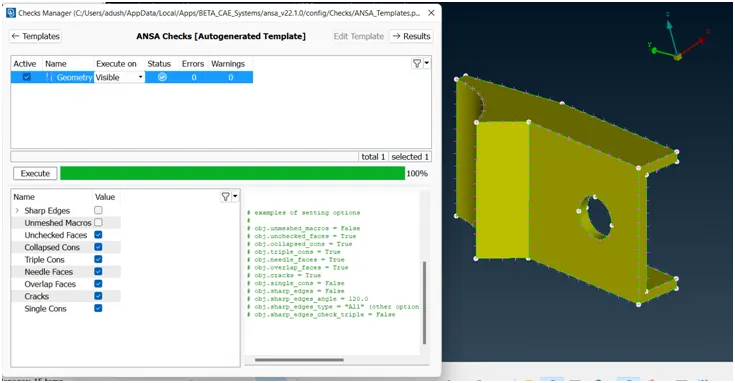
6] Clearing the geometry errors:
if any geometry error is pop out then select the all error and then right click on error and fix them.
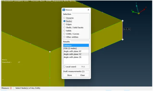
7] Check the thickness of the components.
- If the thickness is less than 5 or 6mm then we have to extract the midsurface.
- If the thickness is more than 5 or 6mm then no need to extract the midsurface.
for cheching the thickness of model (isolate>mesure>nodes) or create short cut key for measure option.
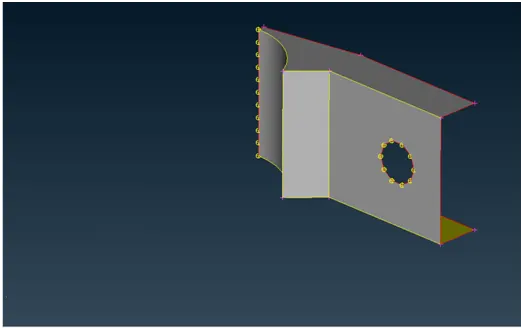
8] Creating the midsurface for a sheet metal Component.
- If the components have the uniform thickness then we will be using the Skin or Offset options to extract the midsurface.
- If we are using the skin method make sure that unchecking of Delete original surfaces in the options list.(topo module>faces>mid surface>skin/casting)
- If we are using the Offset option, we will be using the feature selection to get the mid surface in an easier manner. While providing the offset value we have to make a change in the options list from use existing to auto create for the property.(topo module>faces>offset)
9] Providing the Target element length:
changing the distance between the nodes(mesh length) from preset value to required value,make sure before meshing this length should be change again to the targeted element length.(mesh module>perimeter>length>1)perimeter2)macros)
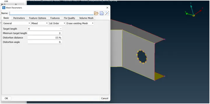
10] Providing the Mesh Parameters.
based on the given data we provide the target element length is 4mm,minmum target length is 2 mm,and maximum target length is 6mm etc
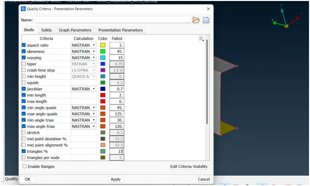
11] Providing Quality criteria to the models:
based on the given data we provide the Quality criteria to the models.
12] Cleaning the Midsurface extracted:
- If there are any unnecessary hotpoits we will be using the Delete option in Hotpoints group to avoid or we can use the insert option with right mouse click.(topo module>hot points>insert/delete)
- If there are any construction lines which will affect the mesh flow we will avoid them.(topo module>face>cut)
- If there are any two feature lines which are very near to each other and the distance between them is less than your minimum then you will be suppressing any one of the line.(topo module>face>cut)
- Feature Line:- We call a double con as a feature line when the surface after that double has significance change(Flat surface may be attached to a curved surface or viceversa) in the geometry.
14] Generating the Mesh:
for creating the mesh we use the lot of command but i explain some of them.
creating the mesh: (mesh module>mesh generation>best)
smothning the mesh:(mesh module>shell mesh>smooth)
reconstruct the mesh:(mesh module>shell mesh>reconst)
improve the quality of mesh:(mesh module>elements>split/swap/join/stich)
insert or delete hot points:(mesh module>hot points>insert/delete)
to increae or decrease elements number:(mesh module>perimeters>NUM+/-)
to cut or join the face:(mesh module>macro>cut/join)
to delete the mesh:(mesh module >mesh generation>erase)
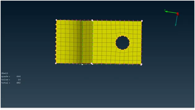
15] Assign the thickness:
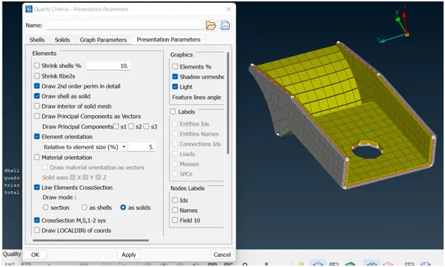
Assign the proper thickness for the newly created midsurface so that (quality criteria>presentation parameters>check the draw shell as solid)
16] check the whole model for Quality criteria:
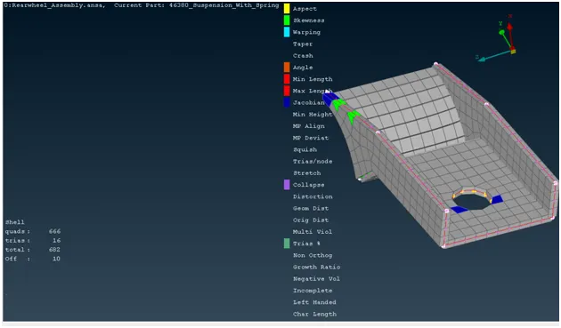
here its showing the out of total 682 mesh elements 10 elements are OFF(failling in Quality criteria)
Providing the Connection:
1] Seam weld:
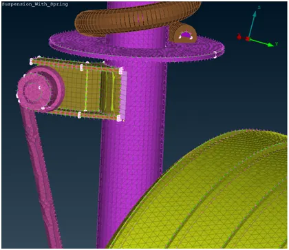
- We have to create a curve by using the feature2 curve(Mesh>Perimeters>Feat2Curve) option.
- We have to convert the curve to a seam line.
- We have to use the connection manager and we have to select it.
- We have to select the PID’s(P1,P2)
- Fe representation - Overlap Shell (For Parallel Surfaces)
- We have to provide the Search distance.
- We have to choose the Proper base sheet.
- We have to provide the width value as the target element size.
- We have to create the weld pid.
2] bolt connection:
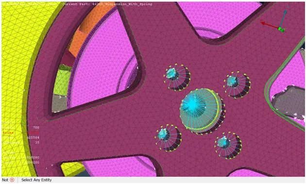
- We have to create a 3d point.
- We have to convert the 3D point to a bolt.
- We have to use the connection manager and we have to select it.
- We have to select the PID’s(P1,P2etc..)
- Fe representation - Bolt
- We have to provide the Search distance.
- Say apply and realize it.
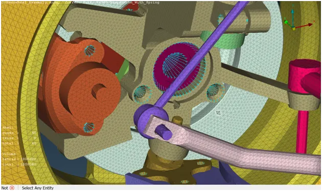
Total Suspension Assembly: