Project - 2 - Meshing on the suspension Assembly
Aim: Meshing on the suspension Assembly
Introduction:
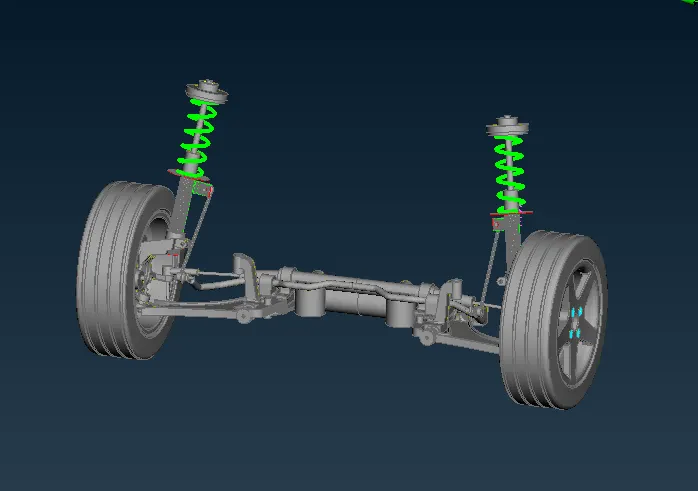
Suspension Assembly: The suspension system's primary function is to maximize the overall performance of a vehicle as it cruises down the road. The suspension system also helps to absorb bumps in the road and provide a safe and comfortable ride. In this project we work on the meshing on the suspension assembly system.
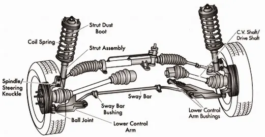
Car Suspension System
While meshing, we have to take care for the following things:
- Use Volume mesh for Tyre and Rim with below Quality criteria. (Use Tria Element)
- Use mid surface only when the thickness is uniform and less than 5 mm. (Use Mixed elements
Only half the model is given in project. We have to mesh on this half and then mirror it to get the other half.
Procedure:
1. First set resolution to 1 mm.
Go to Mesh Module> Perimeters >> Length >> select preimeter>>select complete model>> give length 1 mm >> click ok
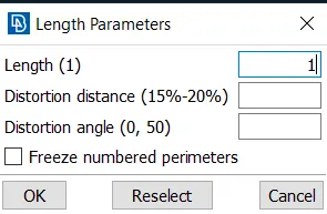
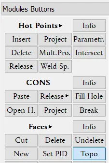
2. Now connect the cons by performing Topo Operation.
Goto Topo Module>> Faces>> Topo>> seect the all componant and click ok.
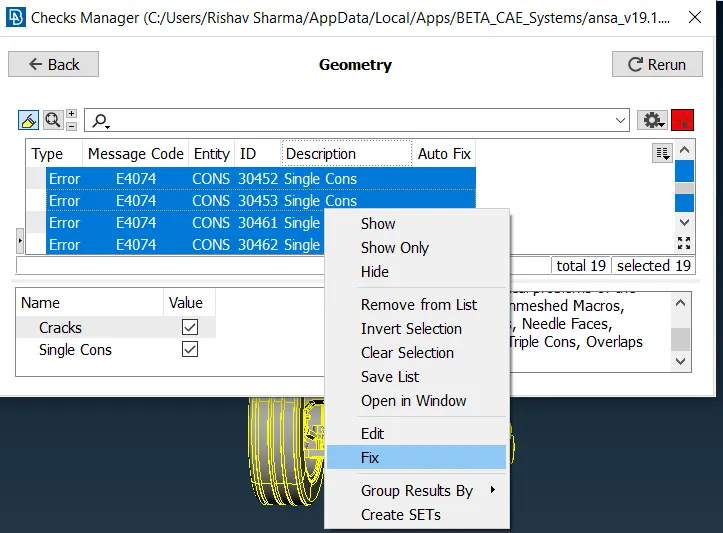
3. Go to check Geometry and clear all the geometry error. Try to auto fix the errors and if error does not fix do it manualy.
Select all the errors >> right click >> Select fix
4. Seperate the different components in different PIDs.
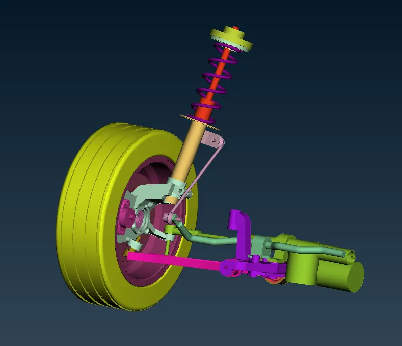
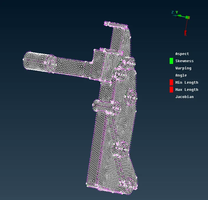
5. Now Extract the mid Surface for constant thickness part (less than 5 mm) and Mesh on the Mid Surface. Here I use offset method to extract mid surface because the thickness of part is constant. And then Mesh it. Check the quality parameter as well.
Quality criteria for Mid surfacing of Uniform thickness part which has thickness less than 5 mm (Element type: Mixed elements) :
|
S.No |
Quality Criteria |
Value |
|
1 |
Target/Average length |
4 |
|
2 |
Minimum Length |
2 |
|
3 |
Maximum Length |
6 |
|
4 |
Aspect |
3 |
|
5 |
Warpage |
15 |
|
6 |
Skewness |
45 |
|
7 |
Jacobian |
0.7 |
|
8 |
Minimum Quad Angle |
45 |
|
9 |
Maximum Quad Angle |
135 |
|
10 |
Minimum Tria Angle |
30 |
|
11 |
Maximum Tria Angle |
120 |
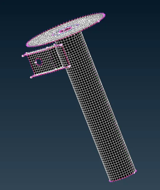
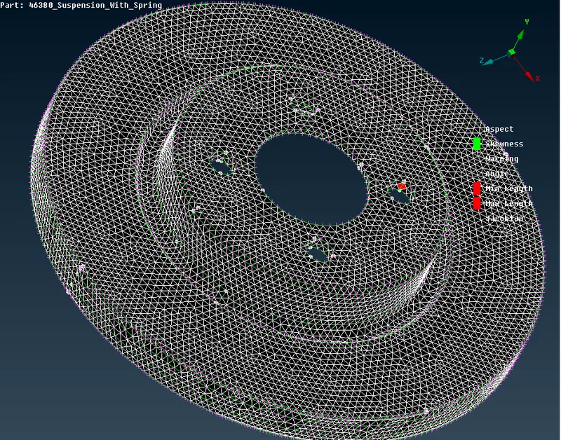
6. Now perform surface meshing for Tyre and Rim part.
Quality Criteria for Surface Meshing of Tyre and Rim (Element type: Tria) :
|
S.No |
Quality Criteria |
Value |
|
1 |
Target/Average length |
6.5 |
|
2 |
Minimum Length |
5 |
|
3 |
Maximum Length |
10 |
|
4 |
Skewness |
45 |
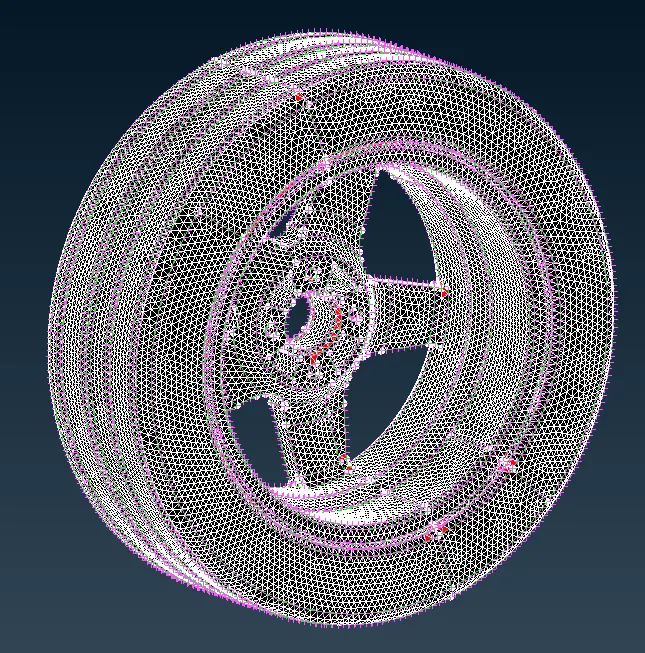
Surface meshing on Tyre and Rim
7. Similary do the surface meshing on the other parts which have non uniform thickness (more than 5 mm)
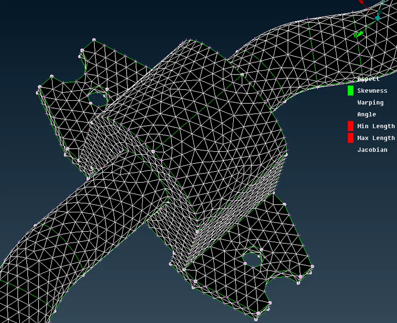
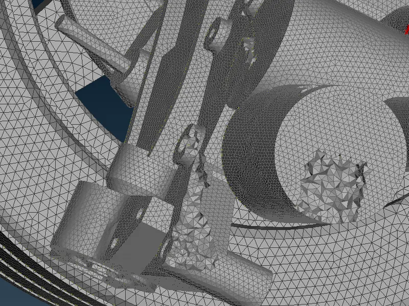
8. Now perform Volume Mesh on the required parts. Follow the following steps:
A. Go to the Volume deck and define the volume for the closed mesh.
B. After defining the volume go to the lists and edit the volume by changing the type to tetra rapid.
C. Remesh the volume.
D. Check for the Tet collapse and fix the Tet collapse.
9. Now give required connections:
Connections: The term, connections or assembly involves various actions that will finally lead to the creation of an inter - connected structure.
Generally, Process of connection is divided into two parts:
1. First create a ANSA entities, containing information such as types, position, parts to connected and geometry.
2. Realized (Convert to FE representation) already created entities.
Types of Connections:
1. Rigid
a) RBE2 (two node and multi node)
b) RBE3 (two node and multi node)
2. Seam Weld
a) Y joint weld : For perpendicular surfaces
b) Overlap weld : For parallel serfaeces
3. Cbush Element: Use to lock air, water
4. Spot weld
5. Bolt
Seam weld Connection:
- We have to create a curve by using the feature2 curve(Mesh>Perimeters>Feat2Curve) option.
- We have to convert the curve to a seam line.
- We have to use the connection manager and we have to select it.
- We have to select the PID’s(P1,P2)
- Fe representation - Overlap Shell (For Parallel Surfaces) or Y-joint Shell ( For Perpendicular Surfaces)
- We have to provide the Search distance.
- We have to choose the Proper base sheet.
- We have to provide the width value as the target element size.
- We have to create the weld pid.
- Say apply and realize it.
Bolt Connection:
1. We have to create a 3d point.
2. We have to convert the 3D point to a bolt.
3. We have to use the connection manager and we have to select it.
4. We have to select the PID’s(P1,P2etc..)
5. Fe representation - Bolt
6. We have to provide the Search distance.
7. Say apply and realize it.
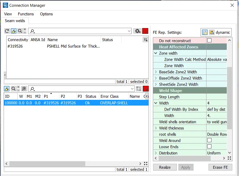
Connection Manager for SeamWeld
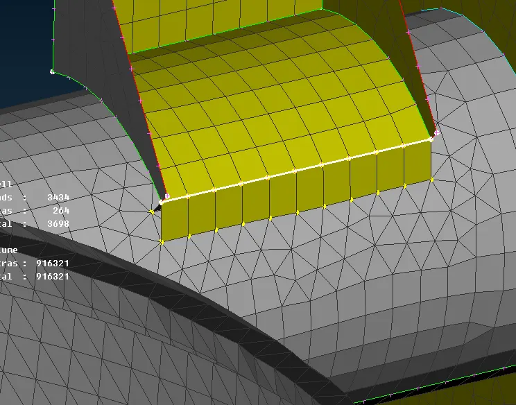
Seam Weld
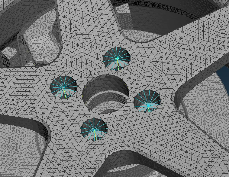
RBE2 Rigid Bolt Connectio n
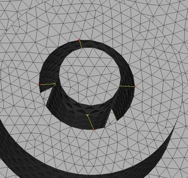
2 node rbe2 constraints
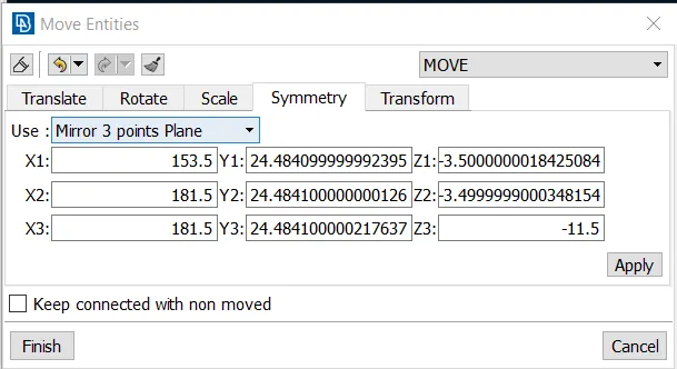
10. At last we perform symmetry Symmetry command to reflect the half finished model to the other side.
Conclusion: Thus we mid surface extracting and meshing, surface meshing and volume meshing. All the necessary connections ar deployed sucessesfully to constrained the model.
Project Link: https://drive.google.com/drive/folders/1qRG9qiKOmxoFm6gnpkhprTMi4K9xh_cH?usp=sharing