Project - 2 - Meshing on the suspension Assembly
Aim : To visualize mesh for the given component car suspension system using ANSA.
Procedure :
- check the geomentical errors in CHECKS MANAGER and fix them manually.
- try to measure the thickness and set PID for those regions.so,that meshing can be done based up on the PID setup.
- If the thickness is less than 5mm and uniform take mis surfa ce and mesh for those region.
step :1
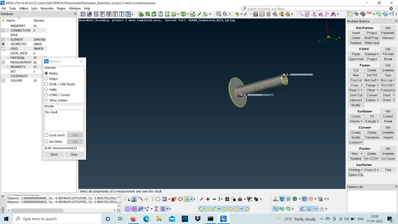
use measure option and check the thickness the coil spring lower insulator and the bracket connected to the pendulum bar willbe less than 5mm.so,take mid-surface for those parts.
step :2
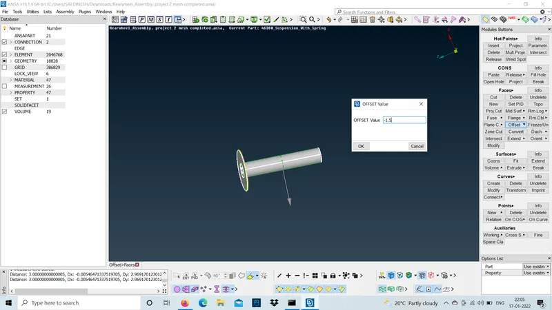
use offset method and take the mid-surface for the spring lower insulator.
step :3
now,set the quality criteria for the given shell element and use mixed mesh to mesh the part.
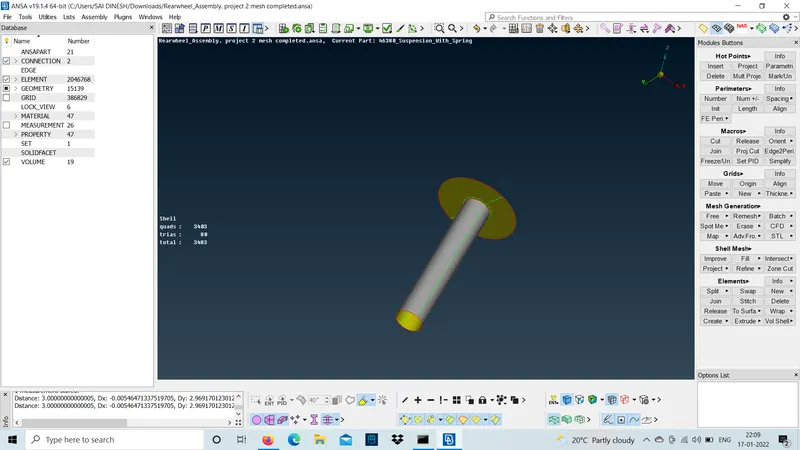
similarly,do the same for the pendulum bracket and mesh the part.
- The entire suspension is divided into 21 PIDS they are:-
- PIDs can be done using set PID with PID region and select the cross hatches the entire area with same thickness will be captured.
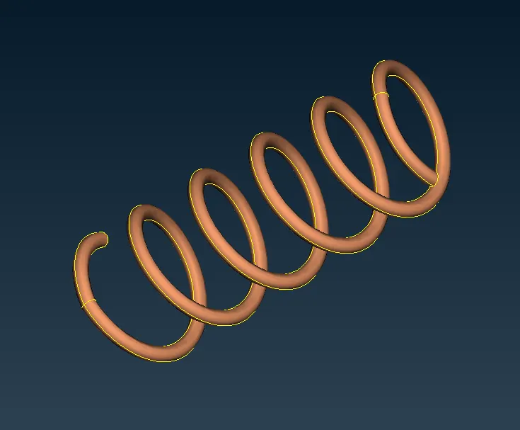
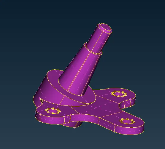
1. strut mount. 2. coil spring upper plate. 3.coil spring.
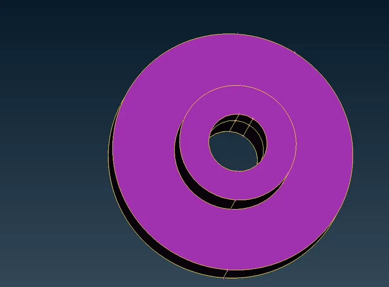
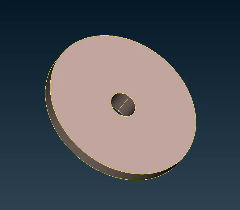
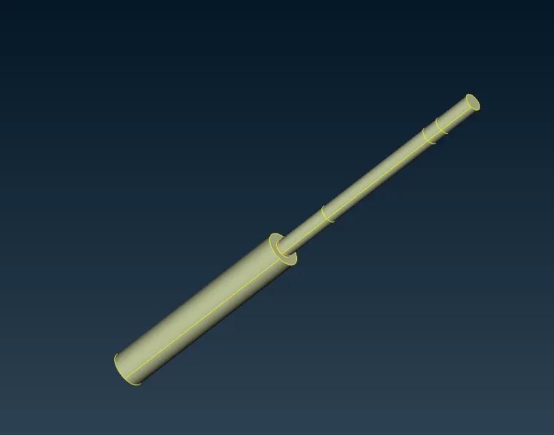
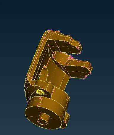
4.coil spring lower insulator. 5.shock obsorber. 6. shock obsorber cylinder joint.
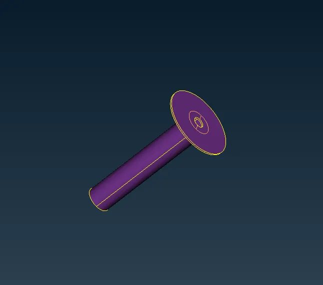
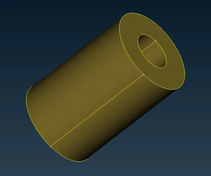
7.steering krunckle. 8.wheel hub. 9. rotor wheel disk.
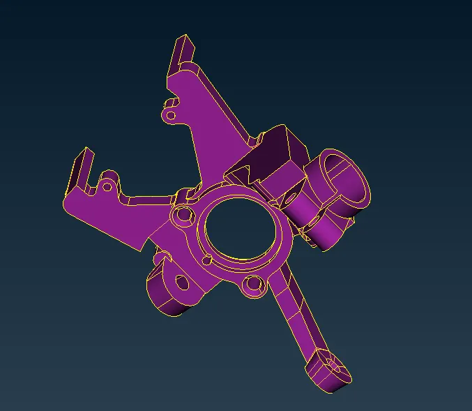
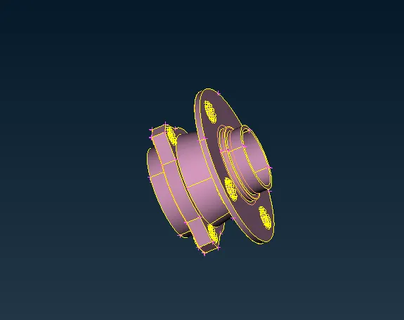
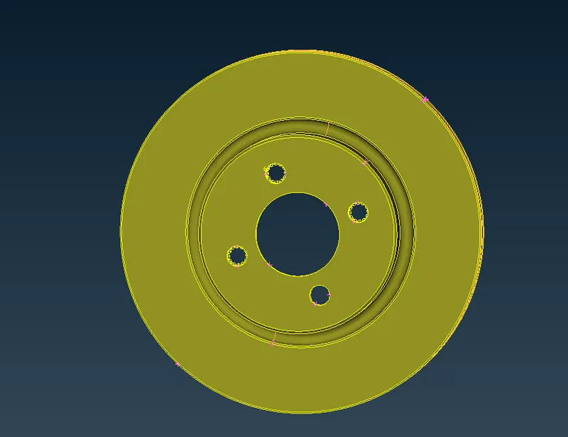
10.Tie rod 11.chassis part. 12.wishbone.
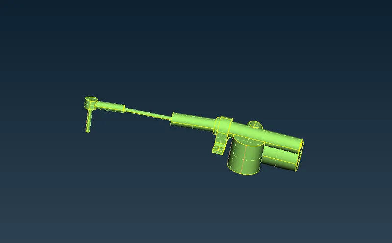
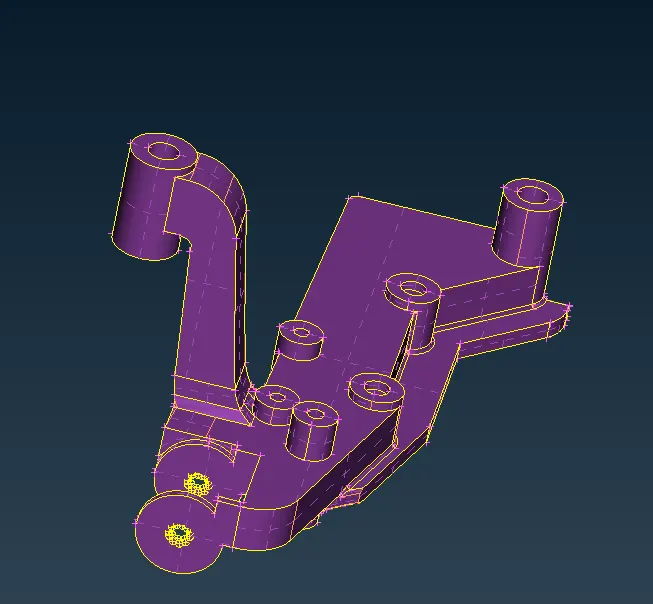
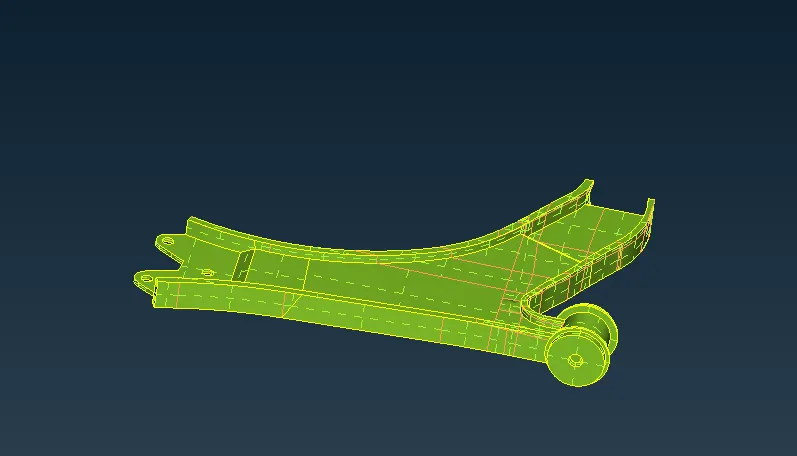
13.sway bar. 14.ball joint. 15.brake calliper.
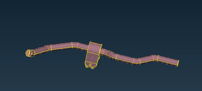
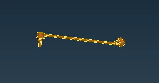
16. pendulum bar. 17.Rim. 18.Tyre
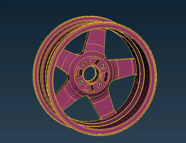
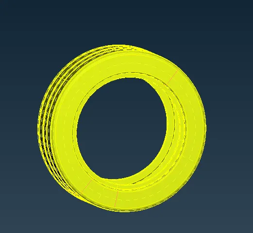
- This PID will split the entire suspension into separate parts.so,that we can select the particular component and mesh that part.
- now shift from topo mode to mesh mode and set the quality criteria for the shell elememts.
- For,3D part the element type should be ortho tria and tria mesh should be diployed.
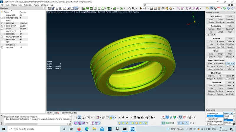
- while meshing a 3D model the elements will be failing for quality.so,try to cut it and mesh the area to avoid max failing of elements.
- the feature area should not be distrubed to achieve a proper mesh flow.
- Initially,we can't understand to proceed with ortho tria or tria mesh should be diployed at particular area .we can understand it totally based up on experience of using the tool.
step :1
use ortho tria mesh at bolt regions to achieve a proper mesh flow at those areas.becuase when we diploy connections at those bolt areas it will be captured properly with proper nodal points.
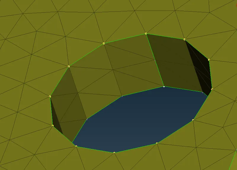
STEP :2
Tria mesh should be diployed at falt regions. beacuse,in tria mesh the forming of elements will be less than ortho tria.
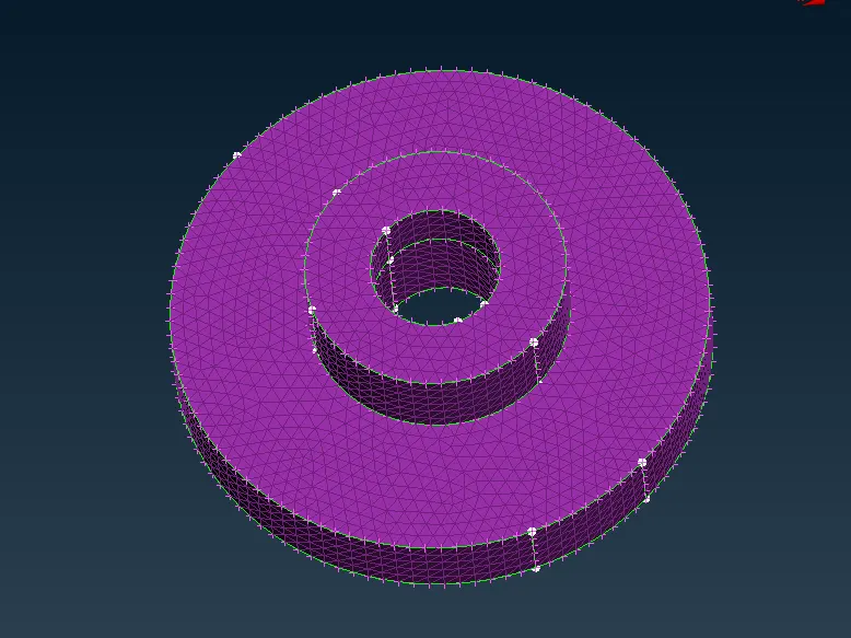
- for,the coil solid spring we should diploy a 1D CBAR elememts .
step 1 :-
generate a middle curve for the spring by using the middle option in the curves.
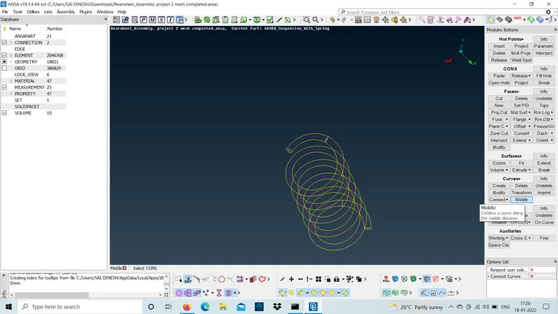
step 2:-
connect the curve into a single curve.By using the connect(multi)option in curves.
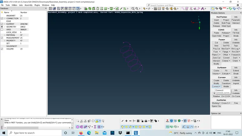
step 3:-
create a COG point for the curves to define the orientation.
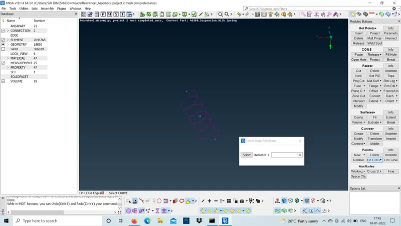
step 4:-
shift to NASTRAN deck and select the CBAR element.
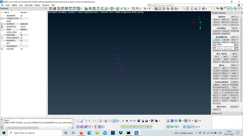
step 5:-
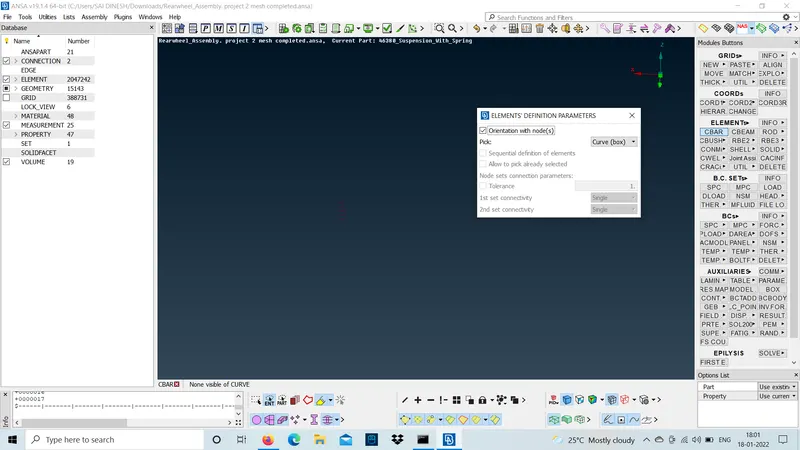
change the selection type to curve(box).
step 6:-
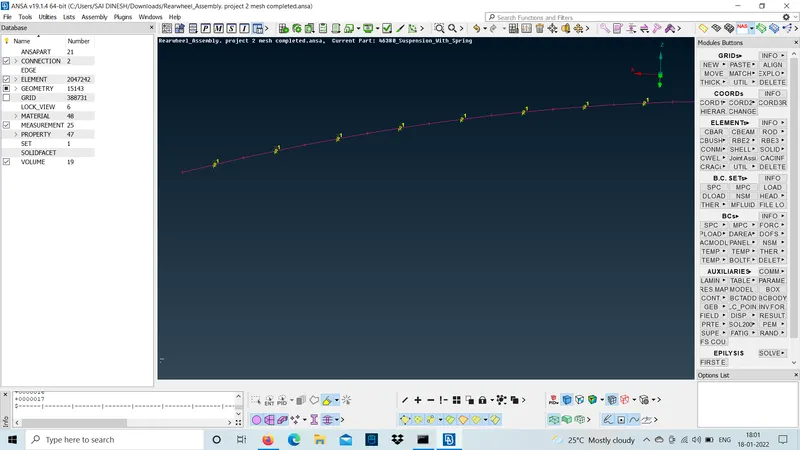
now select the curve and middle mose click and slect the orientation node and specify the elememt lenght as 3mm and middle mouse click and define a new PID .now difine the radius of the spring as 5mm it will calculate the cross cross section area and momemt of inertia.
step 7:-
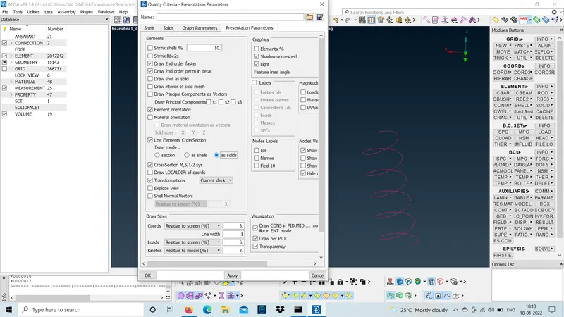
To see the representation of the 1D bar element as 3D (solids).check the box of 1D detailed representation with the solid in quality parameters.
step 8 :-
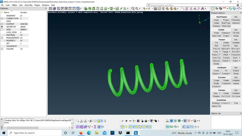
clickmon apply and ok .The 1D bar element will be represented as solid element.
- volume mesh for the non -uniform thickness components should be represented.
volume mesh should be done by using tetra elements with the given solid quality criteria.volume mesh is used to fill the hollow gap inside with tetra elements as a solid part and almost the tet-collapse value will be given .
- There are 2 types of tetra mesh to diploy a volume mesh they are:-
- Tetra Rapid : This will represent a volume mesh and it will not follow the path of the shell mesh and only fill the gap with tetra elements and it takes less time to diploy as well.
- Tetra FEM : This will represent a volume mesh and it will follow the path of the shell mesh up to 2 or 3 layers nad fill the gap with tetra elemnts and also it takes more time than tetra rapid.
step 1 :-
use define option under volumes and define the solid PID as (PSOLID).
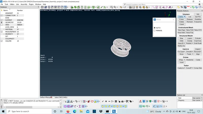
step 2:-
now check in list under volumes a PID will be assigned as PSOLID right click and select remesh as tetra rapid.
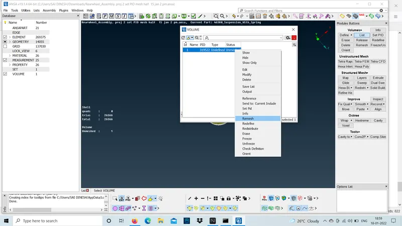
- we can use tetra rapid beacuse it's a huge components with lots of parts. so, ANSA may crash for some components so its better to diploy a tetra rapid and its totally based up on the industrial requirement.
step 3:-
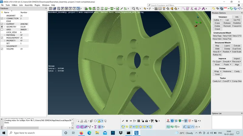
- we can cut those regions and check the mesh flow achieve inside the hollow areas.
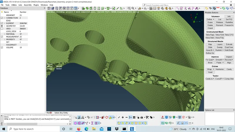
- connections should be diployed at bolt regions and check no parts should be floating on air .
step 1:-
use RB2 many nodes to join ball joint and wishbone should by using RB2 CLUSTER .
- select the slave nodes and middle click.
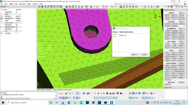
step 2:-
master node will be diployed in red colour at the centres of all the slave nodes and click finish to form a RB2 CLUSTER.
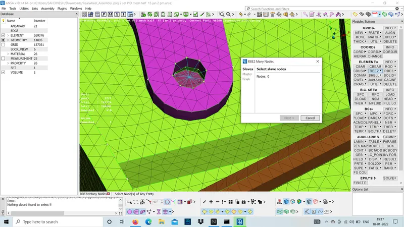
- RB2 cluster is formed for the ball joint and similarly forma cluster for the wishbone.
step 3:-
use RB2 many nodes and select the slave nodes .
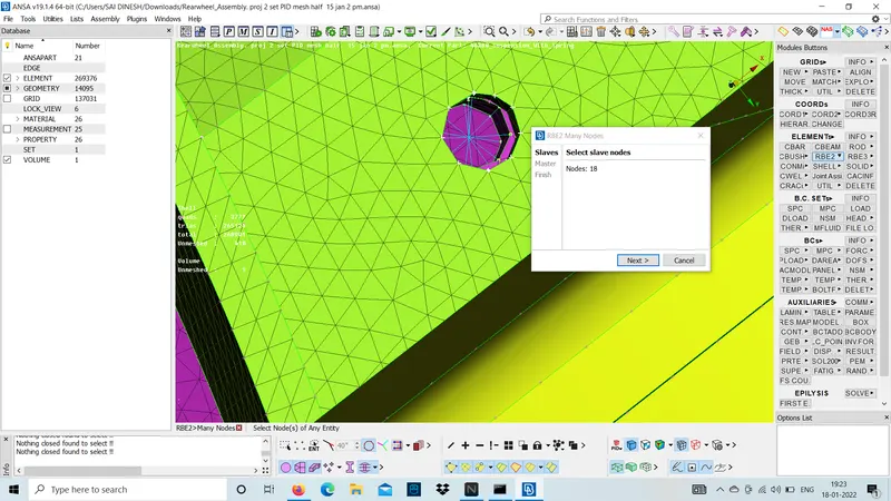
step 4:-
master node will be at the centre and click finsh.
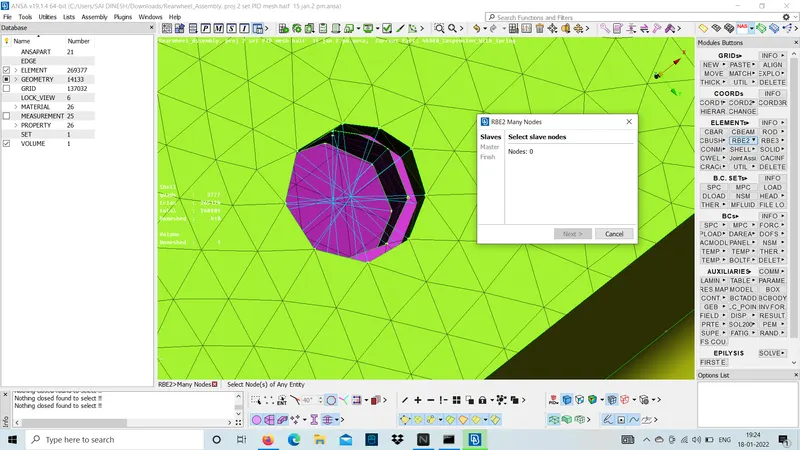
step 5:-
use RB2 two node and form a line between those two master nodes to diploy a bolt connection body as a two node RB2.
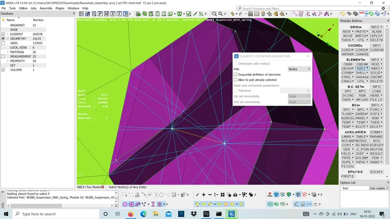
- similarly, do the same for the entire bolt regions to connect. every part should be attached by a connection.
now seam weld is diployed to join the coil spring lower insulator and pendulum bracket to join team using seam line.
step 1:-
use FE2curves under perimeters and change the FE to curve.
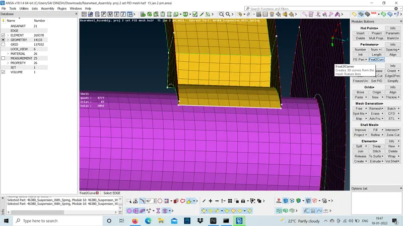
step 2:-
use convert and convert the curve into seam line.
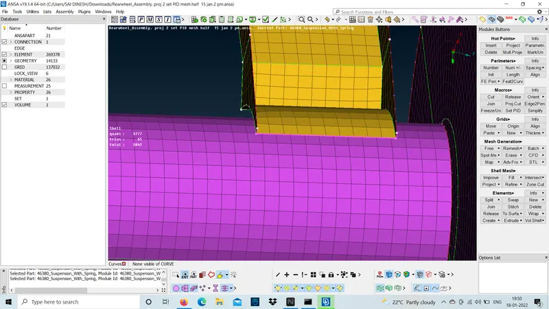
step 3:-
use connection and connect them by a seam weld using OVERLAP- SHELL and select P1 as base sheet and create a PID and give the search distance as 20.
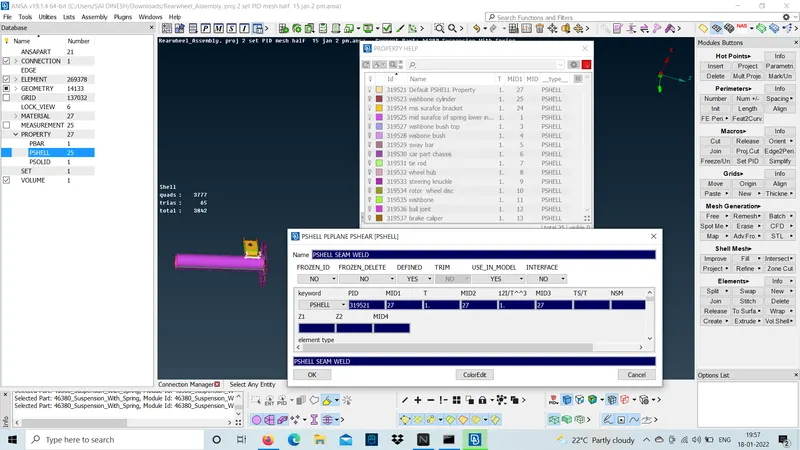
step 4:-
click apply and ok a seam weld is deployed with proper quality criteria.
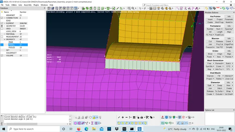
possible outcome:-
- How to diploy 3D mesh .
- How to diploy volume mesh.
- How to set PIDs based upon the PID region of selection.
- How to diploy bolt connection using RB2 many node and two node.
- How to diploy seam weld .
Result:-
The meshing and connectiion for the given suspension model is done.