Project - 2 - Meshing on the suspension Assembly
PROJECT-2
REARWHEEL ASSEMBLY
AIM: To create mid-surface and meshing for uniform thickness components and to generate volume mesh for non-uniform thickness components. To represent suspension spring as 1D element.
PROCEDURE: 1) Open rearwheel assembly model in ANSA. (Ctrl+ O)
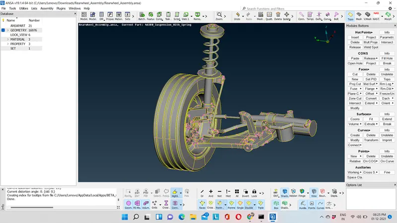
2) Check for the geometry. If there is any error try to auto fix or try tp resolve it manually.
UTILITIES→CHECK→GEOMETRY→EXECUTE.
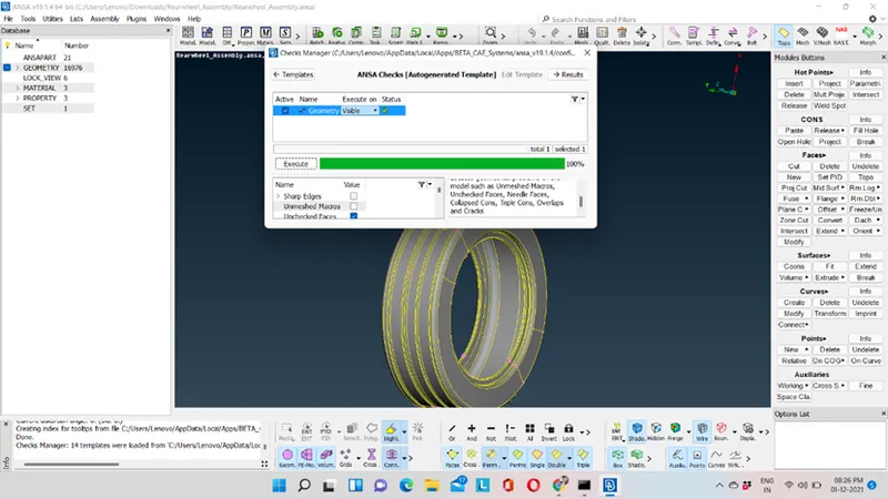
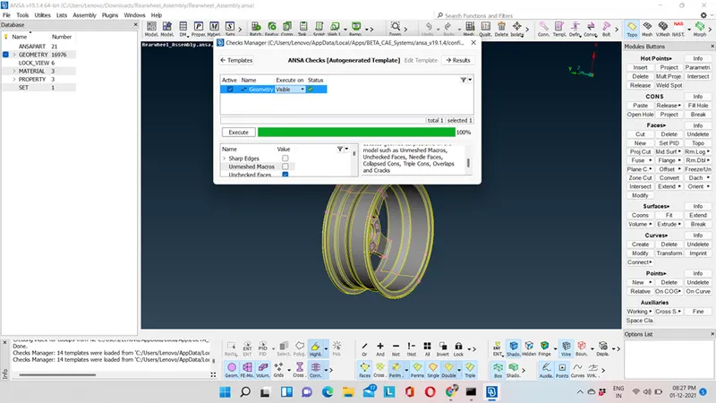
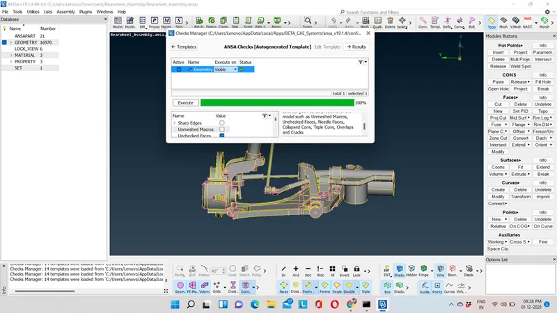
3) Give the perimeter length as 1.
MESH→PERIMETER/MACROS→SELECT THE ENTITY→ENTER THE VALUE AS 1.
4) Measure the thickness of different parts.
5) The part which is having non-uniform thickness (more than 5mm) we will mesh that part with tetra elements and the parts which has uniform thickness will be meshed with mixed elements.
6) Now, we will start modelling the tyre and rim part. Since thickness is more than 5mm we will model it as volume mesh. Remove unwanted cuts. Give the perimeter length as target length that is 6.5 for tyre and rim.
MESH→PERIMETER→LENGTH →MACROS/PERIMETER→ENETR THE VALUE →OK
7) Assign quality criteria. Press f11
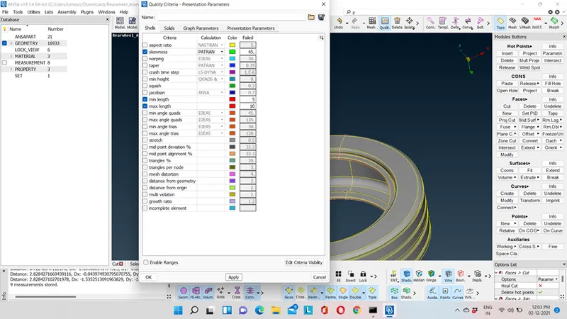
8) Enter the mesh parameters.
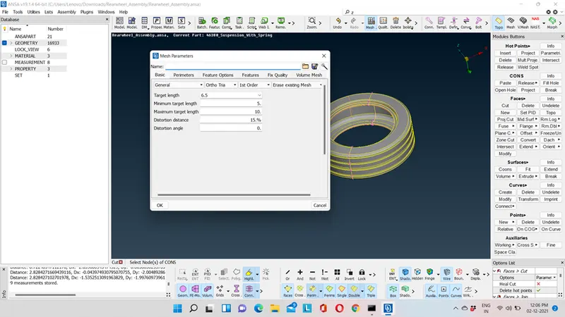
9) At the curvy areas mesh it with ortho tria and at the flat faces mesh it with tria elements.
MESH→SOPT MESH/BATCH→ORTHO TRIA/TRIA→SELECT FACE→OK.
10) If elements are failing to meet the quality criteria try to fix it using split, smooth and reconstruction options. Hence meshing for rim and tyre part is done.
11) Now we will generate mid-surface and meshing for the components with uniform thickness.
12) Create a mid-surface by using offset faces option with feature selection.
TOPO→FACES→OFFSET →FEATURE SELECTIONS→ENTER THE OFFSET DISTANCE→DELETE PARENT(YES/NO) →OK
13) Set the PID.
TOPO→SET PID →SELECT ENTITY→CONFIRM→NEW→SPECIFY THE PART NAME →ENTER THE THICKNESS VALUE→OK.
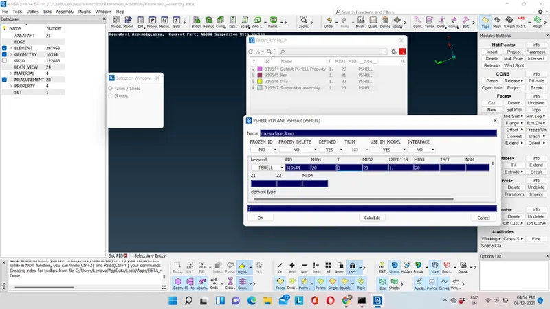
14) Give the perimeter length as target length and assign the quality criteria.
MESH→PERIMETER→LENGTH→SELECT THE ENTITY→ENTER THE VALUE →OK.
For assigning quality criteria press f11.
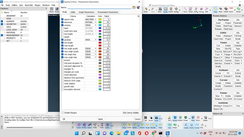
15) Enter mesh parameters.
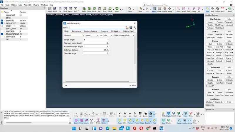
16) Now, mesh the parts with mixed elements using spot or batch mesh.
MESH→SPOT/BATCH→SELECT FACES→OK.
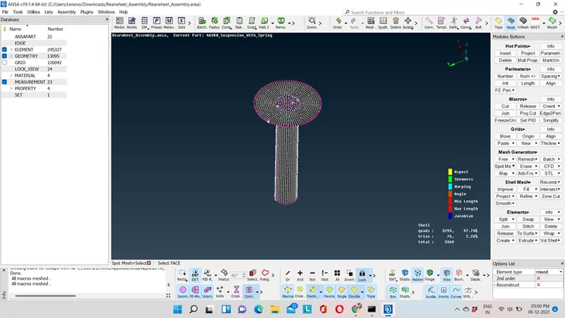
17) Now, to represent the suspension spring as 1D element follow the steps given below.
a) Measure the radius of spring.
b) Create middle curve.
TOPO→CURVES→MIDDLE→SELECT FIRST SET OF CONS→ CONFIRM→SELECT THE OTHER SET OF CONS→OK.
Use connect multi option to convert multiple curves into single curve.
c) Create COG.
TOPO→ON COG→CURVES→SELECT THE CURVE→CONFIRM.
d) Now, we will use C Bar element to represent the suspension spring as 1D element.
NASTRAN DECK→C BAR→ CURVE BOX→ENABLE THE ORIENTATION WITH NODE OPTION→SELECT THE CURVE→CONFIRM→SELECT COG AS ORIENTATION POINT→ENTER THE ELEMENT LENGTH AS TARGET LENGTH→CREATE A PID →ENTER THE RADIUS VALUE UNDER AREA SECTION→IT WILL AUTOMATICALLY CALCULATE THE AREA AND MOMENT OF INERTIA VALUE →OK
Now, to see the 1D bar element as solid element.
PRESS F11→PRESENTATION PARAMETER→ ENABLE LINE ELEMENT AS CROSS SELECT→ SELECT AS SOLID OPTION→APPLY →OK.
Hence suspension spring is represented as 1D element.
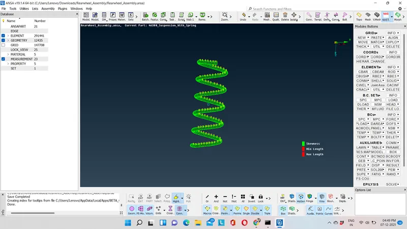
18) Now, we will mesh the component having varying thickness with tetra element.
19) Enter the quality criteria. Press f11.
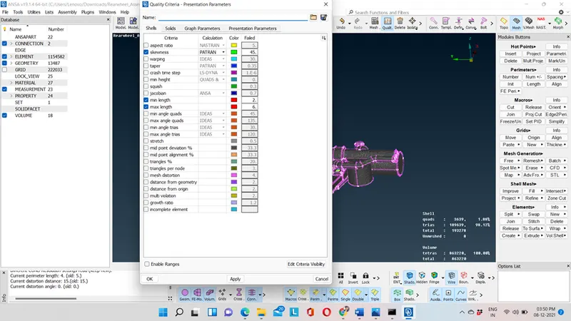
20) Assign mesh parameters.
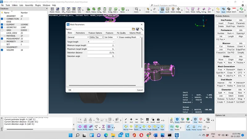
21) Now, remove the unwanted cuts and give the perimeter length as target length and mesh the parts with spot/batch mesh. Use ortho tria at curvy areas and tria at flat regions.
MESH→MESH GENERATION→SPOT/BATCH→OTHO TRIA/TRIA→OK
Hence mesh is generated for non-uniform components.
Now we will define volume to non-uniform component, tyre and rim and check for tet collapse. In order to define volume, the component should be a closed volume.
VOLUME MESH→VOLUMES→DEFINE→MANUAL→AUTO→SELECT THE ENTITY→OK.
We will use tetra rapid to do volume mesh for all the components with varying thickness. In the list if we will observe the status will be shown as unmeshed and unknown.
RIGHT CLICK→REMESH→TETRA RAPID→OK.
Now check whether the component is failing for tet collapse or not. Tet collapse value is 0.2.
Hence, volume mesh is generated.
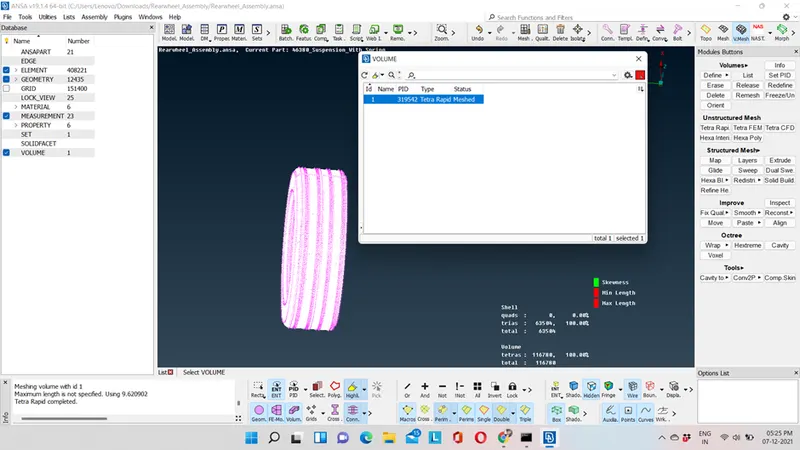
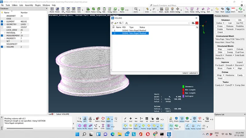
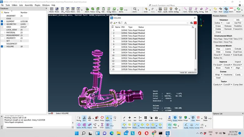
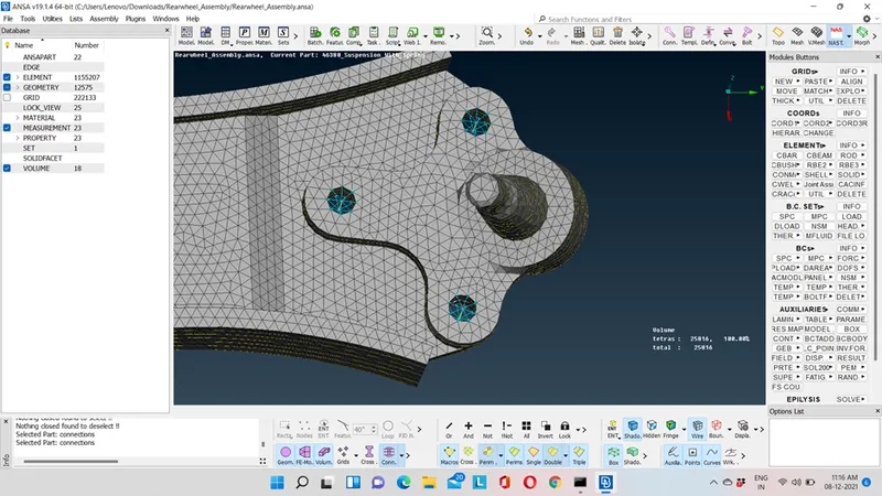
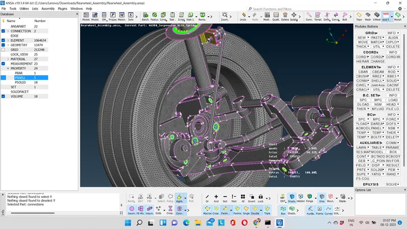
22) Now we will do connections. Wherever there is hole in between two parts we will joint those parts with bolt.
To represent a bolt connection, follow the procedure:
We represent bolt connection by using combination of many node RBE2 and two node RBE2 elements.
Constraint the perimeter nodes using many node RBE2 and join Two master nodes using two node RBE2 representing as stem.
Using many node RBE2:
NASTRAN DECK→ELEMENTS→RBE2 →MANY NODE→SELECT SLAVE NODES (NODES AT PERIMETER) → SELECT MASTER NODE→FINISH (WE CAN CREATE CONNECTION AS A SEPARATE PART) →CONFIRM.
Using Two node RBE2 to represent stem.
NASTRAN DECK→ELEMENTS→RBE2→TWO NODE→SELECT MASTER NODES→CONFIRM.
23) Now, we will do seam weld connections at bracket. To deploy seam weld connection, follow below steps:
a) Create a curve using feat2curve option.
MESH→PERIMETER→FEAT2CURVE→SELECT THE ELEMENTS→CONFIRM.
Now we will represent the curve as a seam line.
ASSEMBLY→CONVERT→CURVES→SEAM LINE.
CONNECTION MANAGER→SELECT SEAM LINE→CONFIRM→FE REPRESENTATION (OVERLAP SHELL) →SELECT BOTH THE PARTS → ENTER SEARCH DISTANCE, WIDTH, STEPS, WELD TYPE, WELD PID AND SELECT THE BASE→APPLY →REALIZE
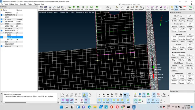
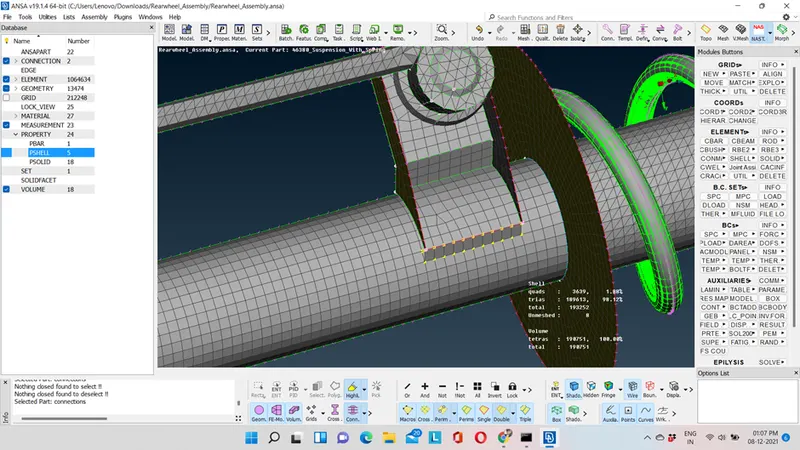
Hence, seam weld connection is generated.
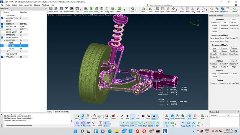
Enable the draw shell as solid option and save the model.
LEARNING OUTCOMES: 1) To generate solid meshing for non-unform thickness component.
2) To create mid-surface and meshing for uniform thickness components.
3) To represent suspension spring as 1D element.
4) To deploy connections.
CONCLUSION: Hence, we can conclude that the component having thickness more than 5mm should be modelled as solid mesh and component with uniform thickness should be modelled with mixed elements and the suspension spring or torsion spring should be represented as 1D element.
To download the model please click on the link given below:
https://drive.google.com/file/d/1yIMJ4mioFBtcFcUix3JuEAfcyJknpmd3/view?usp=sharing