Project - 2 - Meshing on the suspension Assembly
Aim:
Mesh the given rear suspension accordingly with 2D & Volume meshing as per the given quality criteria. Connections to be deployed for the model. Replicate the model symmetrically after all the meshing and connections.
Procedure:-
• Geometry Clean-up.
• Mid surface extraction & 2D meshing.
• Volume Meshing.
• Bolt & Seam Weld Connection.
• Symmetrical Replication.
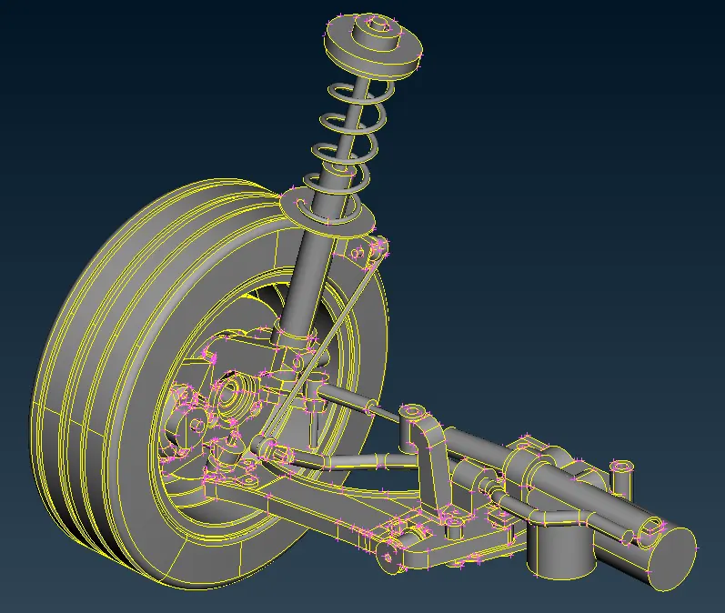
Step 1:Import the CAD geomentry of suspension assembly in ANSA.
Step 2: Now check the errors and assigning property id (pid) for each component.
If there are any error, you can be fix automatically. In this model some error are fixed by identifying the error and clear that error by untoggle the line and stitch the surface again or delete the unwanted surface present in that model manually they are shown as below.
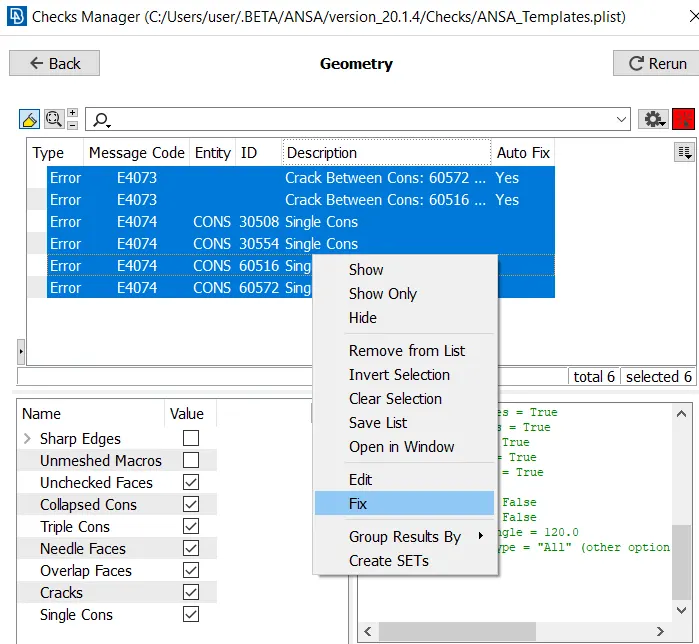
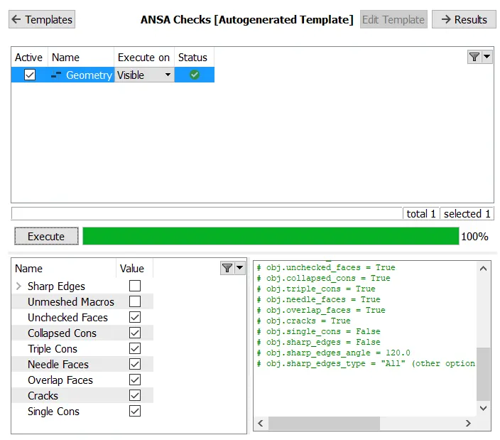
After clearing all the error, rerun the geomentry check to make sure that there is no other error.
Step 3: Now after clearing all the geomentry check mesh the components individually. If the component has uniform thickness then go with 2d meshing and if the part does not have uniform thickness or thickness greater than 5mm go with volume mesh.
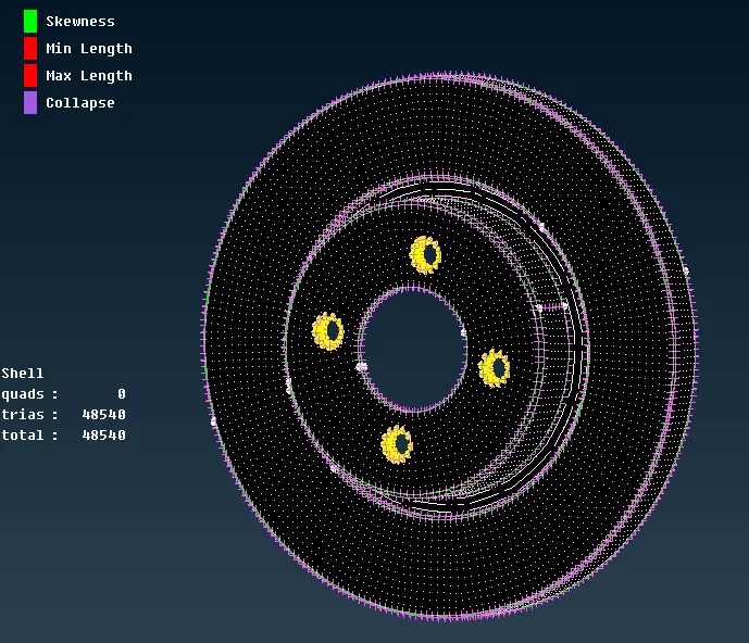
first mesh the tire and rim component.
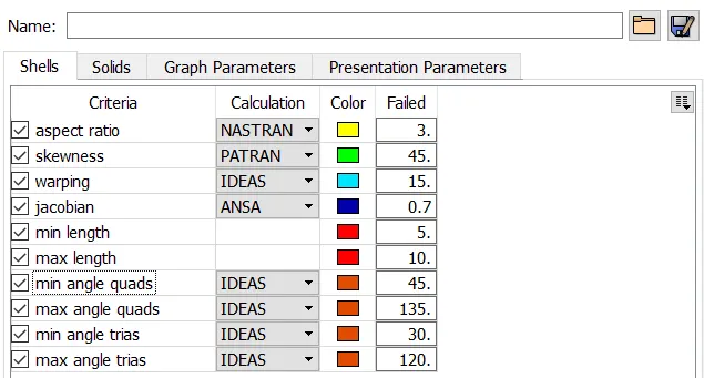
Give the mesh parameters and quality parameters.
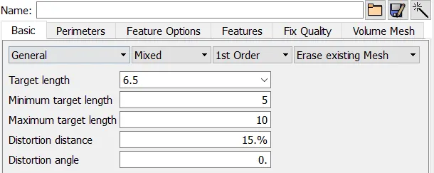
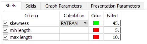
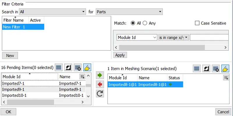
Now you ca create a batch mesh scenario for both the components and do the meshing. After meshing you can improve the quality of the components.
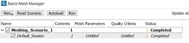
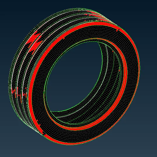
The elements that are red are failing for maximum element and now you have to manually rework on the failed elements.
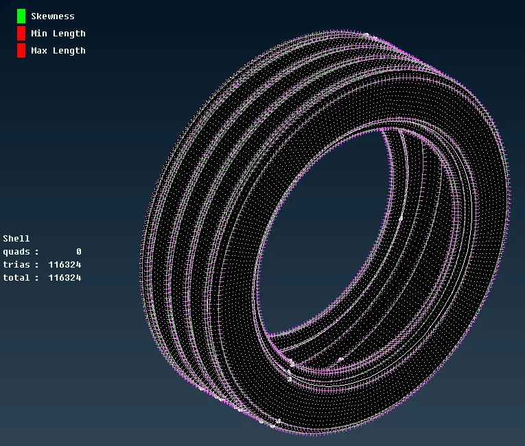
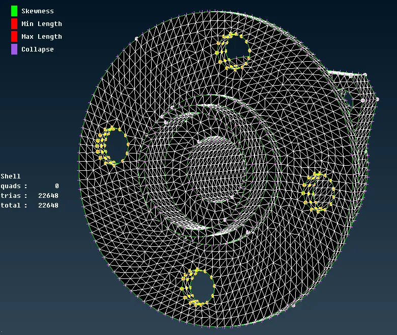
After creating the components now create a volume for the component using define option under volume tab.
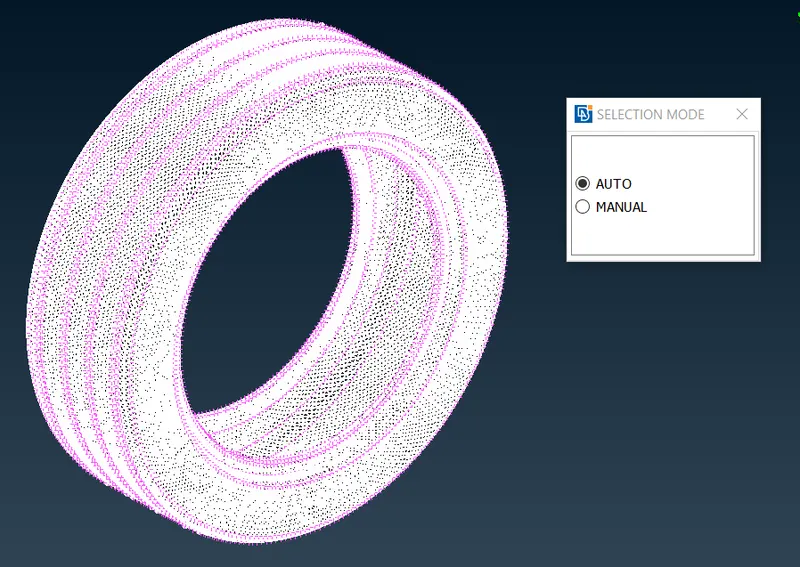
after creating the volume, now use tetra mesh option under unstructured mesh tab to create a tetra mesh for the component.
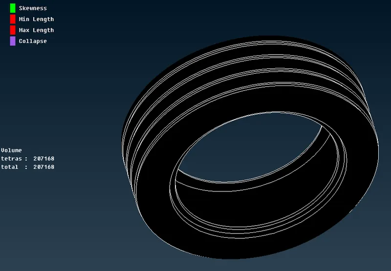
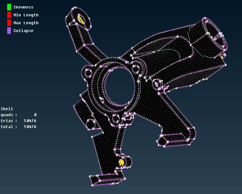
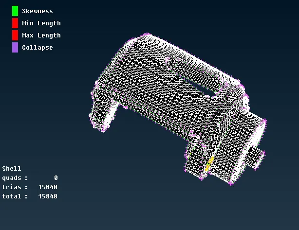
Do the same procedure for the rest of the components like rim,disc,hub,knuckle and caliper.
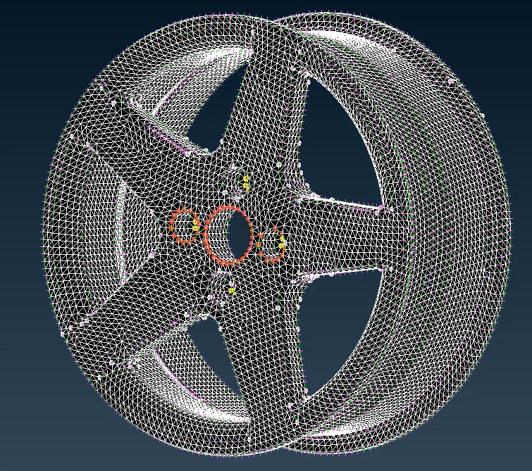
step 4: Now for components with uniform thickness generate the midsurface and mesh the components.Once the geometry is clean, extract mid surface by Faces->Mid Surface->Skin method for parts which are having uniform thickness and Faces->Middle for non uniform thickness parts.Complete the meshing of 2D elements by Mesh Generation->Best in Mesh module.
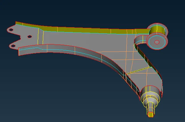
Now give the quality parameters and mesh the component.
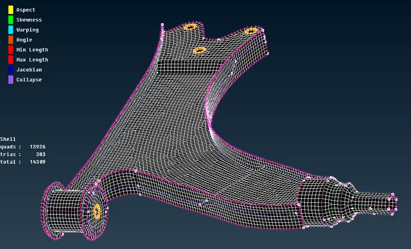
Do the same for other similar components.
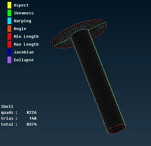
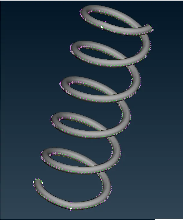
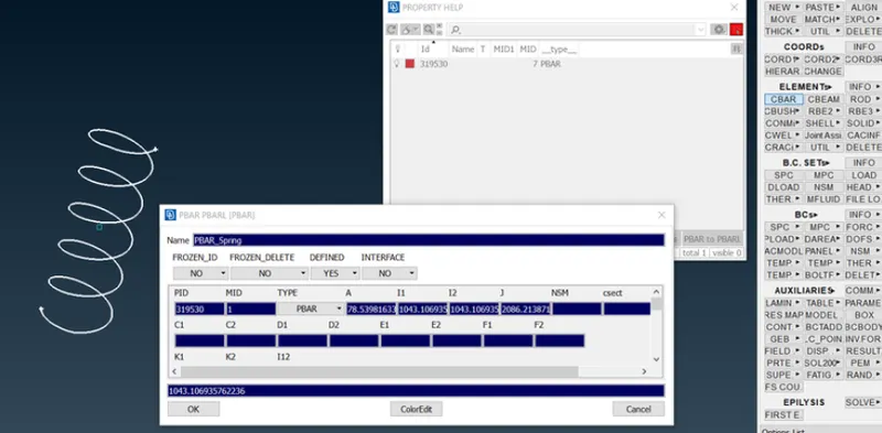
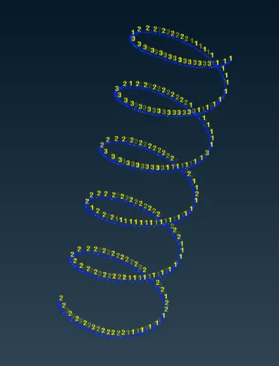
After meshing the compoents you need to mesh the spring which can be done by cbar elements.
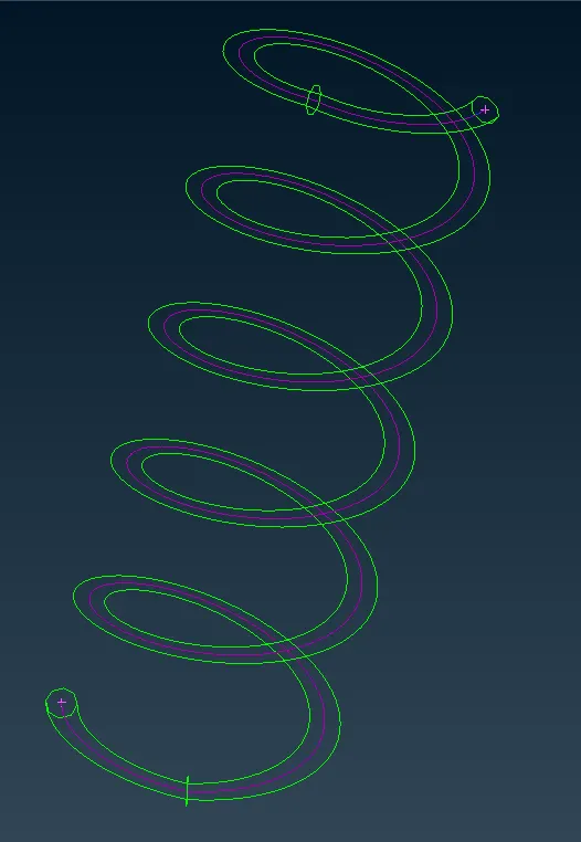
1D meshing is to be performed in Spring. Generate middle curve running through the entire spring using Curves->Middle in Topo Module as
shown in Fig 5.2. Convert the curves to a single curve using Curves->Connect->Multi in Topo Module
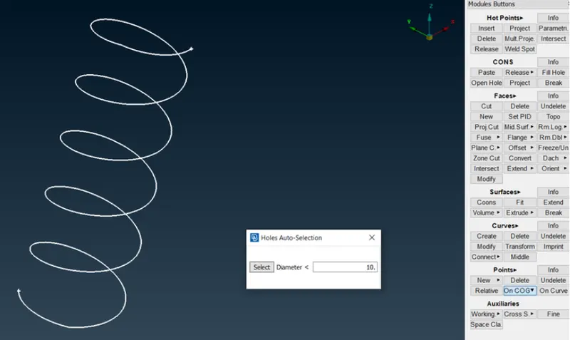
Define (Center of Gravity) COG point using Points->On COG in Topo Module
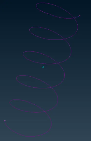
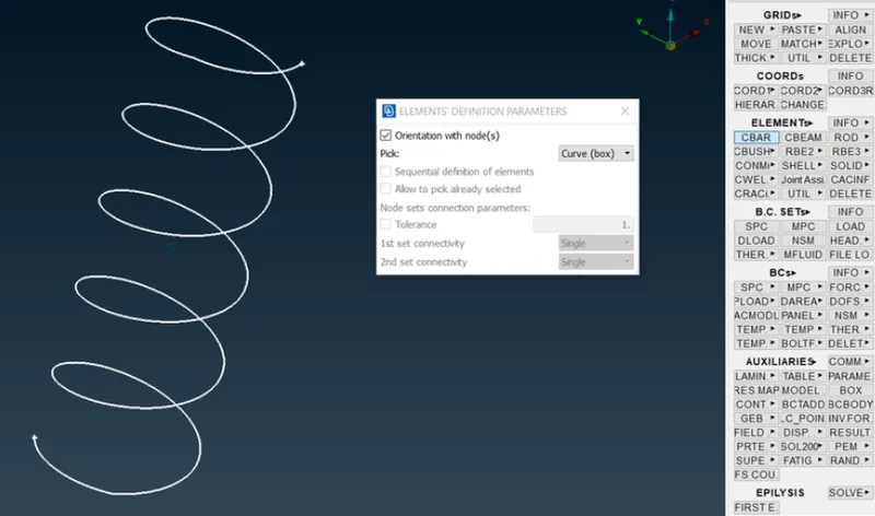
Open NASTRAN deck to assign 1D mesh element. Select Elements->CBAR, check "Orientation with nodes" and pick "Curve (box)", select the
spring curve and click on middle mouse click.
step 4: Once all the components are meshed, deploy connections accordingly.
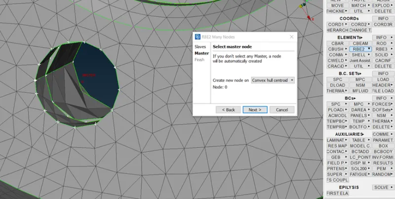
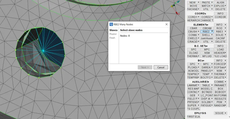
Use RBE2 in NASTRAN deck. Create RBE2 component for each hole separately by Elements->RBE2->Many Nodes
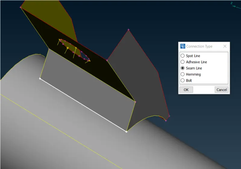
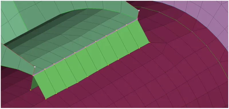
Deploy Seam weld connection for the tie rod bracket and the strut.Select Curves->Cons2Curve in topo deck and create a curve along the weld surface. Convert the curve to seam line.By using connection manager, select the two components to be welded and consider it as P1 & P2, P2 should be the base sheet on which the weld should be deployed. Select FE rep type as OVERLAP-SHELL, Search distance = 10 mm, Base sheet = P2, Step length = 4 mm, Width = 4 mm & Root Shells = Double Row.
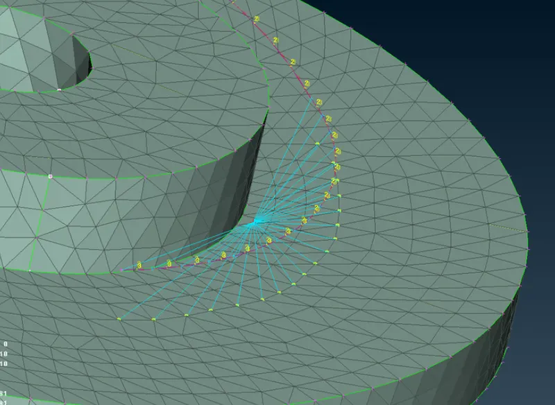
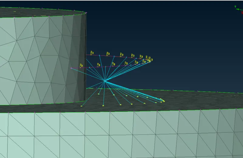
The spring element should be connected to the neighbouring elements using Cluster RBE2. Select Elements->RBE2->Many Nodes in
NASTRAN Deck to connect the spring and the neighbour part with single master node.
step 5: Once the complete meshing and deploying connections, the model it to be symmetrically replicated. the steps for replication is as follows;
• Go to the Transform option in the toolbar, select "Copy".
• Select all the elements that are to be replicated
• Select the "Mirror 3 points plane" underuse option.
• Select the points and apply and Finish.
Result:-
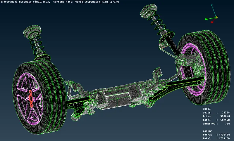
The given Suspension assembly is meshed using 2D and tetra mesh with the prescribed quality criteria. Connections are deployed as required.
The other half of the assembly is reflected symmetrically.