Project-2-Meshing of Door Inner Panel Challenge
Aim: Meshing of Door Inner Panel Challenge as per provided Quality
Criteria.
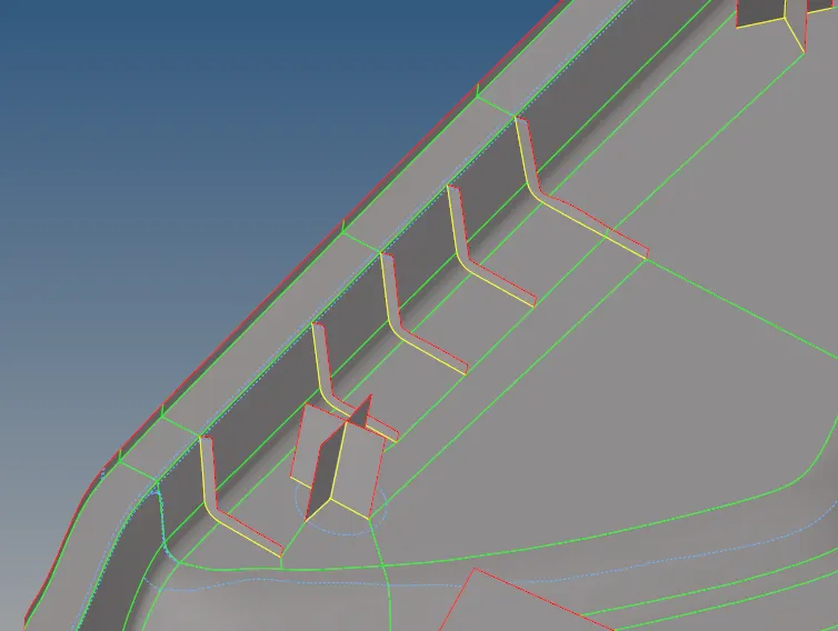
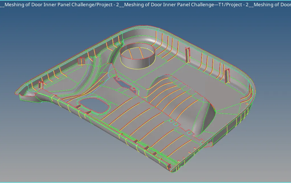
Given model:
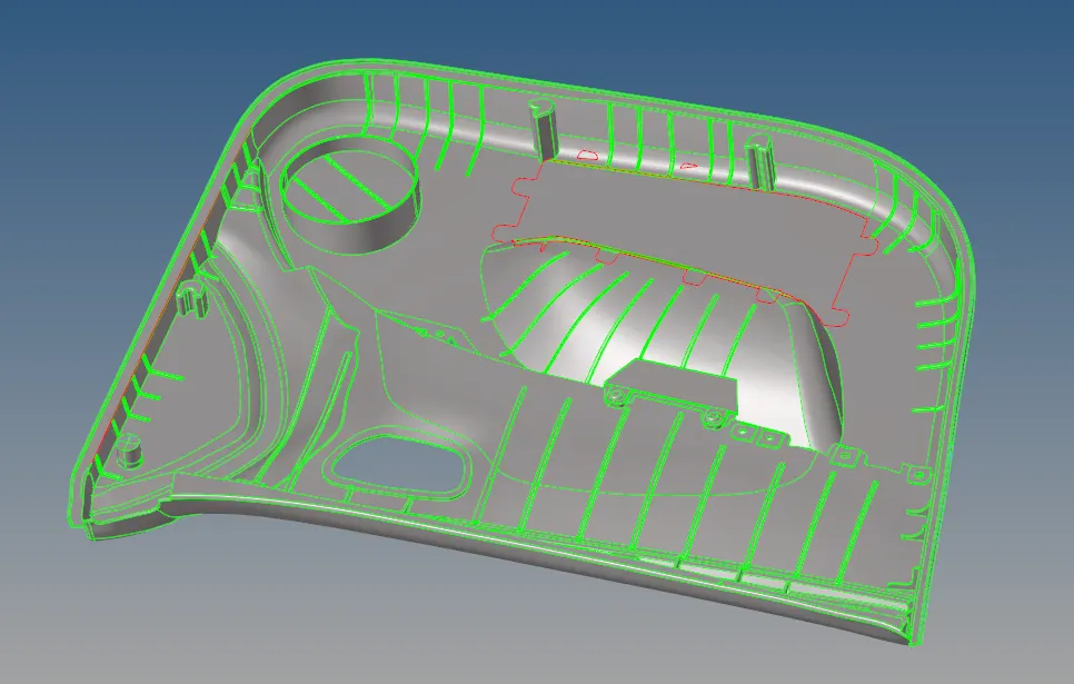
Objective:
1. Geometrically clean the model and making sure no deformities of surface are present.
2. Extracting the mid-surface of the model and clean it to avoid any errors.
3. Generating mesh on mid-surface using mixed element criteria.
4. Carry out the quality check of the generated elements.
5. Provide thickness to mesh as per part.
Procedure:
1. First of all geometric clean the model after we import it, since there might be some distortion or error in the model. As provided in the question defeature all the pin-holes and small surface fillets that fail minimum length criteria.
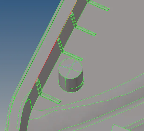
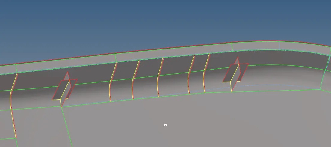
2. Next step is to extract mid-surface of the component. But first we need to check for the uniform thickness of the model to decide weather to proceed with sheet metal model method or plastic model method. As the thickness is not uniform, we can extract mid-surface using off-set+sweeps+planes method. Now check for any deformation in mid-surface and do through geometric cleanup of the mid surface.
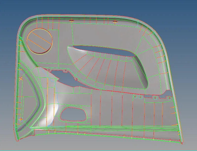
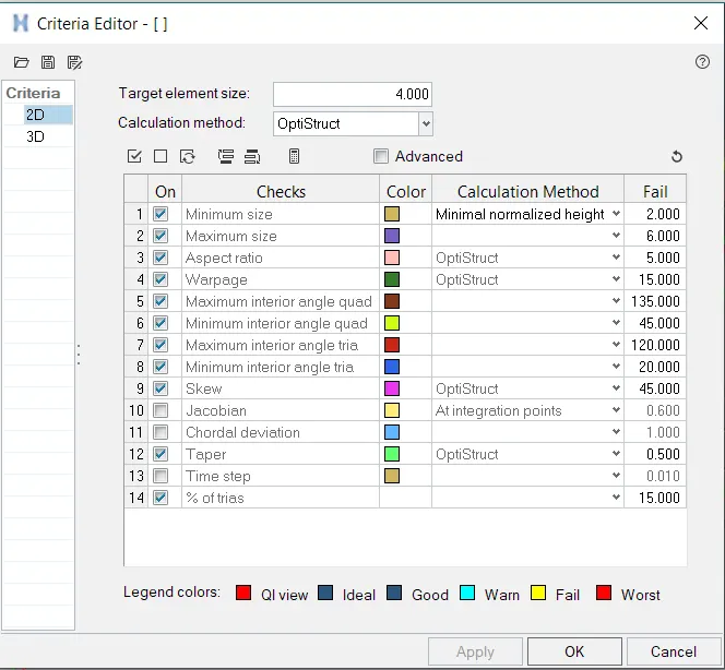
3. Now set the quality criteria for the meshing process as provided in the question, using Criteria file setting in Preference Tab.
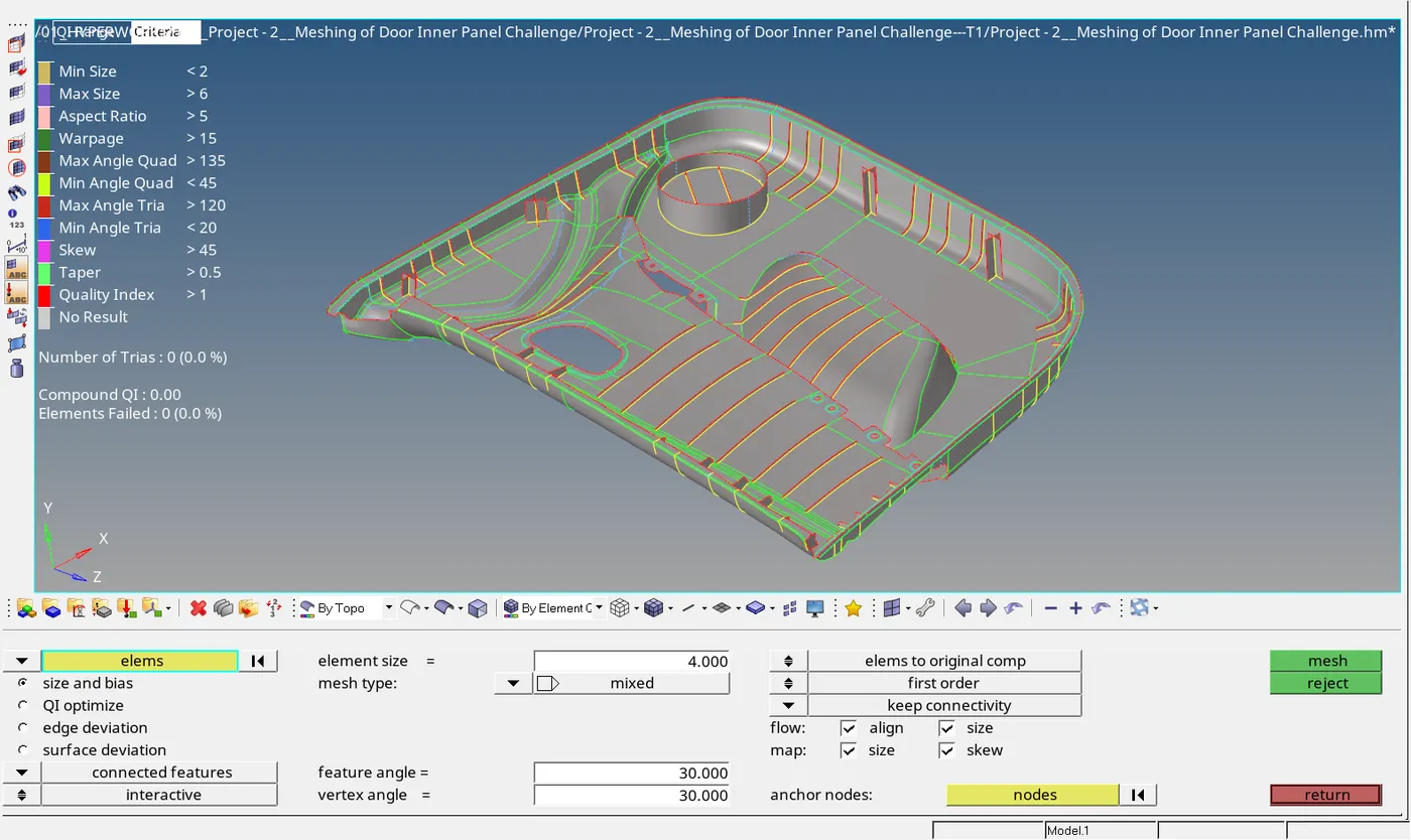
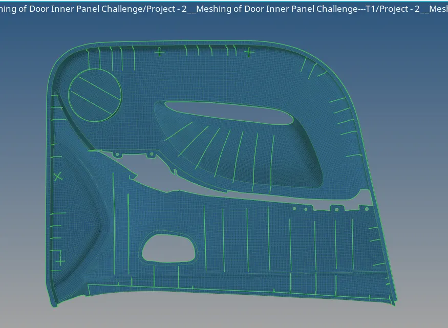
4. Now mesh the mid-surface using Auto-mesh command in 2D tab. In this change the element type mixed and element size to 5 mm, also ticked the Align & Size option for better mesh flow. For a better mesh flow try to mesh the mid-surface step by step instead of in one go. After meshing the component should look somewhat like this:
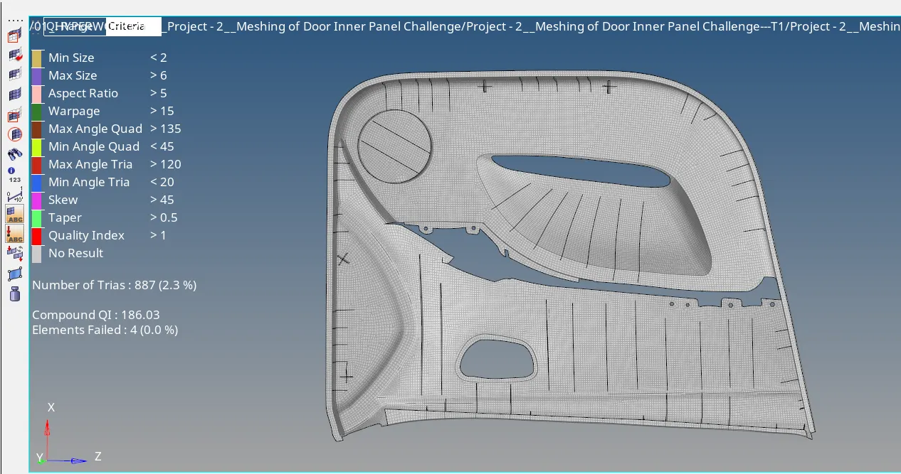
5. Next is to check for fail elements as per Quality criteria using Quality check command in 2D tab as shown below:
And also by turning on Elemental Quality View as shown below:
6. After meshing we need to check for the connectivity of the mesh element by using Equivalence command.
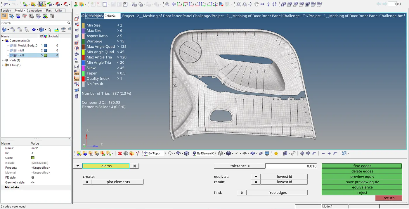
7. It is cleared that the component has cleared all the quality criteria expect for minimum element size. Since the provided component it self has small surface so we will leave the minimum elemental size criteria as it is because on correction the shape of the geometry will change itself.
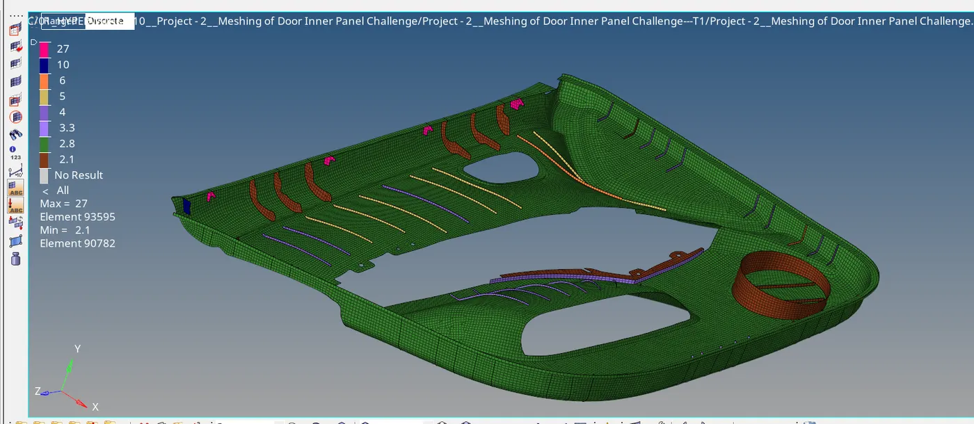
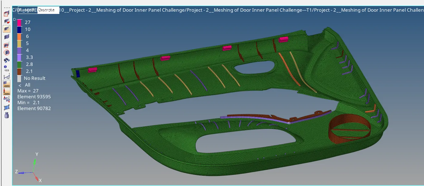
8. As it is a plastic component, we need to bifurcate the component as per the thickness of the various areas of the component. A list of different thickness & their respective property is created as shown below:
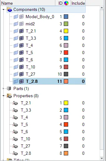
9. Transferring the different surface of the component as per their thickness.
10. The final mesh of the Plastic component is shown below as pe required thickness:
Conclusion: This project helped me to understand how to mesh a plastic component with proper Geometric cleanup & Quality clearing along with proper mesh flow.
[ NOTE: Since the size of the file was > 20 Mb, I have attached Notepad file with google drive link of the model in it. ]