Project-2-Meshing of Door Inner Panel Challenge
OBJECTIVE
The objective of this project is to generate a mesh with a target element size of 4 for the given inner door panel with the following quality criteria mentioned below.
Quality criteria
| Sl no | Quality criteria | Value |
| 1 | Aspect ratio | 5 |
| 2 | Skewness | 45 |
| 3 | Warping | 15 |
| 4 | Taper | 0.5 |
| 5 | Min length | 2 |
| 6 | Max length | 6 |
| 7 | Min angle quad | 45 |
| 8 | Max angle quad | 135 |
| 9 | Min angle tria | 20 |
| 10 | Max angle tria | 120 |
| 11 | Tria % | 10 |
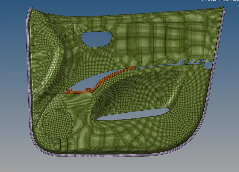
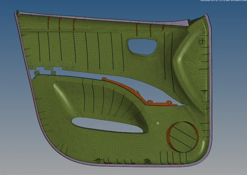
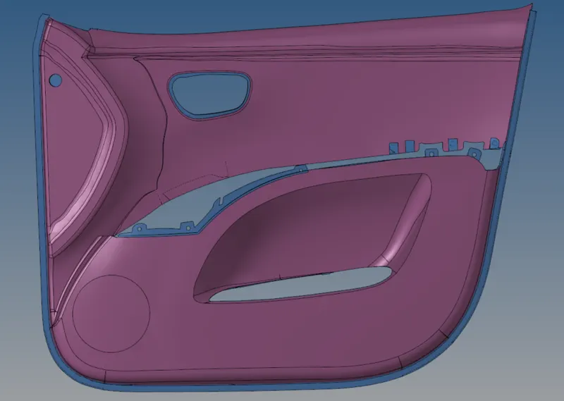
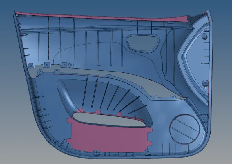
The images of the inner door panel is given below.
PROCEDURE
The model is first imported to hypermesh. Since the model is very complex with varying thickness and also contains a lot of ribs automidsurface option fails here. So manual midsurfacing has to be done here. Since the thickness of the component varies, the thickness at various points is found out by creating a temporary node on one surface and then projecting it on the surface normal to it and then the distance is measured by the 'distance tool'.
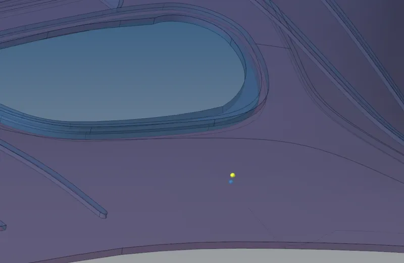
Figure shows the methord for thickness measurement.
The midsurface is generated manually by 'offset' option present in surface edit tool. Some of the ribs present have varying thickness , in such cases the rib is generated by first creating a midline on the top surface of the rib and then projecting it to the base midsuface. Then the rib surface is generated by using 'ruled' option present in the 'surfaces' tool. The generated midsurface of rib is attached to the base midsurface by utilizing the 'extend' option present in 'surface edit' tool. Some of the ribs is easily generated by firstly defeaturing the rib of fillets using the 'defeature' tool and then generating the rib using 'surface pair ' option present in the 'final edit tools' in midsurface tool.
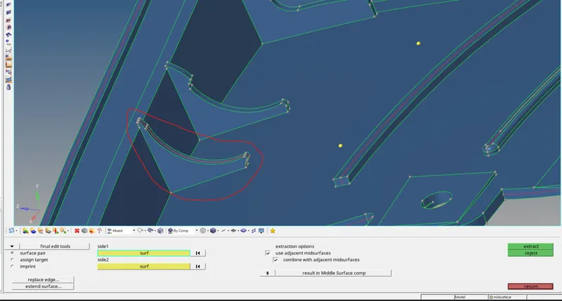
Rib generated using surface pair option
Areas that have a thickness greater than 6mm is captured as shown below.
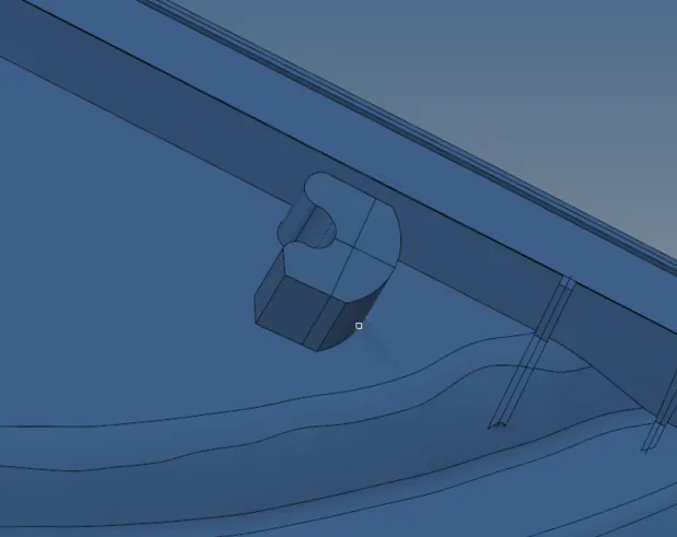
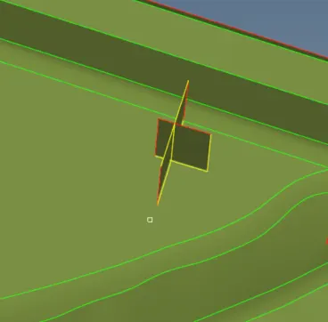
Area having more than 6mm thickness is captured as shown above.
After creating the midsurface, it is then meshed using 'automesh' tool. Rebuild tool was extensively used to create better meshes.
Some of the main rules followed for otaining a good quality mesh were:
- Cyclical quads were avoided as much as possible
- Back to back tria were avoided
- Opposite tria elements was avoided as much as possible.
- Tria elements on the edge of the geometry was avoided
- Tria elements were avoided near the holes.
- Tria elements on the feature lines and fillets were avoided as much as possible.
- Tria concentration was made less
The main tools that were used to correct the meshes were 'replace','edit elements' ,'translate','project','align', and various tools present in 'quality index' panel such as swap edge, element optimize, smooth etc..
'Extend ' option present in 'mesh edit' tool was also utilized to connect elements of some ribs with the elements of the base midsurface .Finally after meshing all the components we check it for any equivalence issues using edges tool. Extra free edges if present are checked using the 'find edges' option in 'edges' tool. For finding if any duplicate elements are present in the final mesh we use duplicate option in the 'check elements' tool. 'Normals' tool is used for checking and correcting the direction of normals of elements , if any. Finally the appropriate thickness is assigned to the mesh manually.
RESULTS
The midsurface of the component was captured manually and the mesh was created satisfying all the quality criterias.
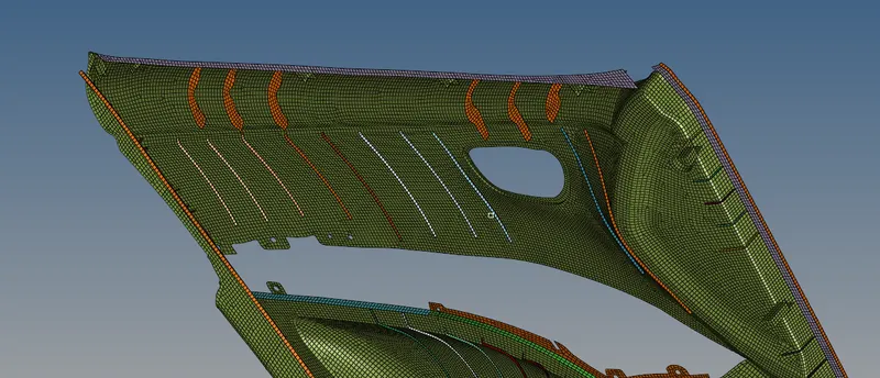
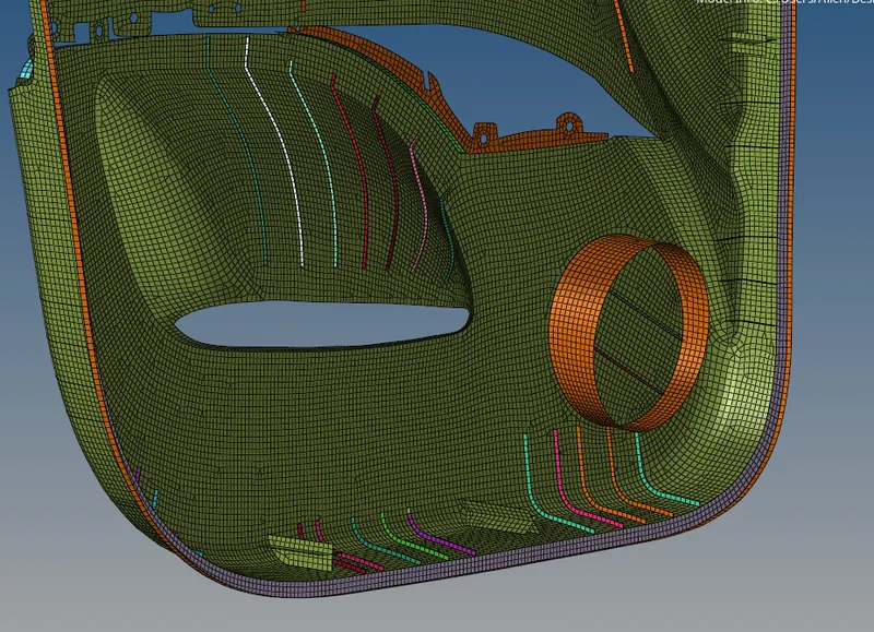
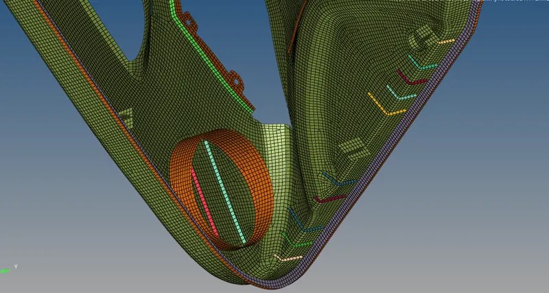
The final meshed image of the model is shown below.