Project-2-Meshing of Door Inner Panel Challenge
AIM: - To mesh the given door trim panel along with all its feature like ribs, dog-house etc. using Hyper mesh.
OBJECTIVE:
- To Extract the mid surface.
- To Capture the features and dog-house properly.
- To Mesh the mid surface with the given element Quality criteria and maintaining proper mesh flow.
Given Quality Criteria:
Target Element Length = 5 Units
|
S. N |
Quality Criteria |
Value |
|
1. |
Aspect Ratio |
5 |
|
2. |
Skewness |
45 |
|
3. |
Warping |
15 |
|
4. |
Taper |
0.5 |
|
5. |
Min. Length |
2 Units |
|
6. |
Max. Length |
8 Units |
|
7. |
Min angle Quad |
45 |
|
8. |
Max angle Quad |
135 |
|
9. |
Min angle Tria |
20 |
|
10. |
Max angle Tria |
120 |
|
11. |
Tria % |
10 |
THEORY: -
It is act as an interface between the interior of the car and the inner workings of the door, and between vehicle occupants and the door. It is expected to meet a variety of design specifications regarding safety, aesthetics, and functionality. In addition, they are expected to continue the material theme of the dashboard and pillars while concealing intricate electrical and mechanical components for operating locks, windows, and other features. The door panel has evolved from a simple two-part system of the latch and simple winding mechanism to a more sophisticated enclosure. Doors currently have an inner full-width panel consisting of electronic windows, a central locking system, and speakers. These panels typically consist of a foamed core covered with either textiles or plastics.
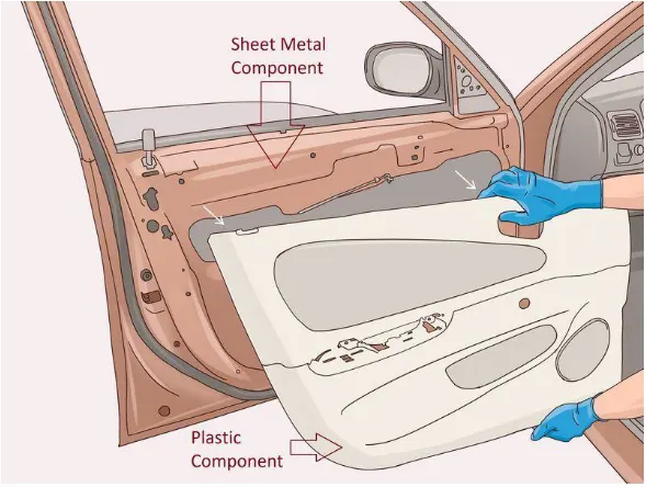
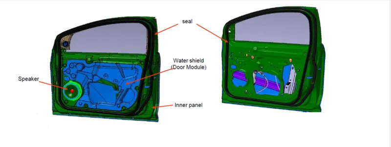
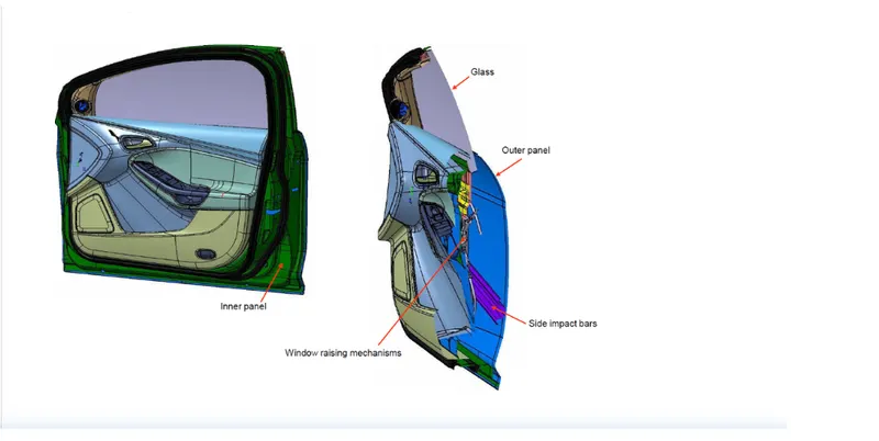
Generally, materials used for the door panel are acrylonitrile-butadiene-styrene (ABS), Polypropylene (PP), ABS/polycarbonate alloys.
Key Properties of ABS
- High rigidity.
- Good impact resistance, even at low temperatures.
- Good insulating properties.
- Good weldability.
- Good abrasion and strain resistance.
- High dimensional stability (Mechanically strong and stable over time)
- High surface brightness and excellent surface aspect.
PROCEDURE/STEPS: -
- import cad geometry file
Here we have Plastic Model “Door Inner Panel”. In this Model we have many ribs with surface fillets it means we need to work Manually.so, we start our work by Importing the CAD geometry in Hyper Mesh GUI.
Command: File >> Import >> Model >> Locate the file directory (as per given figure) >> hit Open >> hit Import.
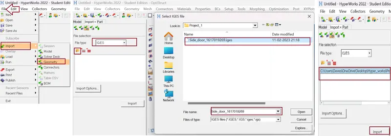
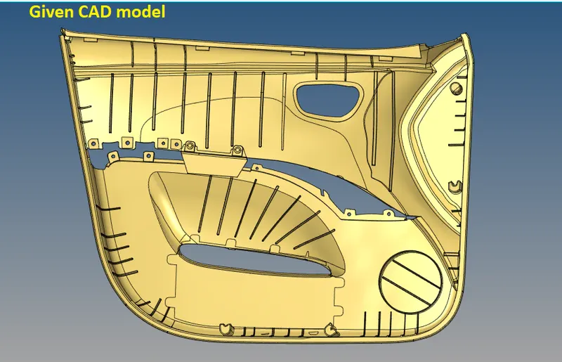
From the imported CAD file, we can clearly observe there are so many features and Locators. Also, we can see this component has different thickness on each feature.
- Checking for solid surfaces
Some times when model is import in hyper mesh then model is shown in "wireframe mode" we have to change the view to shaded by selecting "shaded geometry" view. And we check the model for any solid surface is present of the component, because we are working for the 2D mesh modelling for that we need to avoid the 3D solid surfaces.
for deleting the solid surface we have to select the delete tool and change the option to "solid" in which it only select the solid surface if available and delete.
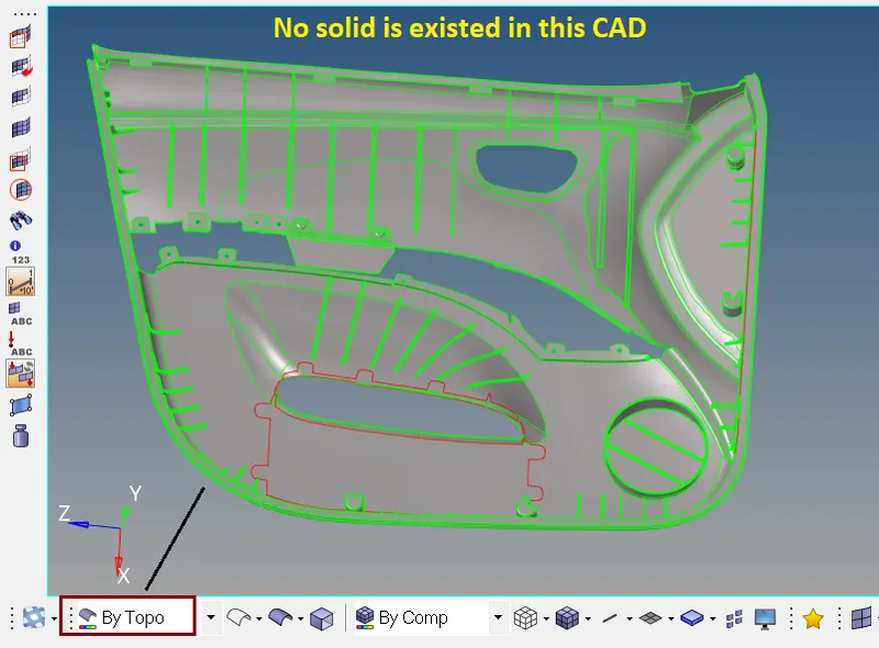
- Detach the unnecessary surface
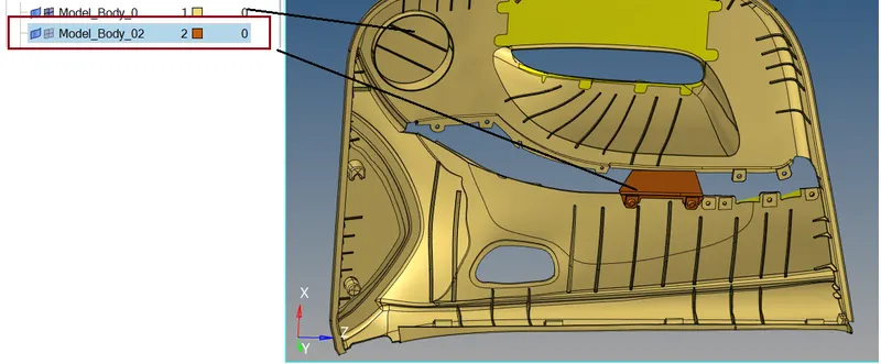
Here we make a different collector and move the unnecessary surface.
Command: Tool >> organize >> Collectors >> select the surface >> check the dest Component >> move

- CAD Geometry clean up
In this step the given model undergoes geometry check. Where all the defects such as collapsed faces, cracks, free edges, T-edges are clear.
Now switch “ON” the wire frame mode and check surface by surface.
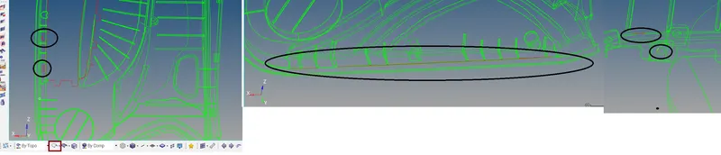
Tools used in Geometry clean-up/topology clean-up
Tools>Edge Edit Panel

Toggle (edge pair at a time) Select an edge; equivalences with other free edges found within a user specified tolerance.
Replace (1 edge pair at a time) Select 2 edges to equivalence together. Control which edge to retain and which to move.
All the box selected tools are used here for geometry clean-up
For create missing surfaces
Geom >> Surfaces >> Ruled or Geom >> Quick edit >> filler surface or 2d >> spline >> surfaces only.
- Mid-surface extraction:
Before going to the Mid surface extraction check for thickness of entities. By using Command: Geom >> distance. We found different thickness on each feature. For the parent surface the thickness is 2.8 units. To simply extraction of mid surface. Very first we extract the parent surface and after then we extract another feature.
- Mid surface for Parent surface-
select offset tool
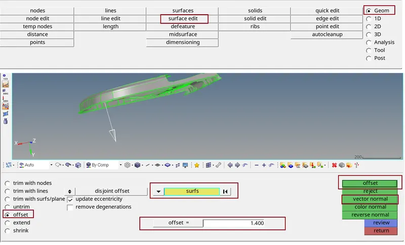
steps:
a.) Offset moves the selected surfaces without retaining their connections to surrounding geometry.
b.) select the surface and make a duplicate of same surface
c.) input the value which is half of the thickness
d.) to check the direction, click on vector normal so that we can see the offset direction, also one can change the direction by reverse normal.
e.) at last hit offset.
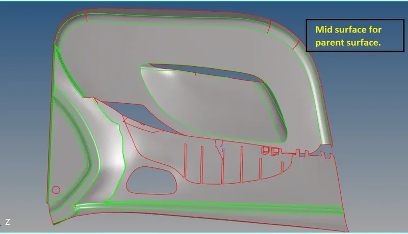
- Mid surface for Ribs:
For ribs mid surface we follow:
Steps
a.) Create a mid-line with the help of ribs edges.
b.) Trim the base surface with the help if this free line
c.) Make a surface with the help of these two lines.
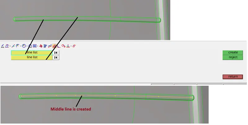
Now we go Geom >> surface edit
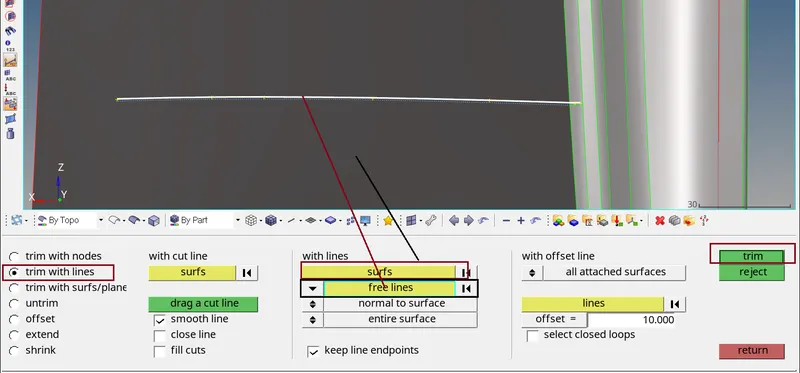
Now I am able to make a surface with the help of these two lines. For creating surface we use Command : Geom >> Surface >> Ruled >> select the lines >> hit create.
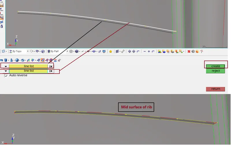
Similarly, we can extract mid surface for all the ribs
- Mid surface for Dog-House and Projector
Similar steps we follow for extracting mid surface for dog house.
a.) Create a mid-line with the help of Points or temp nodes.
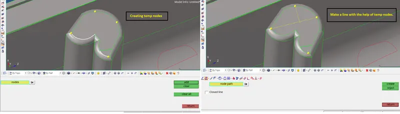
b.) Trim the base surface with the help if this free line
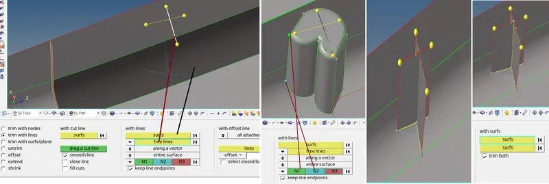
c.) Make a surface with the help of these two lines.
d.) Trim both the surface.
- Mid surface for another feature
Here we have some surface projector we need to extract mid surface for these surfaces.
For this we use command: Geom >> mid surface >> final edit tools >> select surface pair >> select side 1 and side 2 >> hit extract.
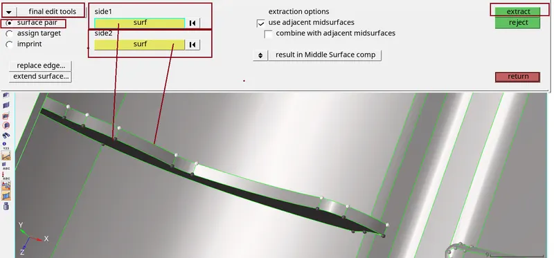
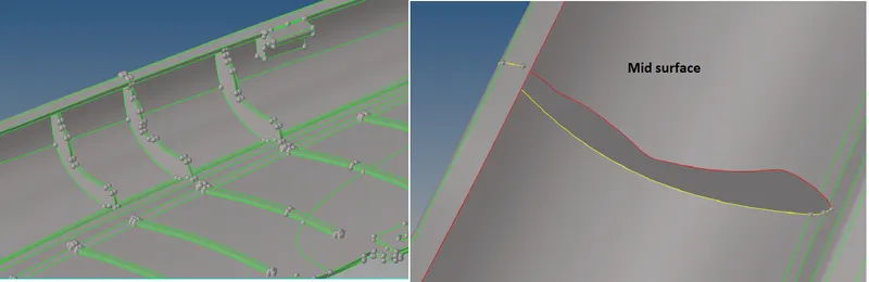
After getting mid surface we need to extend this mid surface to base surface. For this we use command : Geom >> surface edit >> extend.

Final mid surface:
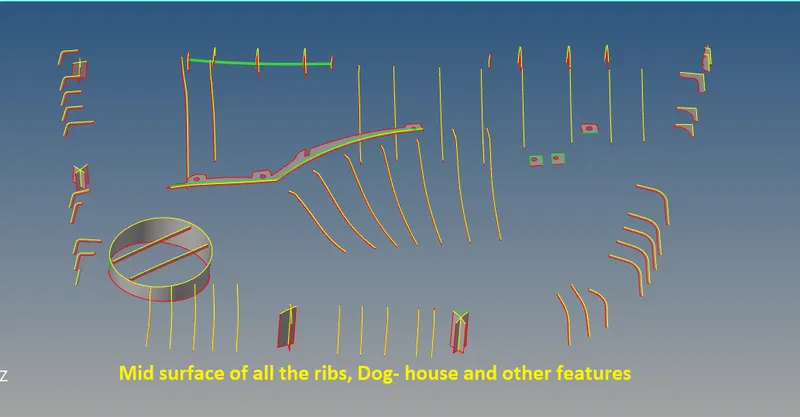
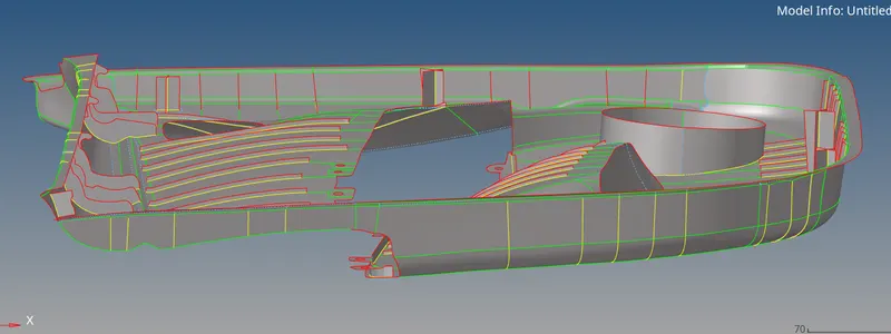
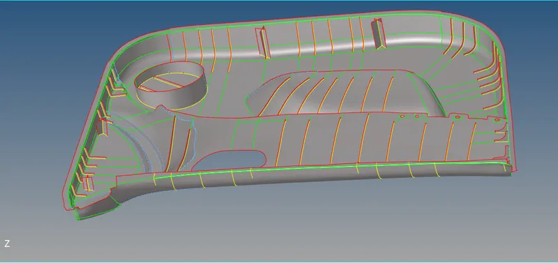
- Geometry clean-up:
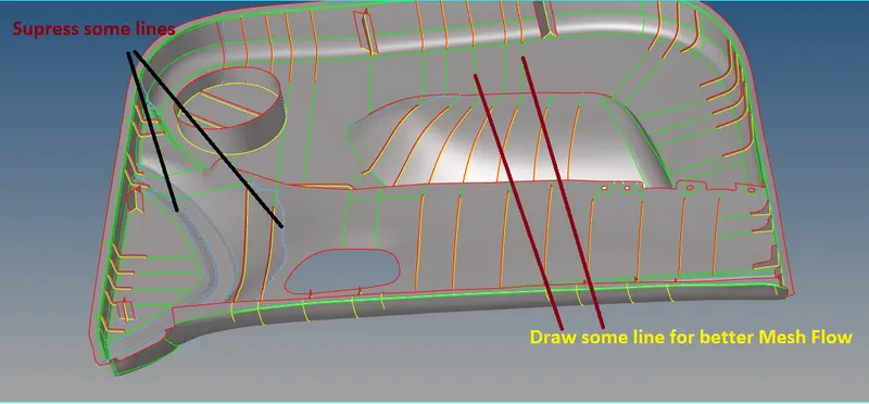
Before Meshing we need to clean our mid surface, for Geometry clean-up we follow some steps
- very first we change the geometry colour Mode Auto ---->>> Topo for better visibility.
- To clean the Geometry of the Components manually we use the “Quick edit panel” by pressing F11 and using some of the tool shown below.
- Quality Criteria setting:
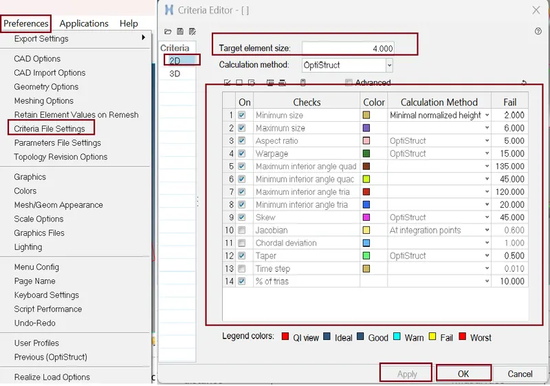
Now our next objective is to do Meshing on the Component. Before meshing we need to set quality criteria.
Command for setting Quality Criteria: Preference >> Criteria file setting >> Edit the card as per figure below >> hit Apply >> ok.
- 2D Meshing:
Now the time to start meshing for this we use....
Command: 2D >> automesh >> edit the tab as per figure below >> select the surface >> hit mesh >> hit middle mouse click. We can also access this tab by pressing F12 key.
Select surfaces for initial mesh and for remesh select elements. select mesh size which is Target/Average length 5. Use the Size and Bias subpanel to perform size and bias meshing, a flexible and powerful meshing method. A minimum of inputs is required for the element criteria settings. The algorithm options set preferences on how to handle certain situations when encountered in the geometry. When using existing finite elements as the basis for mesh generation, feature recognition settings allow the mesh to break up the areas defined by the selected elements into logical groupings with mesh controls set for each group boundary.
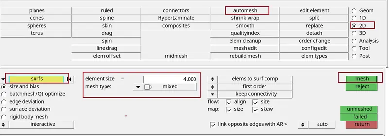
We can Modify mesh flow by changing surfaces to elements and select the elements. And also, we use rebuild mesh tool to improve our mesh flow.
Things need to be ensured while meshing
- Avoid back-to-back trias.
- Avoid opposite trias.
- Avoid trias element at the edges.
- To fix Elements quality Criteria and trias are removed by using Tool >> edit element, >> split, >> replace, >> elem clean up.
Best way to fix Quality By using Command: 2D >> quality index >> element optimize >> left click on element which are neighbour of quality failing element >> and quality is fix. Here we all option (figure below ) to fix quality.
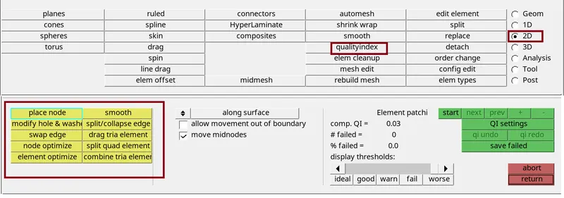
- The 'split quad element' tool is used to split a quad into two trias, this is useful because the trias can be used to form quads in other places.
- The 'drag tria element' is used to move the tria elements in the mesh, two opposite trias can be moved together so that they form a quad element.
- The 'place nodes' tool is used to move the nodes of the element so that their shape can be changed or slight adjustments can be made.
- The 'combine tria elements' tool is used to combine two adjacent tria elements, but this can also be achieved by using the 'drag tria element'.
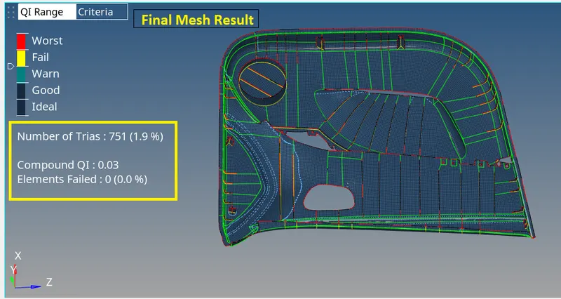
- Mesh results:
- Assigning Thickness to component:
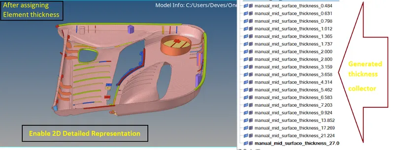
After meshing and after fixing quality failing element our next objective is to assigning thickness to our element. For this we use Command: Mesh >> Assign >> Mid mesh thickness >> and edit the card as shown below.
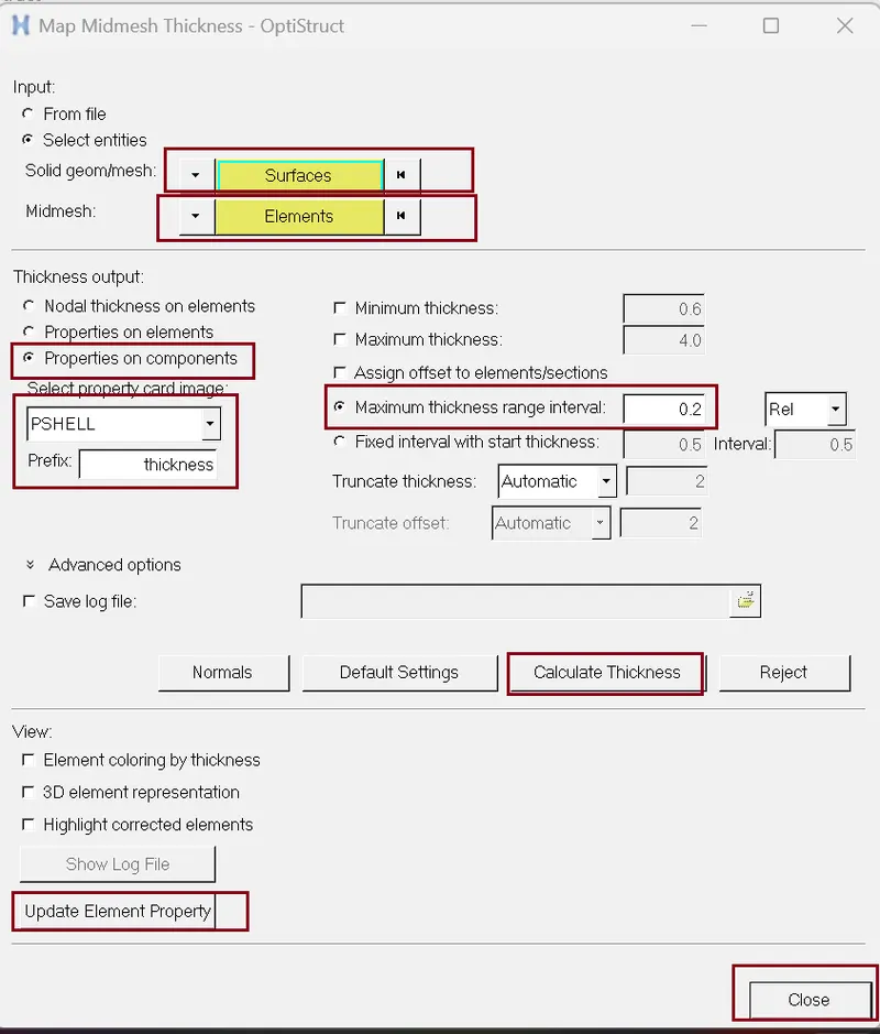
Selecting surface is our Parent surface and selecting element will our mesh result.
CONCLUSION:
Here we done Geometry clean-up, mid-surface extraction, Feature capturing and 2D meshing over “Side Door Panel”. All the features in the model are captured properly with good mesh flow, all the elements pass the quality criteria, at the end we are able to assigning thickness using Hyper mesh.
Learning outcome: -
- How to capture features.
- How to clean up the geometry of given components.
- How to Extract Mid – Surface.
- How to use offset tool to create mid surface.
- How to use geometrical tool to extract mid surface.
- Some basic Command like – edit element, split, replace, element clean up, Quality index, mask- unmask etc.
- How to assign thickness.
- How to check free edges.
- How to check Normal