Week - 5 - 2D meshing for Plastic components
1.
For the given Plastic Bottle Cap model, check for the geometrical errors and take the mid surface by suitable mid surfacing techniques. PID and Thickness assignment has to be done for all the mid surfaces. Mesh the same with the given element Quality criteria. (Refer to the table below for the Quality criteria)
|
S.No |
Quality Criteria |
Value |
|
1 |
Target/Average length |
1 |
|
2 |
Minimum Length |
0.5 |
|
3 |
Maximum Length |
3 |
|
4 |
Aspect |
3 |
|
5 |
Warpage |
15 |
|
6 |
Skewness |
45 |
|
7 |
Jacobian |
0.7 |
|
8 |
Minimum Quad Angle |
45 |
|
9 |
Maximum Quad Angle |
135 |
|
10 |
Minimum Tria Angle |
30 |
|
11 |
Maximum Tria Angle |
120 |
|
10 |
Tria Percentage |
15 |
1. Target element length:
It is the size of the element by which we can get the most nearer approximate value of the result compared to the experimental result.
2. Minimum element length:
The minimum element length is given by the instructor for the reason of quality criteria to avoid the presence of any zero-length element. It is very important to check for crash analysis.
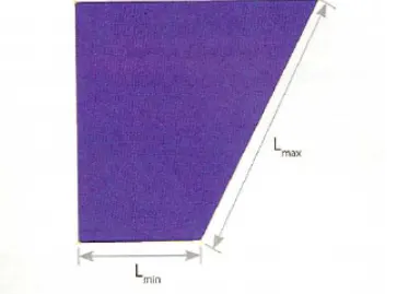
3. Aspect ratio:
The aspect ratio is defined as the ratio of max element edge length to the minimum element edge length. The ideal value for aspect ratio is 1 but less than 5 is acceptable.
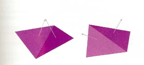
4. Wrap angle:
Wrap angle is defined as the angle between normal of the two planes by splitting the quad elements along the diagonal. Therefore the maximum angle allowed between the two possibilities is called the wrap angle. The ideal value is 0 degree but less than 10 degrees is acceptable for good practices.
The wrap is not applicable in the triangular element.
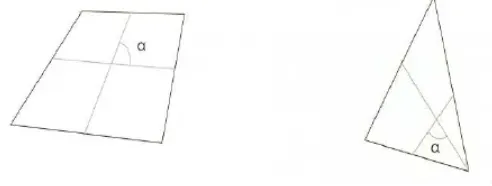
5. Skewness:
If the quad element is not square and has deformation then the skewness defined as the minimum angle between the two lines joining the opposite mid sides of the element similarly for the triangular element it is 90 minus between the line from each node to the opposing mid-side. The ideal value is 0 but less than 45 degree is acceptable
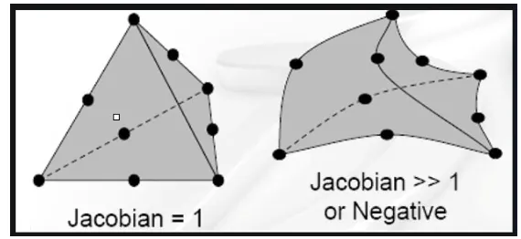
6. Jacobian:
Jacobian is the scale factor used in the transformation of a co-ordinated system. This is used for a faster analysis point of view. The ideal value is 1 but greater than 0.6 is acceptable.
It is global to the local coordinate system.
METHODOLOGY:
- Importing the CAD geometry that should be performed by transferring .stp file to ANSA readable file .ansa
- Cleaning up all the topological errors like single cons, triple cons, cracks, needle faces, overlapping faces, and unchecked faces. These errors encountered when transforming from one extension to another (ANSA readable).
- Perform geometry checks and clear all the topological errors.
- Take mid surfacing of each component using offset in ANSA tool, and Mid surface option in ANSA tool is used to take the mid surfacing of the total component present in that model. Then setting up property identities (PID's), and material identities (MIDs) for each individual component.
- Perform 2D meshing with mixed elements like a quadrilateral and triangular.
- Quality criteria should be followed as per the given question and checking the quality of the mesh with a specified aspect ratio, skewness, warpage, average length, minimum length, and maximum length, etc.
PROCEDURE:
STEP-1
- First, we want to open it then we import the CAD model by using the File->open option and select the Bottlecap. ansa hence the model will appear in the graphical area that is shown below,
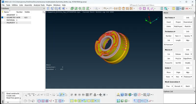
- After the model import switch on all the cons in the model by switching on all the options in the FACES DRAW bar. This will help in viewing the surface connection in a deatail.
2.Geometry check and mid surface extraction.
It is time consuming to check the surfaces of the model manually, so to speed up the geometrical check up checks option from tools is used TOOLS > CHECKS > GEOMETRY > EXECUTE
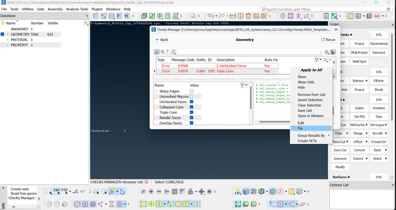
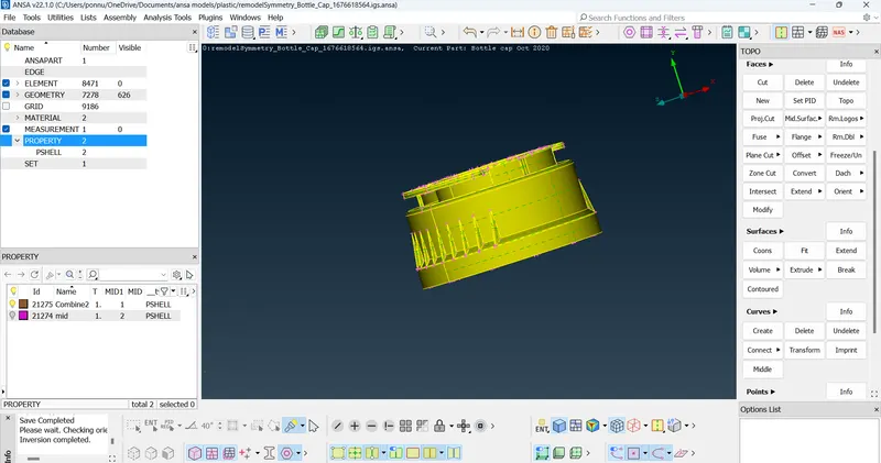
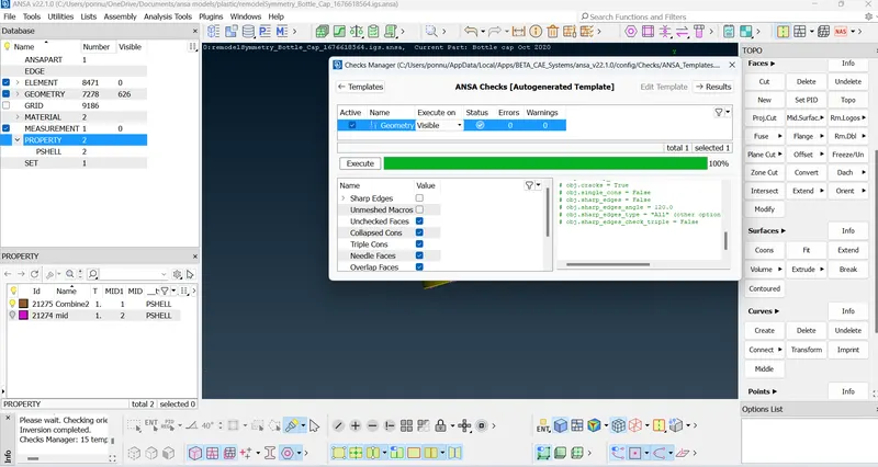
The model has some minor errors which can be fixed automatically fixed.
SELECT THE ERRORS > RIGHT MOUSE CLICK > FIX, this will clear the errors, if errors still exist, manual cleanup needs to be carried out by releasing the cons and fixing the damaged face and performing the topo to fix the free edges.
Mid surface extraction.
Before mid-surface extraction check the thickness of the component if it has a varying thickness, then the best way to extract the mid-surface is by manual mid-surfacing.
When the model has varying thickness ANSA algorithm fails to capture the proper geometry, hence the manual mid-surfacing is carried out.
To measure the thickness go to UTILITIES > MEASURE > select the points.
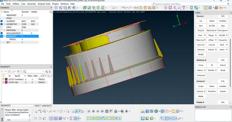
The given model is a plastic component that has a varying thickness, hence manual mid-surfacing is performed, by extracting individual mid-surface form faces of different thicknesses.
It helps in cutting the faces passing through each other, it creates a cut on the faces which are intersecting each other
For parts with varying thickness, cons are used to create the middle curve and using the middle curve mid face is generated using FACES > NEW
After creating the mid surface, divide the mid surface and apply the appropriate property with thickness to both the faces
final mid-surface with varying thickness property cards apllied to the mid-surfaces.
Geometry cleanup for meshing the generated mid-surface, Run the geometry check again on the mid-surface and fix the issues.
4. Quality criteria setup and Meshing.
set up the quality criteria for the meshing, go to UTILITIES > QUALITY CRITERIA
To start the meshing switch to Mesh module bar in the modules menu bar
some of the most used options in meshing process are highlighted in the below image.
Using these common parameters repeatedly a 2D mesh passing all the quality can be generated, to start meshing the surface go to MESH GENERATION > BEST and select the surface to be meshed.
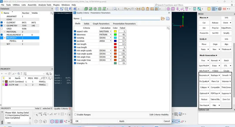
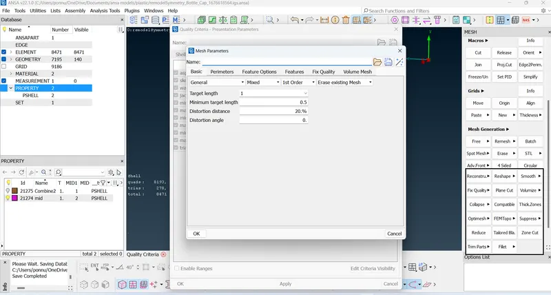
the number of tria elements in the model is below the threshold value of 15% with just 135 tria elements in the model.
5.Quality check.
The meshed part can be checked for quality criteria by switching the drawing styles to hidden modehe meshed part can be checked for quality criteria by switching the drawing styles to hidden mode, at some areas where two different triple cons are present the elements fail due to minimum element length which can not be solved, hence there are some off elements present in the mode
cons too near to eachother elements failuer can not be avoided in thses areas.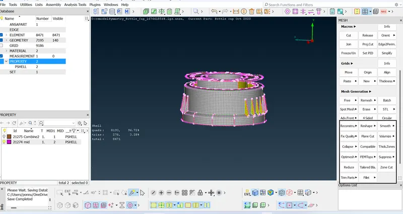
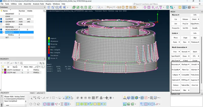
final element quality.
total of 45 elements have failed for the quality criteria which accounts to 0.45% of total elements.
Drawing shell as solid and checking the applied thickness to the master model.
from the above images it can be seen that the entire geometry has been captured with proper thickness values.
Learning outcomes:
Mid-surfacing of plastic components, manual mid-surfacing, varying thickness application
Conclusion:
Generated mid-surface for the given plastic component and 2D meshing is performed on the midsurface and property cards with different thickness are created and applied to the appropreate faces.