Week 4 - 2D Meshing for Sheet Metal
AIM:
For the given CCB CAD model, Check for the Geometry cleanup (if required), Take the mid surface, and Mesh it with the below 2D element Quality criteria.
GIVEN:
|
S.No |
Quality Criteria |
Value |
|
1 |
Target/Average length |
5 |
|
2 |
Minimum Length |
3 |
|
3 |
Maximum Length |
7 |
|
4 |
Aspect |
3 |
|
5 |
Warpage |
15 |
|
6 |
Skewness |
45 |
|
7 |
Jacobian |
0.7 |
|
8 |
Minimum Quad Angle |
45 |
|
9 |
Maximum Quad Angle |
135 |
|
10 |
Minimum Tria Angle |
30 |
|
11 |
Maximum Tria Angle |
120 |
|
10 |
Tria Percentage |
15 |
PROCEDURE:
First, the model is imported into the ANSA. The hood model contains five individual components as shown below.
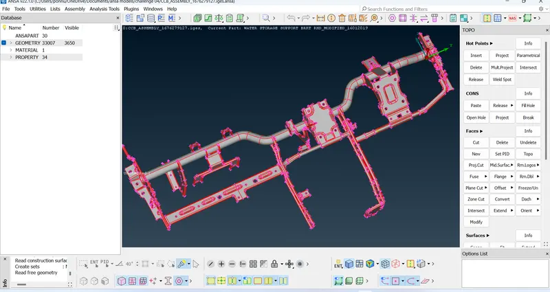
Refine the model using the length option under perimeters in the Mesh module. This will help to visualize the features in the model more properly. After refining the model perform a topo operation on the whole cad to stitch the closeby single cons together. Perform a geometry check using the checks option to find any existing geometric errors. All the geometric errors need to be cleared before moving forward to the next stage, which is the mid-surface generation.
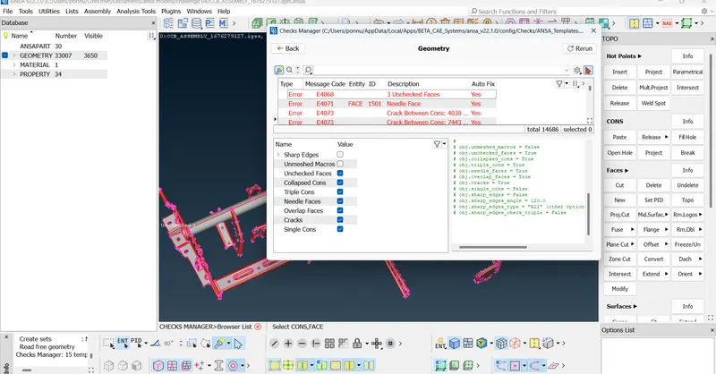
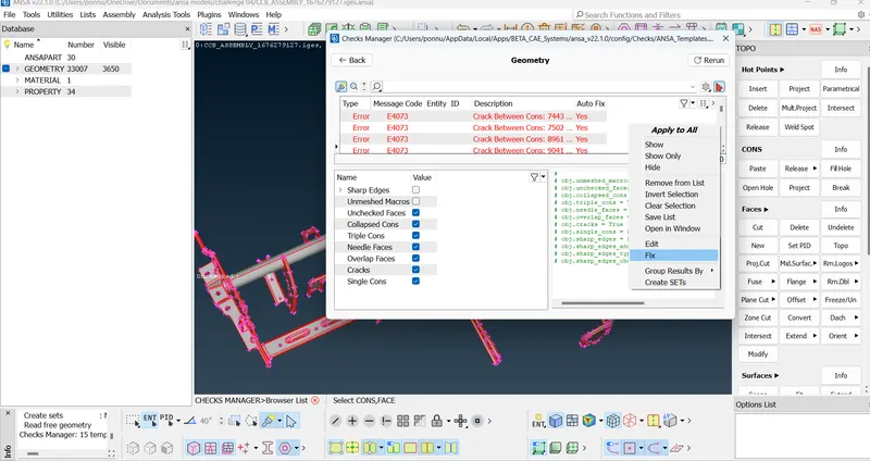
After clearing the geometric errors, perform the check again to confirm.
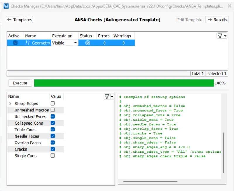
Now that all the errors have been cleared, we can start generating the mid-surface for each of the components of the assembly. Measure the thickness at all regions for placing the mid-surface at the correct distance. The components are found to be of uniform thickness, thus, we can use the skin option also to generate the mid-surfaces automatically.
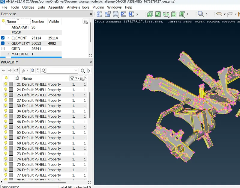
After generating all the mid-surfaces, the next step is meshing. Prior to meshing, define the required quality criteria.
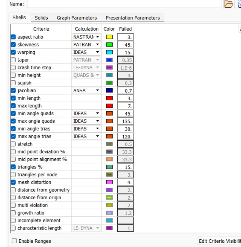
Mesh all the mid-surfaces to qualify the quality criteria and confirm the same by viewing the model in hidden mode. Make sure to create a zone cut around all bolt holes. Do not forget to apply thickness.
. First, the shell element length is altered by going to Perimeters>Length and all the CONS are selected and target element length 5 is fed as length value. The same is done for all the Macros (surfaces).
Next, all the areas are checked for minimum element length and altered where elements might fail for minimum length. Similarly, CONS which are not essential to define a feature are removed by joining the surfaces using the Macros>Join tool. Also, the complete mid surface model is divided strategically into sections
Next, meshing is done using the Mesh generation>Best tool. This tool generates the mesh using the best algorithm applicable. Then, the created mesh is refined using the Shell Mesh>Reconstruct tool. It is ensured that there are no rotating quads. Also, trias are kept as low as possible. While dealing with trias, the following things need to be ensured.
- No back to back trias touching each other
- No opposite trias
- No trias touching the edges
- No trias on a feature
- Low concentration of trias in a region
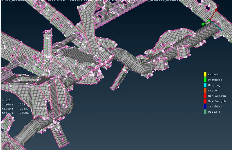
After modifying the mesh, Shell Mesh>Smooth tool is used to smoothen the flow of the mesh. Any elements failing for quality criteria are also fixed by either remeshing or smoothing the elements. The created mesh is shown below,
CONCLUSION:
Geometry cleanup, mid surface extraction, and 2D meshing of the given hood model were successfully done. And all the elements pass the quality criteria. All the features in the model are captured properly with good mesh flow. Tria concentration is kept low.