Project-2-Meshing of Door Inner Panel Challenge
Aim:
1) To mesh the given automobile side door interior plastic component in hypermesh with the quality criteria given below.
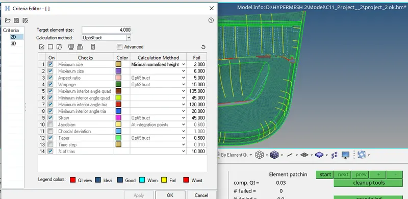
| S.No | Quality Criteria | Value |
| 1 | Aspect Ratio | 5 |
| 2 | Skewness | 45 |
| 3 | Warping | 15 |
| 4 | Taper | 0.5 |
| 5 | Min. Length | 2mm |
| 6 | Max. Length | 6mm |
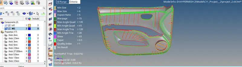
| 7 | Min angle Quad | 45 |
| 8 | Max angle Quad | 135 |
| 9 | Min angle Tria | 20 |
| 10 | Max angle Tria | 120 |
| 11 | Tria % | 10 |
| 12 | Target Element Length | 4mm |
2) To also assign thickness to the mid-surfaced and meshed components.
Theory:
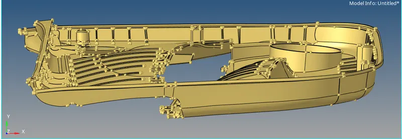
The model given to us is the Automobile Side Door Interior Plastic Component. These plastic are manufactured using the injection molding process in which the plastic in the molten form is injected into the mold or die to get the desired shape of the component. The material used in these interior parts is polypropylene which is high strength plastic material and it also has to the ability to absorb heavy loads in the event of a crash or an impact on to the body.
Procedure:
1) We first import the model into the hypermesh using the import model option.
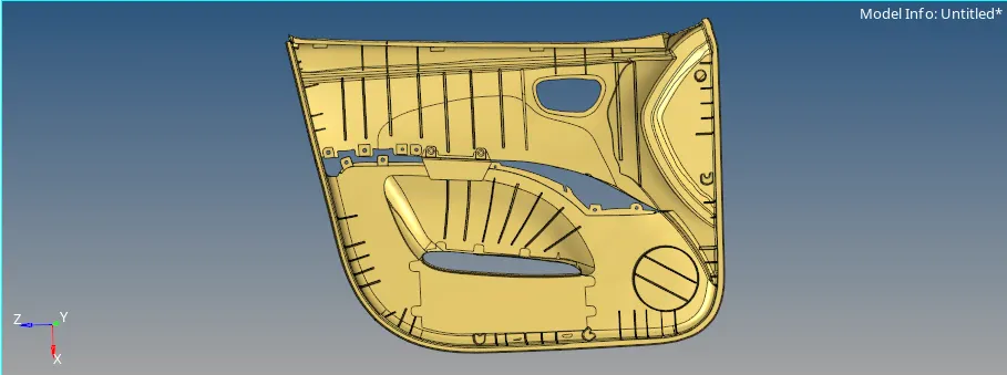
2) We see that the model is a plastic interior door trim model with complex geometry having clip-ons, ribs and dog houses as shown in the image given below.
3) We first defeature all the ribs with fillets and others curved parts with fillets such we can take good mid surface for it. For that, we use the Surface fillets option under defeature option of the Geometry module, first we select all the edges of the ribs and click on the find and the software finds the edges there are required to be defeatured and then, we click on remove which removes the fillets. T
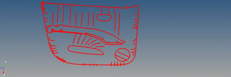
4) We then, measure the thickness of base part using the Distance option under Geometry module and extract mid surface only for it using the offset option under the Surface edit panel of the Geometry module. The offset option is shown in the image given below.
5) After that, we extract the mid surface for all the ribs, cylindrical component and mounting clips in the same method i.e. the offset+plane+sweep method. This time, we seggregate the components like ribs, cylindrical component and mounting clips according to their thickness so that, it would be easy for us while meshing the component.
6) After extracting the mid-surface for all the ribs, cylindrical component and mounting clips we need to extend them to the base surface so, that the connectivity is maintained through out the mid-surfaced component while meshing the component. For that, use the extend command under the Surface edit panel of the Geometry module. We input the extension distance and the surface onto which we have to extend the components and then, we press on extend. All the ribs, cylindrical component and mounting clips are extended to the base as shown in the image given below.
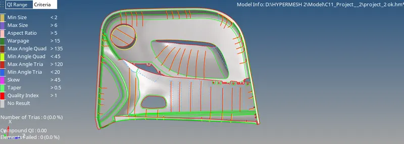
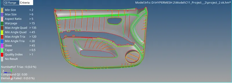
7) We then, proceed for meshing the component but before that we import the quality criteria as given in the aim for the meshing the model using the Criteria File Settings under the Preferences tab. The quality criteria is shown in the image given below.
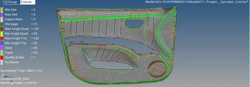
8) We start meshing the model component by component. We first mesh the base surface using the Automesh option under the 2D module. We first enter the target element length as 4mm with type of mesh as mixed and then select the surface to mesh and finally, click on mesh. We obtain mesh with some quality issues which we clear it once we mesh all the components. The automesh option is shown in the image given below.
9) We also mesh all the ribs and cylindrical surface and then, we go to the quality index option under 2D module to clear all the quality issues that we are facing in the model. We use all the QI cleanup tools to get rid of all the quality issues. Then, we can also use the Rebuild mesh, Smooth and elem cleanup options in the 2D module so that, we can obtain better mesh with lesser tria concentration. The options illustrated above are shown in the images given below.
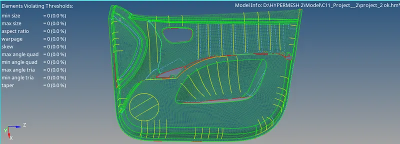
10) We then, get a good quality mesh over the whole model with no quality issues as shown in the image given below.
11) We, then proceed to create properties and material for all the mid-surfaced components. For that, we first create material by right clicking on the browser tree window and then click on create material. After crearting the material, we create properties for each of the mid-surfaced components according to thickness of each component by right clicking on the browser tree window and then click on create property. Property and material created are shown in the images given below.
12) After creating all the properties and materials we assign them to those properties and material to the mid-surfaced component as shown in the image given below.
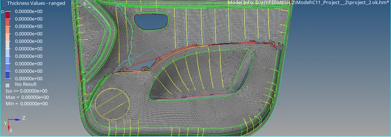
13) Finally, we assign thickness to all the components using the 2D element representation as detailed representation in the visualization tab as shown in the image given below.
Conclusion:
1) We have done the geometry cleanup.
2) We have taken the mid-surface for all the components using the offset option.
3) We have also meshed the mid-surfaced components one by one and then, cleared all the quality issues using QI cleanup tools, Rebuild mesh, Smooth and elem cleanup options.
4) We have finally, assigned thickness to the model by creating properties and material for each component. The thickness assignment was done using the 2D detailed element representation option.