Project 2 - Measuring the distance of an object using ultrasonic sensor and also smoothen the sensor data using moving average filter
Project 2 - Measuring the distance of an object using ultrasonic sensor and also smoothen the sensor data using moving average filter
Aim:
The aim of this project is to measure the distance travelled by a wave using an Ultrasonic Distance Sensor, apply a moving average filter to smoothen the sensor data, convert the distance measurement to inches, and display the distance in inches on an LCD display.
Description:
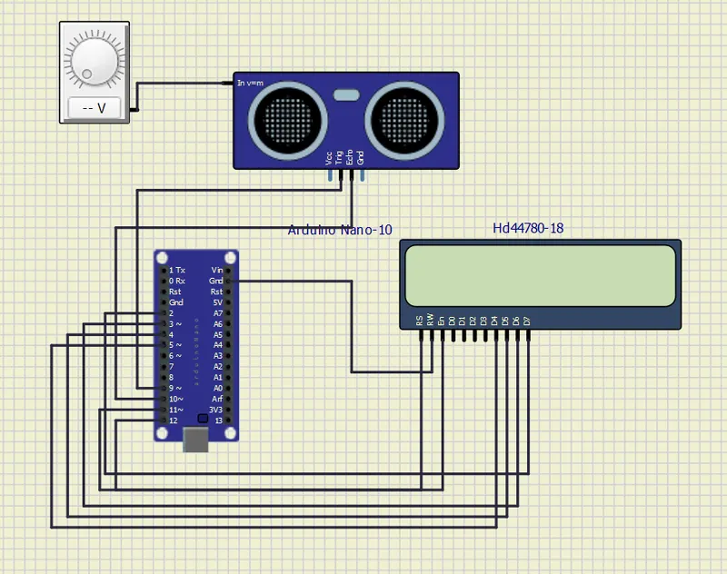
This project revolves around measuring distances using an Ultrasonic Distance Sensor. The sensor emits ultrasonic waves that travel to an object and bounce back, enabling the calculation of the distance. To ensure accurate and reliable measurements, a moving average filter is employed. This filter smoothes out the sensor data by considering a window of readings, effectively eliminating high-frequency variations and noise. As a result, more stable and precise distance measurements can be obtained.
In order to enhance the usability of the distance readings, the measured distances are converted to inches. This conversion allows for easy interpretation and better compatibility with commonly used measurement units. The converted distance values are then displayed on an LCD screen, providing a clear and easily readable output. Users can conveniently observe and track the measured distances in inches, making the information more accessible and practical.
By combining the Ultrasonic Distance Sensor, moving average filter, and LCD display, this project enables accurate and user-friendly distance measurements. The smoothness of the sensor data ensures reliable readings, while the conversion to inches enhances the understanding of the distances being measured. The LCD display acts as an effective visual interface, presenting the measured distances in a clear and concise manner. Overall, this project offers a valuable tool for applications that require precise distance measurements in inches.
Note: For this project for varition of frequency I'm used voltage variable source used.
Ultrasonic Distance Sensor (28015 Ping)
The Parallax PING)))™ ultrasonic distance sensor provides precise, non-contact distance measurements from about 2 cm (0.8 inches) to 3 meters (3.3 yards). It is very easy to connect to microcontrollers such as the BASIC Stamp®, Propeller chip, or Arduino, requiring only one I/O pin. The PING))) sensor works by transmitting an ultrasonic (well above human hearing range) burst and providing an output pulse that corresponds to the time required for the burst echo to return to the sensor. By measuring the echo pulse width, the distance to target can easily be calculated.
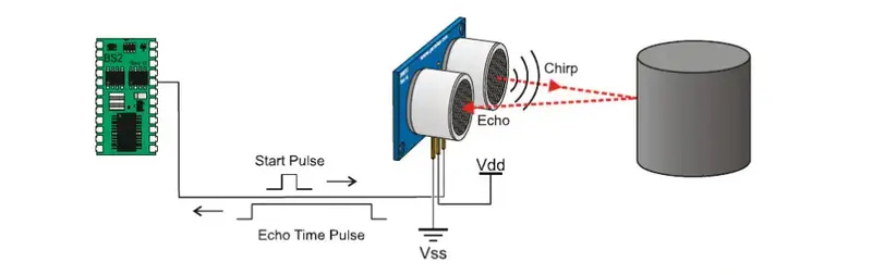
- Range: 2 cm to 3 m (0.8 in to 3.3 yd)
- Burst indicator LED shows sensor activity
- Bidirectional TTL pulse interface on a single I/O pin can communicate with 5 V TTL or 3.3 V CMOS microcontrollers
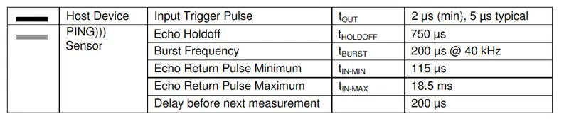
- Input trigger: positive TTL pulse, 2 µs min, 5 µs typ.
- Echo pulse: positive TTL pulse, 115 µs minimum to 18.5 ms maximum.
- RoHS Compliant
- Supply voltage: +5 VDC
- Supply current: 30 mA typ; 35 mA max
- Communication: Positive TTL pulse
- Package: 3-pin SIP, 0.1” spacing (ground, power, signal)
- Operating temperature: 0 – 70° C.
- Size: 22 mm H x 46 mm W x 16 mm D (0.84 in x 1.8 in x 0.6 in)
- Weight: 9 g (0.32 oz)
PIN Definitions:
| GND | Ground VSS |
| 5V | 5 VDC (Vdd) |
| SIG | Signal (I/O Pin) |
The PING))) sensor has a male 3-pin header used to supply ground, power (+5 VDC) and signal. The header may be plugged into a directly into solderless breadboard, or into a standard 3-wire extension cable (Parallax part #800-00120)
Communication Protocol:
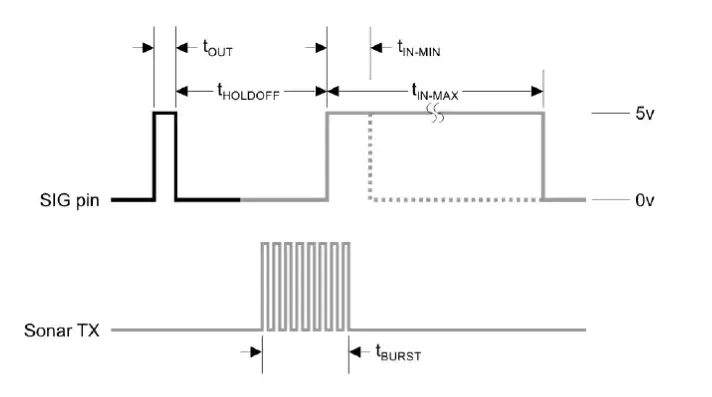
The PING))) sensor detects objects by emitting a short ultrasonic burst and then "listening" for the echo. Under control of a host microcontroller (trigger pulse), the sensor emits a short 40 kHz (ultrasonic) burst. This burst travels through the air, hits an object and then bounces back to the sensor. The PING))) sensor provides an output pulse to the host that will terminate when the echo is detected, hence the width of this pulse corresponds to the distance to the target.
Arduino UNO:
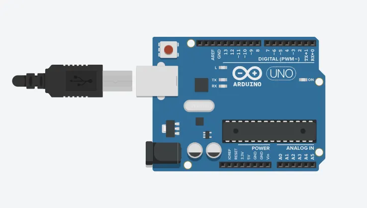
An Arduino is actually a microcontroller based kit which can be either used directly by purchasing from the vendor or can be made at home using the components, owing to its open source hardware feature. It is basically used in communications and in controlling or operating many devices. It was founded by Massimo Banzi and David Cuartielles in 2005.
Arduino Architecture:
Arduino’s processor basically uses the Harvard architecture where the program code and program data have separate memory. It consists of two memories- Program memory and the data memory.The code is stored in the flash program memory, whereas the data is stored in the data memory. The Atmega328 has 32 KB of flash memory for storing code (of which 0.5 KB is used for the bootloader), 2 KB of SRAM and 1 KB of EEPROM and operates with a clock speed of 16MHz.
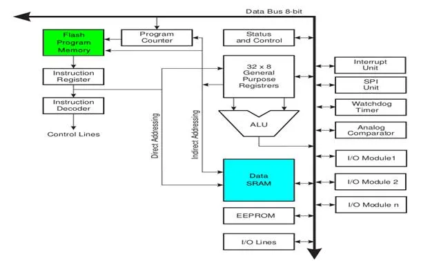
Arduino Pin Diagram:
A typical example of Arduino board is Arduino Uno. It consists of ATmega328- a 28 pin microcontroller.
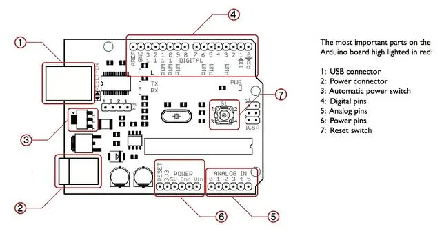
Arduino Uno consists of 14 digital input/output pins (of which 6 can be used as PWM outputs), 6 analog inputs, a 16 MHz crystal oscillator, a USB connection, a power jack, an ICSP header, and a reset button
Power Jack: Arduino can be power either from the pc through a USB or through external source like adaptor or a battery. It can operate on a external supply of 7 to 12V. Power can be applied externally through the pin Vin or by giving voltage reference through the IORef pin.
Digital Inputs: It consists of 14 digital inputs/output pins, each of which provide or take up 40mA current. Some of them have special functions like pins 0 and 1, which act as Rx and Tx respectively , for serial communication, pins 2 and 3-which are external interrupts, pins 3,5,6,9,11 which provides pwm output and pin 13 where LED is connected.
Analog inputs: It has 6 analog input/output pins, each providing a resolution of 10 bits.
ARef: It provides reference to the analog inputs
Reset: It resets the microcontroller when low.
How to program an Arduino?
The most important advantage with Arduino is the programs can be directly loaded to the device without requiring any hardware programmer to burn the program. This is done because of the presence of the 0.5KB of Bootloader which allows the program to be burned into the circuit. All we have to do is to download the Arduino software and writing the code.
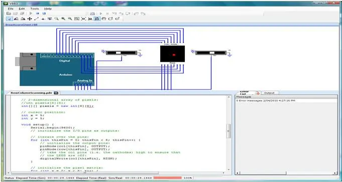
The Arduino tool window consists of the toolbar with the buttons like verify, upload, new, open, save, serial monitor. It also consists of a text editor to write the code, a message area which displays the feedback like showing the errors, the text console which displays the output and a series of menus like the File, Edit, Tools menu.
Steps to program an Arduino
Programs written in Arduino are known as sketches. A basic sketch consists of 3 parts
1. Declaration of Variables
2. Initialization: It is written in the setup () function.
3. Control code: It is written in the loop () function.
- The sketch is saved with .ino extension. Any operations like verifying, opening a sketch, saving a sketch can be done using the buttons on the toolbar or using the tool menu.
- The sketch should be stored in the sketchbook directory.
- Chose the proper board from the tools menu and the serial port numbers.
- Click on the upload button or chose upload from the tools menu. Thus the code is uploaded by the bootloader onto the microcontroller.
Few of basic Adruino functions are:
- Microcontroller: The Arduino Uno is powered by the ATmega328P microcontroller running at 16 MHz.
- Digital I/O Pins: It has a total of 14 digital input/output pins, with 6 of them capable of providing PWM (Pulse Width Modulation) output.
- Analog Inputs: The board has 6 analog input pins, marked as A0 to A5, which can also be used as digital I/O pins.
- Memory: The ATmega328P microcontroller on the Uno has 32KB of flash memory for storing the program, 2KB of SRAM, and 1KB of EEPROM.
- Communication: The Uno has a USB interface for connecting to a computer, allowing easy programming and serial communication. It also has a dedicated ICSP (In-Circuit Serial Programming) header for advanced programming and debugging.
- Power Supply: The board can be powered either through the USB connection or an external power supply. The recommended operating voltage is 5V.
- Compatibility: The Arduino Uno is compatible with a wide range of shields, which are expansion boards that provide additional functionality such as Wi-Fi, Bluetooth, motor control, and more.
- Programming: The Uno is programmed using the Arduino programming language (based on C/C++) and the Arduino IDE (Integrated Development Environment), which provides a simple and beginner-friendly interface for writing and uploading code.
Liquid Crystal Display
To interpret the inputs and the outputs of an Arduino program the easiest way is to display the output and inputs on the LCDs. There is a wide variety of displays available in the market which can be used for displaying the parameters of an Arduino program. The liquid crystal display having dimensions of 16×2 is mostly used as it is easier to interface with the Arduino boards, is cheaper and is easily available. This discourse briefly explains the 16×2 liquid crystal display module.
16×2 liquid crystal display (LCD)
The 16×2 liquid crystal display can be used in embedded systems where displaying a limited amount of data is necessary. This display comes with two lines of data and each line is divided into sixteen columns. Each row has a block of 8 rows and 5 columns also called cells or in other words we can say that each cell of the row has 40 pixels.
The LCD has a capacity of displaying 32 characters in two rows and these characters can be integers, alphabets or symbols. Similarly, the LCD can also display some user made characters as well by turning some dots of the cell on and off. In short there is a wide variety of characters that can be shown on the LCD.
Pin configuration for 16×2 LCD
There is a total of 16 pins of the 16×2 display module and explanation of each pin is mentioned below:
VSS pin : This pin is used for grounding the liquid crystal display.
VDD pin : To connect the LCD to the supply the VDD pin is used, and it is maximum 5 volts.
V0 pin : To adjust the brightness of the display module the V0 pin is used. Usually this is connected with the output of the potentiometer. Similarly, by varying the resistance of the potentiometer we can adjust the brightness of the LCD.
RS pin : To select between the command and the data register the RS pin is used. The command register is used to store the command given to LCD like function for clearing the LCD, function for setting the position of the cursor and many more.
Similarly, to display the data on the LCD screen the data register is used which stores this data. So, when the data is to be displayed the value for the RS pin becomes 1 and when the command is to be sent the value for the pin becomes 0.
RW pin : This pin is used for reading and writing the data into the register which is then displayed on the LCD. When there is no data for writing the register the pin will be in reading mode that is its state will be 0. Similarly, when there is data to be written then the state of the pin will be 1. Normally this pin is grounded because mostly the read register is used for only displaying the data.
E pin : This pin is also called the enable pin of the module as it sends the signal to the LCD. This pin sends the data to the data pins of the LCD when the data is to be sent on the LCD. This pin has a high state that is 1.
Data pins : The 16×2 LCD has a number of 8 pins for receiving and sending the data and mostly the only four data pins are used as it requires less pins of the device that is to be interfaced. The liquid crystal module works in two modes one is the 8-bit and the other is the 4-bit mode.
In the 8-bit mode all the 8 data pins are used and the data of 8 bits can be transferred simultaneously. However, in 4- bit mode the 8-bit data is divided into two parts that are 4-bit for each part, but this mode requires less number of pins.
A and K pins : The A pin can also be called as anode pin for the LCD as it is used to supply power to the backlight of LCD module and the K pin is cathode pin for the LCD as it is connected to the ground terminal.
To summarize the pin configuration we have given a table for the the pins of the 16×2 LCD
| Pin | Name | Description |
| 1 | VSS | Pin used for grounding the LCD |
| 2 | VDD | Pin used for connecting voltage supply with LCD |
| 3 | V0 | Pin used for controlling the brightness of the display module |
| 4 | RS | Pins for selection of data and command register |
| 5 | RW | Pin for using the write register of LCD |
| 6 | E | Pin used for sending the data to the data pins of LCD |
| 7-14 | D0-D7 | Data pins of the LCD |
| 15 | A/LED+ | Anode for the backlight of LCD |
| 16 | K/LED- | Cathode for the backlight of LCD |
The LCD (Liquid Crystal Display) is a visual output device used in this project to display temperature readings from multiple rooms. It is a 16x2 character LCD, meaning it can show 16 characters per line and has two lines.
The LCD is connected to the Arduino board using several digital pins for data and control signals. The connections typically include pins for RS (Register Select), EN (Enable), and D4-D7 (Data). The VCC pin is connected to the 5V power supply, and the GND pin is connected to ground.
The Arduino code utilizes the "LiquidCrystal.h" library to initialize the LCD and control its functions. The code sends commands and data to the LCD to display temperature readings received from the slave nodes. The temperature values, along with corresponding room identifiers, are formatted and displayed on the LCD screen.
By incorporating the LCD, users can easily monitor and observe the temperature variations in different rooms, enhancing the usability and effectiveness of the temperature measurement system.
An LCD (Liquid Crystal Display) is a common display technology used in various electronic devices, including Arduino projects. It provides a visual interface to display text, numbers, and other information. In this project, an LCD is utilized to show the temperature readings from different rooms.
The LCD used is a 16x2 character LCD, which means it can display 16 characters per line and has two lines. It uses a Hitachi HD44780 controller, which simplifies interfacing with the Arduino board.
To connect the LCD to an Arduino board, you typically need to make the following connections:
- RS (Register Select): Connects to a digital pin on the Arduino. It selects the data register (RS=HIGH) or the command register (RS=LOW) of the LCD.
- EN (Enable): Connects to a digital pin on the Arduino. It enables or triggers the execution of commands or data sent to the LCD.
- D4-D7 (Data): Connects to four digital pins on the Arduino. These pins send the data bits (4-bit mode) to the LCD for displaying characters.
- VCC (Power): Connects to the 5V pin on the Arduino to provide power to the LCD.
- GND (Ground): Connects to the GND pin on the Arduino to complete the circuit.
The connections can vary depending on the specific LCD module and Arduino board used. It's important to refer to the datasheets or pinout diagrams for the LCD and the Arduino board to ensure the correct wiring.
In the Arduino code, you need to include the appropriate LCD library, such as the "LiquidCrystal.h" library. This library provides functions to initialize the LCD, set the cursor position, and print text or numbers on the display.
By utilizing the LCD in this project, the temperature readings obtained from the slave nodes are displayed in a clear and readable format, allowing users to monitor the temperature of different rooms at a glance.
Code:
#include"Arduino.h"
#include <LiquidCrystal.h>

const int trigPin = 9;          // Trigger pin of the ultrasonic sensor
const int echoPin = 10;         // Echo pin of the ultrasonic sensor
const int windowSize = 5;       // Size of the moving average window

unsigned long duration;         // Duration of the wave travel
float distance;                 // Distance travelled by the wave
float totalDistance;            // Total distance for moving average calculation
float distanceBuffer[windowSize]; // Buffer to store distance readings

LiquidCrystal lcd(12, 11, 5, 4, 3, 2);   // LCD display pin assignments

void setup() {
  pinMode(trigPin, OUTPUT);
  pinMode(echoPin, INPUT);

  lcd.begin(16, 2);         // Initialize the LCD display
  lcd.print("Distance:      ");

  for (int i = 0; i < windowSize; i++) {
    distanceBuffer[i] = 0;  // Initialize the distance buffer with 0 values
  }
}

void loop() {
  // Measure distance using Ultrasonic Sensor
  digitalWrite(trigPin, LOW);
  delayMicroseconds(2);
  digitalWrite(trigPin, HIGH);
  delayMicroseconds(10);
  digitalWrite(trigPin, LOW);
  duration = pulseIn(echoPin, HIGH);
  distance = duration * 0.0133 / 2;   // Calculate distance in inches

  // Calculate moving average
  totalDistance -= distanceBuffer[0];     // Remove the oldest reading from the total
  totalDistance += distance;              // Add the latest reading to the total

  // Shift the distance buffer to accommodate the new reading
  for (int i = 1; i < windowSize; i++) {
    distanceBuffer[i - 1] = distanceBuffer[i];
  }
  distanceBuffer[windowSize - 1] = distance; // Store the latest reading in the buffer

  float averageDistance = totalDistance / windowSize; // Calculate the moving average

  // Display the Distance on LCD
  lcd.setCursor(9, 0);
  lcd.print(distance);
  lcd.print(" in");
  lcd.setCursor(0, 1);
  lcd.print("Avg: ");
  lcd.print(averageDistance);
  lcd.print(" in");

  delay(100);    // Delay for stability
}
Result:
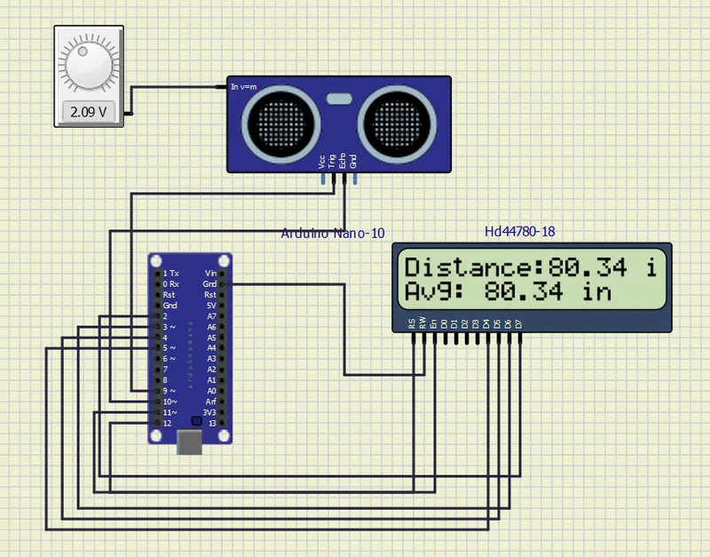
The implemented project successfully measures distances using an Ultrasonic Distance Sensor. By employing a moving average filter, the sensor data is smoothened, resulting in more reliable and accurate distance readings. The use of this filter eliminates high-frequency variations and noise, providing stable measurements.
The measured distances are converted to inches, which enhances the usability and compatibility of the data. This conversion allows for easy interpretation and better integration with commonly used measurement units. The converted distances are then displayed on an LCD screen, providing a clear and readable output for users to observe and track the measured distances.
Overall, this project delivers precise distance measurements in inches, with a focus on accuracy and usability. The combination of the Ultrasonic Distance Sensor, moving average filter, and LCD display creates an effective distance measurement system that can be utilized in various applications requiring accurate distance readings in inches.