Project 2 - Measuring the distance of an object using ultrasonic sensor and also smoothen the sensor data using moving average filter
# Solution:-
Project 2 - Measuring the distance of an object using ultrasonic sensor and also smoothen the sensor data using moving average filter.
Objective: - In this project we have to implement the code for “Measuring the distance of an object using ultrasonic distance sensor (28015 Ping) and also smoothen the sensor data using moving average filter”.
Goals:-
- Measuring the distance in terms of inches of an object using Ultrasonic Distance Sensor (28015 Ping).
- The sensor data is smoothened by using Moving average filter technique to eliminate the high frequency variations from the sensor data.
Key Highlights of the Project:
- Measuring the distance travelled by the wave to the object and gets bounced back from the object to sensor.
- Smoothening of the sensor data by moving average filter technique, the filter has a window of certain size. That window determines that how many data the filter can take.
Deliverables of this project:-
- The distance travelled by a wave to the object for which we want to measure the distance using Ultrasonic Distance Sensor (28015 Ping).
- Eliminate the high frequency jitters from the sensor data by Moving Average filter to smoothen the sensor data.
Expected Outcomes:-
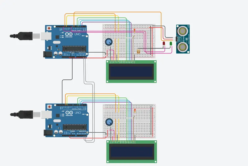
Here we get the Knowledge of Ultrasonic sensor (28015 Ping), that is how can we use this sensor to measure the distance travelled by wave to the object, the hardware connection of 2 Arduino’s connected to the sensor and smoothening the sensor data by removing high frequency variations using Moving Average Filter Technique.
Overview of this Project:-
Ultrasonic sensors are great tools to measure distance and detect objects without any actual contact with the physical world. It is used in several applications, like in measuring liquid level, checking proximity and even more popularly in automobiles to assist in self-parking or anti-collision systems. In this project, we have used the PING 28015 Ultrasonic Sensor with Arduino to determine the distance of an obstacle from the sensor. The basic principle of ultrasonic distance measurement is based on ECHO. When sound waves are transmitted in the environment then waves return back to the origin as ECHO after striking on the obstacle. So we only need to calculate the traveling time of both sounds means outgoing time and returning time to origin after striking on the obstacle. As the speed of the sound is known to us, after some calculation we can easily calculate the distance.
Here we used the Moving Average Filter concept to smooth the data that we get from PING ultrasonic sensors and after that we also use here I2C Communication protocol to send the message to the other Arduino that is worked here as a Master circuit.
Ultrasonic Sensor Module is PING 28015.
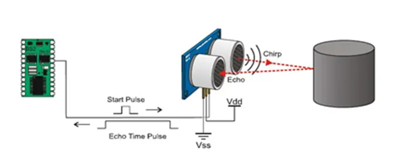
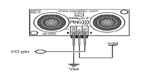
The Parallax PING ultrasonic distance sensor provides precise, non-contact distance measurements from about 2 cm (0.8 inches) to 3 meters (3.3 yards). It is very easy to connect to microcontrollers such as the BASIC Stamp, Propeller chip, or Arduino, requiring only one I/O pin. The PING sensor works by transmitting an ultrasonic (well above human hearing range) burst and providing an output pulse that corresponds to the time required for the burst echo to return to the sensor. By measuring the echo pulse width, the distance to target can easily be calculated.
Communication protocol of PING 28015
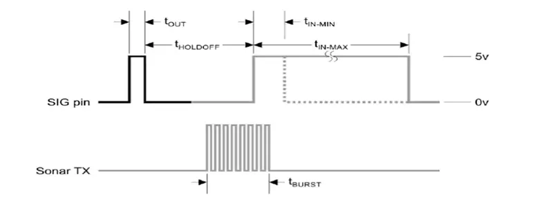
The PING sensor detects objects by emitting a short ultrasonic burst and then "listening" for the echo. Under control of a host microcontroller (trigger pulse), the sensor emits a short 40 kHz (ultrasonic) burst. This burst travels through the air, hits an object and then bounces back to the sensor. The PING sensor provides an output pulse to the host that will terminate when the echo is detected; hence the width of this pulse corresponds to the distance to the target.
Working Diagram of PING Ultrasonic sensor-
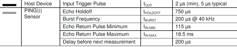
Timing Diagram:-
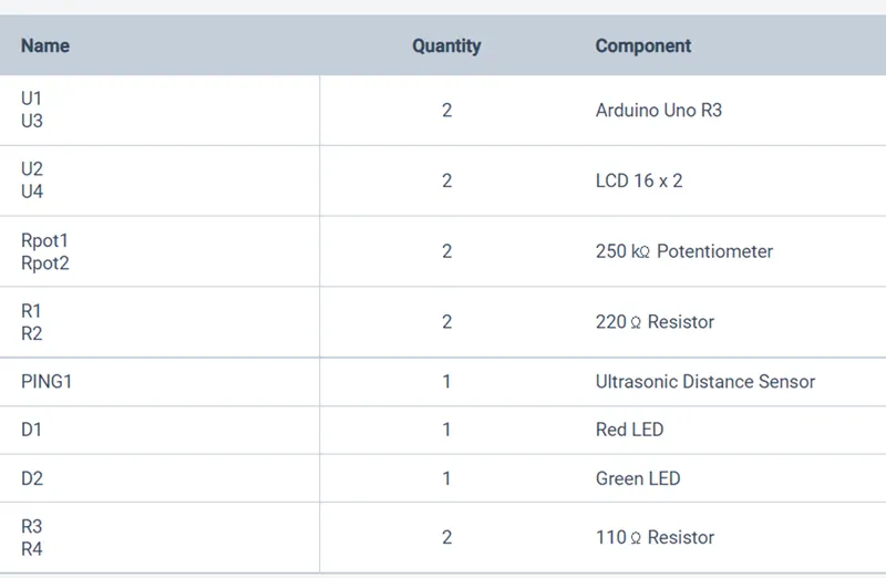
Component’s Used:-
Circuit Implementation:-
Moving Average Filter Concept: -
Moving Average Filter is a Finite Impulse Response (FIR) Filter smoothing filter used for smoothing the signal from short term overshoots or noisy fluctuations and helps in retaining the true signal representation or retaining sharp step response. It is a simple yet elegant statistical tool for de-noising signals in the time domain.
These filters are favorites for most Digital Signal Processing (DSP) applications dealing with time-series data. It is simple, fast, and shows amazing results by suppressing noise and retaining the sharp step response. This makes it one of the optimal choices for time-domain encoded signals.
The Moving Average filter is a good smoothing filter in the time domain but a terrible filter in the frequency domain. In applications where only time-domain processing is present Moving average filters shine, but in applications where information is encoded in both time and frequency or in frequency domain solely it can be a terrible option to choose.
Final code Implementation:-
/* Master circuit that receive the data and after applying

 * Moving average Filter here we are smoothing the data and

 * display it on the LCD Display.

 */

#include <Wire.h>     // Adding I2c protocol header file

#include <LiquidCrystal.h>  // adding LCD header file

#define window_size 5                       // defining a constant function windowsize


LiquidCrystal lcd_2(12, 11, 5, 4, 3, 2);// defining lcd pin

int index = 0;                 // int type variable index defined

int dis_sum = 0;             // int type variable distance sum defined

int distances[window_size];// int type array[index] defined

int Avg_dis = 0;          // int type variable Avg_dis defined


void setup()

{

  Serial.begin(9600);  // initialize the Serial Monitor

  lcd_2.begin(16, 2); // Set up the number of columns and rows on the LCD.

  lcd_2.setCursor(0,0);     // Sets Cursor at first line of Display

  lcd_2.print("Master Circuit");// Prints Master in LCD

  lcd_2.setCursor(0,1);     // Sets Cursor at second line of Display

  lcd_2.print("Ramlochan"); // Prints Ramlochan in LCD

  delay(5000);              // Delay for 5 seconds

  lcd_2.clear();            // Clears LCD display

  Wire.begin();             // initialize the I2c communication

  pinMode(13,OUTPUT);                   // pin no 13 assigned as Output

  pinMode(8,OUTPUT);                     // pin no 8 assigned as output

}


void loop()

{

  Wire.requestFrom(8,16);// requesting  data from the given slave

  // reading salve message and saving it into MasterReceive variable

  int MasterReceive = Wire.read();

  dis_sum = dis_sum - distances[index];// Remove the oldest entry from the sum

  distances[index] = MasterReceive;    // Add the newest reading to the window

  dis_sum = dis_sum + MasterReceive;   // Add the newest reading to the sum

  index = (index+1) % window_size; // Increment the index, and wrap to 0 if it exceeds the window size

  Avg_dis = dis_sum / window_size; // Divide the sum of the window by the window size for the result

  Serial.println("Signal after Filteration");// print message to serial monitor

  Serial.print(MasterReceive);

  Serial.println(" inch");

  lcd_2.setCursor(0, 1);

  // print the number of seconds since reset:

  lcd_2.print(MasterReceive);

  lcd_2.print("inch");

  // set the cursor to column 0, line 1

  // (note: line 1 is the second row, since counting

  // begins with 0):

  lcd_2.setCursor(0, 0);

  // print the number of seconds since reset:

  lcd_2.print("Filter distance");

  delay(100); // Wait for 100 millisecond(s)

  Wire.end();   // end of i2c communication

}
# Code for Slave that is reading the distance from PING sensor 28015
/* Slave circuit that checks the object distance using ultrasonic

 * distance sensor (28015 Ping) and send the data to the Master

 * Circuit.

 */


#include <Wire.h>     // Adding I2c protocol header file

#include <LiquidCrystal.h>  // adding LCD header file


LiquidCrystal lcd_1(12,11,5,4,3,2);// defining the pin of LCD

// this constant won't change. It's the pin number of the sensor's output:

const int pingPin = 7;

// establish variables for duration of the ping, and

// distance result in inches.

long duration, inches;


void setup() {

  // initialize serial communication

  Serial.begin(9600);

  lcd_1.begin(16, 2); //Set up the number of columns and rows on the LCD.

  lcd_1.setCursor(0,0);      //Sets Cursor at 0th line of Display

  lcd_1.print("Project No 2");//Prints message in LCD

  lcd_1.setCursor(0,1);     //Sets Cursor at second line of Display

  lcd_1.print("Slave Circuit"); //Prints message in LCD

  delay(5000);                //Delay for 5 seconds

  lcd_1.clear();                //Clearing the LCD display

  Wire.begin(8);                                 // initialize the I2c protocol

  Wire.onRequest(send);// call the send function to request byte

}


void loop() {


  // The PING))) is triggered by a HIGH pulse of 2 or more

  // microseconds.Give a short LOW pulse beforehand to ensure

  // a clean HIGH pulse:

  pinMode(pingPin, OUTPUT);

  digitalWrite(pingPin, LOW);

  delayMicroseconds(2);

  digitalWrite(pingPin, HIGH);

  delayMicroseconds(5);

  digitalWrite(pingPin, LOW);

  /* The same pin is used to read the signal from the PING))):

   * a HIGH pulse whose duration is the time (in microseconds)

   * from the sending of the ping to the reception of its echo

   * off of an object.

   */

  pinMode(pingPin, INPUT);

  duration = pulseIn(pingPin, HIGH);

  Serial.println("Object Distance");

  // convert the time into a distance

  inches = microsecondsToInches(duration);

  if(inches<131 && inches>=4)

  {

    digitalWrite(13, HIGH);

    digitalWrite(8, LOW);

  }

  else

  {

    digitalWrite(13,LOW);

    digitalWrite(8,HIGH);

  }

  Serial.print(inches);      // printing the message to the serial monitor

  Serial.println(" inch");

  lcd_1.setCursor(0,0);

  lcd_1.print("Object Distance");// printing the message to the lcd

  lcd_1.setCursor(0,1);

  lcd_1.print(inches);

  lcd_1.print("inch");

  delay(100);// providing the delay

}

long microsecondsToInches(long microseconds) {

  // According to Parallax's datasheet for the PING))), there are 73.746

  // microseconds per inch (i.e. sound travels at 1130 feet per second).

  // This gives the distance travelled by the ping, outbound and return,

  // so we divide by 2 to get the distance of the obstacle.

  return microseconds / 74 / 2;

}

void send(){

  Wire.write(inches); //To send message to Master

}
# Final Output:-
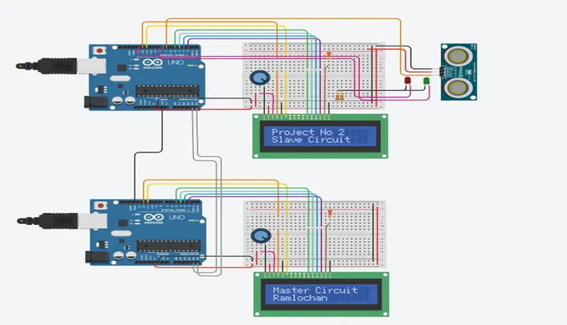
- Here we are seeing the output at the start of the circuit, that tells us what this circuit Introduction.
2.Here we get the object distance from 1st Arduino with the help of PING sensor and here we also attach a led that tells us that if object position is in the sensor range than green Led will glow otherwise if it’s out of range than Red will glow.
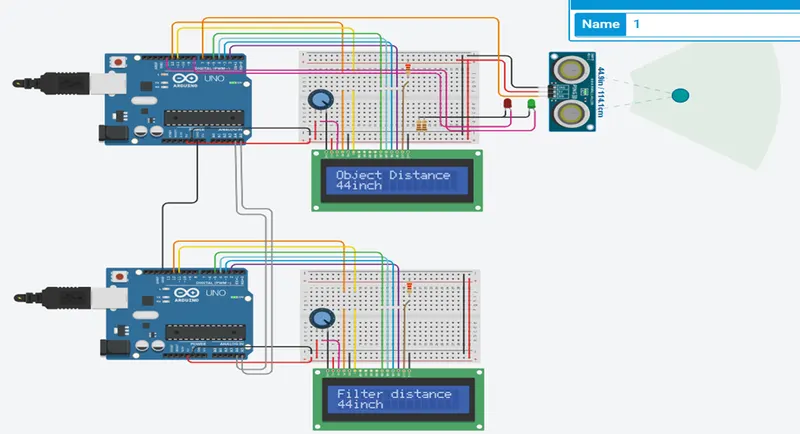
3.Here it’s showing that if any object is not detected in the range than it’s showing it’s by default value that is 131 inch in both the cases, that before filtration and after filtration.
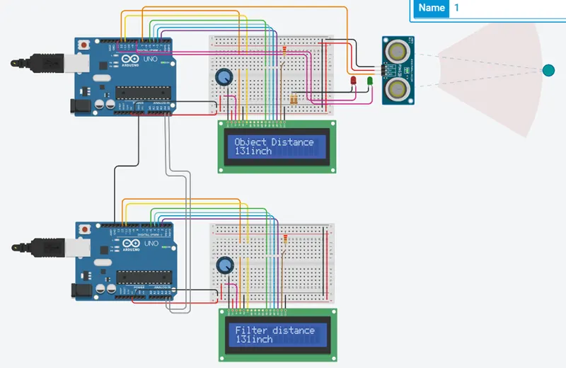
4. Here it’s showing the serial monitor output.
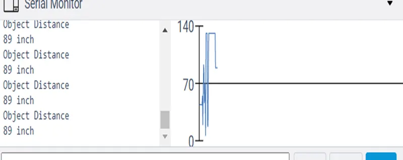
- Before filtration
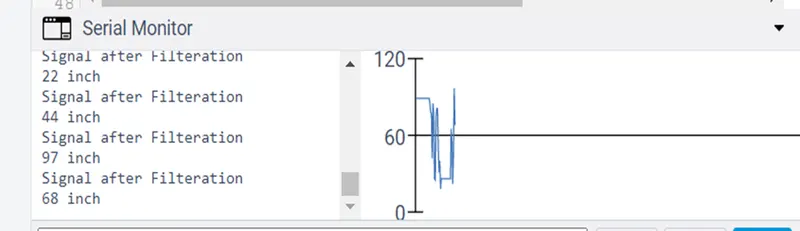
2. After filtration(after applying moving average filtration)
# Conclusion:-
Here we implement the object distance measurement circuit with the help of PING 28015 sensor, and we are able to know that how a ping sensor work, and also understood the moving average concept and also get a better idea about I2C communication working.
# References:-