Project 2 - Measuring distance of an object using ultrasonic sensor (HC-SR04)
Aim :
In this project, the implementation of code for “Measuring distance of an object using ultrasonic distance sensor (HC-SR04)
Goals:
- Measuring the distance of an object using Ultrasonic Distance Sensor (HC-SR04)
- Usage of Input Capture Mode
Key Highlights of the Project:
- Measuring the distance travelled by the wave to the object and gets bounced back from the object to sensor.
- Measuring Pulse width using Input Capture Mode
Introduction About Ultrasonic Sensor :
- An ultrasonic sensor is an instrument that measures the distance to an object using ultrasonic sound waves.
- An ultrasonic sensor uses a transducer to send and receive ultrasonic pulses that relay back information about an object’s proximity.
- High-frequency sound waves reflect from boundaries to produce distinct echo patterns.
- The ultrasonic sensor (or transducer) works on the same principles as a radar system. An ultrasonic sensor can convert electrical energy into acoustic waves and vice versa.
- The acoustic wave signal is an ultrasonic wave traveling at a frequency above 18kHz. The famous HC SR04 ultrasonic sensor generates ultrasonic waves at 40kHz frequency.
-
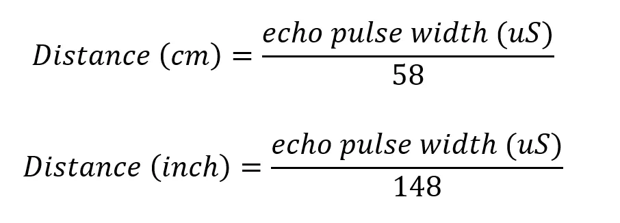
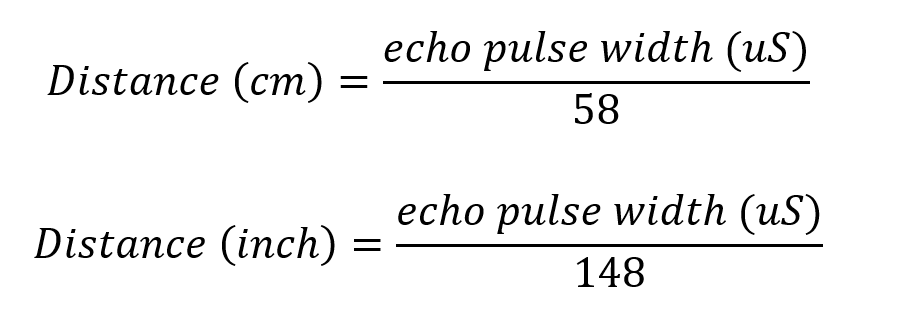
The microcontroller interprets the time signal into distance using the following functions:
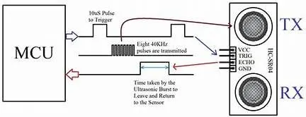
Sample image is givenn below to understand working of an Ultrasonic Sensor.
Code :
/*
 * AVR_Project_2.c
 *
 * Created: 10-07-2022 22:41:27
 * Author : chaudhari
 *
 */

#include <avr/io.h>
#define F_CPU 8000000UL
#include <avr/interrupt.h>
#include <util/delay.h>
#include <string.h>
#include <stdlib.h>

#define LCD_Data_Dir DDRD   // Define LCD data port direction
#define LCD_Command_Dir DDRC // Define LCD command port direction register
#define LCD_Data_Port PORTD  // Define LCD data port
#define LCD_Command_Port PORTC  // Define LCD data port
#define EN PC2   // Define Enable signal pin
#define RW PC3 // Define Read/Write signal pin
#define RS PC4   // Define Register Select  signal pin


void LCD_Command (char);   // LCD command write function
void LCD_Char (char);    // LCD data write function
void LCD_Init (void);   // LCD Initialize function
void LCD_String (char*);   // Send string to LCD function
void LCD_String_xy (char,char,char*);   // Send row, position and string to LCD function


void LCD_Command (char cmd)   // LCD command write function
{
	LCD_Data_Port = cmd;   // Write command data to LCD data port
	LCD_Command_Port &= ~((1<<RS)|(1<<RW));   // Make RS LOW (command reg.), RW LOW (Write)
	LCD_Command_Port |= (1<<EN);   // High to Low transition on EN (Enable)
	_delay_us(1);
	LCD_Command_Port &= ~(1<<EN);
	_delay_ms(3);    // Wait some time
}


void LCD_Char (char char_data)   // LCD data write function
{
	LCD_Data_Port = char_data;   // Write data to LCD data port
	LCD_Command_Port &= ~(1<<RW);   // Make RW LOW (Write)
	LCD_Command_Port |= (1<<EN)|(1<<RS);   // Make RS HIGH (data reg.) and High to Low transition on EN (Enable)
	_delay_us(1);
	LCD_Command_Port &= ~(1<<EN);
	_delay_ms(1);   // Wait little bit
}


void LCD_Init (void)   // LCD Initialize function
{
	LCD_Command_Dir |= (1<<RS)|(1<<RW)|(1<<EN); // Make LCD command port direction as o/p
	LCD_Data_Dir = 0xFF;   // Make LCD data port direction as o/p
	_delay_ms(20);   // LCD power up time to get things ready, it should always >15ms
	LCD_Command (0x38);   // Initialize 16X2 LCD in 8bit mode
	LCD_Command (0x0C);  // Display ON, Cursor OFF command
	LCD_Command (0x06);   // Auto Increment cursor
	LCD_Command (0x01);   // Clear LCD command
	LCD_Command (0x80);   // 8 is for first line and 0 is for 0th position
}


void LCD_String (char *str)   // Send string to LCD function
{
	int i;
	for(i=0;str[i]!=0;i++)   // Send each char of string till the NULL
	{
		LCD_Char (str[i]);   // Call LCD data write
	}
}


void LCD_String_xy (char row, char pos, char *str)   // Send string to LCD function
{
	if (row == 1)
	LCD_Command((pos & 0x0F)|0x80);   // Command of first row and required position<16
	else if (row == 2)
	LCD_Command((pos & 0x0F)|0xC0);   // Command of Second row and required position<16
	LCD_String(str);   // Call LCD string function
}

#define Trigger_pin PA0   // Trigger pin

int TimerOverflow = 0;


ISR(TIMER1_OVF_vect)
{
	TimerOverflow++;   // Increment Timer Overflow count
}


int main(void)
{
	char string[10];
	long count;
	double distance;

	DDRA = 0x01;   // Make trigger pin as output
	PORTB = 0xFF;   // Turn on Pull-up

	LCD_Init();
	LCD_String_xy(1, 0, "Ultrasonic");

	sei();   // Enable global interrupt
	TIMSK = (1 << TOIE1);   // Enable Timer1 overflow interrupts
	TCCR1A = 0;   // Set all bit to zero Normal operation

	while(1)
	{

		PORTA |= (1 << Trigger_pin);  //Give 10us trigger pulse on trig. pin to HC-SR04
		_delay_us(10);
		PORTA &= (~(1 << Trigger_pin));

		TCNT1 = 0;   // Clear Timer counter
		TCCR1B = 0x41;   // Capture on rising edge, No Prescaler
		TIFR = 1<<ICF1;   // Clear ICP flag (Input Capture flag)
		TIFR = 1<<TOV1;   // Clear Timer Overflow flag


         //Calculate width of Echo by Input Capture (ICP)
		while ((TIFR & (1 << ICF1)) == 0);  // Wait for rising edge
		TCNT1 = 0;   // Clear Timer counter
		TCCR1B = 0x01;   // Capture on falling edge, No prescaler
		TIFR = 1<<ICF1;   // Clear ICP flag (Input Capture flag)
		TIFR = 1<<TOV1;   // Clear Timer Overflow flag
		TimerOverflow = 0;   // Clear Timer overflow count

		while ((TIFR & (1 << ICF1)) == 0);   // Wait for falling edge
		count = ICR1 + (65535 * TimerOverflow);

		distance = (double)count / 466.47;  // 8MHz Timer freq, sound speed =343 m/s

		dtostrf(distance, 2, 2, string);   // distance to string
		strcat(string, " cm ");   // Count unit i.e.cm
		LCD_String_xy(2, 0, "Dist = ");
		LCD_String_xy(2, 7, string);   // Print distance on LCD
		_delay_ms(200);
	}
}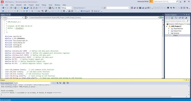
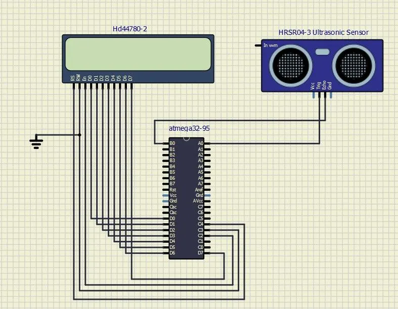
After succesfully Running the code in Atmel Studio adding the HEX file of project into ATMEGA 328 IC of our created simulation model in Simulide.
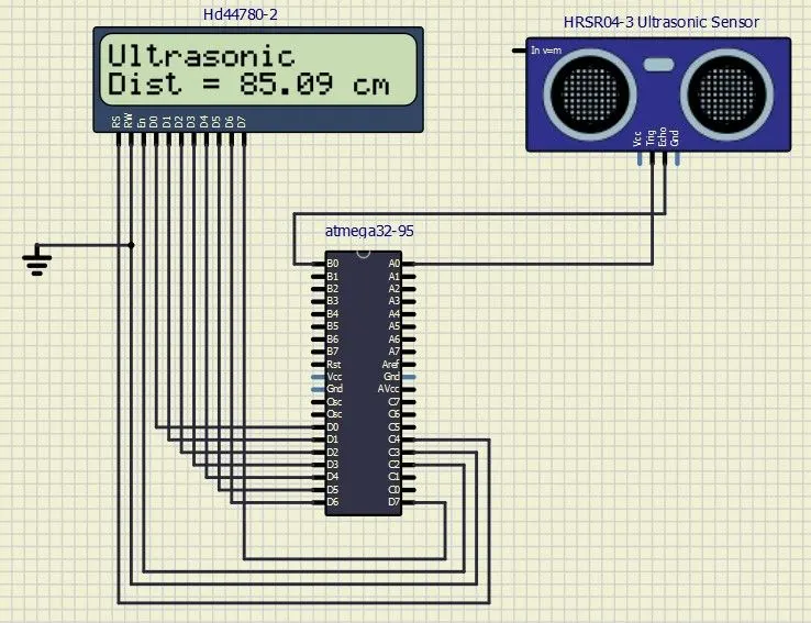
Simulation Output Result :
Input Pulse : High
Time Delay : 10 us
Distance Measured : 85.09 cm
Reference :