Project 2 - Measuring distance of an object using ultrasonic sensor (HC-SR04)
Aim: To implement a distance measuring system with atmega32 and ultrasonic sensor HC_SR04 with the use of bare metal programming.
In this project the object detection alongwith its distance measurement obtained is printed on the 16*2 LCD display. A potentiometer is used here to introduce a variable resistance which results in change in the distance measured on the LCD display.
The code for the following is :
Here individual functions are defined for each specific task. Initially, all the libraries are included.
#include <avr/io.h> //we are using the I/O registers of AVR
#define F_CPU 16000000L // define the CPU frequency
#include <util/delay.h> // delay function

#define RS_high PORTD |=(1<<0); //define bit for RS_high
#define RS_low PORTD &=~(1<<0); //define bit for RS_low
#define EN_high PORTD |= (1<<2); //define bit for EN_High
#define EN_low PORTD &=~(1<<2); //define bit for EN_Low
#define RW_high PORTD |= (1<<1);
#define RW_low PORTD &= ~(1<<1);

#define US_ERROR -1 // check ultrasonic sensor is working or not
#define US_NO_OBSTACLE -2

#define US_PORT PORTC // connect the Ultrasonic sensor on port C (2 pins)
#define US_PIN PINC // initialize the pin resistor
#define US_DDR DDRC // set the direction of data flow input or output
#define US_TRIG_POS PC0 // the trigger pin connected to port C0
#define US_ECHO_POS PC1 // echo pin connected to port C1

int distance, previous_distance;
Here the RS_HIGH bit is defined as PORTD 0th bit. Similarly RS_LOW bit is defined as PORTD &=~(1<<0) which means the PORTD should act like a input for 0th bit for the RS_LOW command. EN_HIGH is defined as second bit, EN_LOW command is defined for second bit as input. Finally RW_HIGH and RW_LOW is defined for bit 1 of PORTD.
US_ERROR -1 and US_NO_OBSTACLE -2 is used to check working condition and availaibility of object in the range of the sensor. Ultrasonic sensor is connected to PORTC. Then PULL-UP resistor is initialised followed by setting the direction of data flow input or output.
US_TRIG_POS PC0 is the command used to trigger pin connected to port C0. Similarly US_ECHO_POS PC1 is used to define the echo pin connected to port C1. Special variables distance and previous_distance are declared as global variables.
Next is the LCD command function:
void lcd_cmd(unsigned char cmd) //lcd_command function
{
	PORTB= cmd;
	RS_low;
	RW_high;
	EN_high;
	_delay_ms(1);
	EN_low;
}
In this function whatever values were defined in the previous preprocessor directives for RS_LOW,RW_HIGH,EN_HIGH and EN_LOW are called. Always there should be delay of at least 1ms between EN_HIGH and EN_LOW commands are called. cmd is an unsigned char datatype variable and the value of cmd is stored in PORTB.
lcd_data sub-function:
void lcd_data(unsigned char data) //data function

{
	PORTB= data;
	RW_low;
	RS_high;
	EN_high;
	_delay_ms(1);
	EN_low;

}
The function lcd_data has a void datatype with an argument of datatype unsigned char, the variable name is data. Again port B is selected as the address for the values present in the variable data. RW_LOW command is called followed by RS_HIGH and EN_HIGH delay of 1ms is provided finally EN_LOW is called which completes the function definition.
The lcd_init sub-function:
void lcd_init() //initialization

{

	RW_high;
	RS_high;

	EN_high;

	PORTB = 0xff; //make lcd data portB direction as output

	lcd_cmd(0x38);_delay_ms(5); //16x2 lcd 8 bit
	lcd_cmd(0x02);_delay_ms(5); //
	lcd_cmd(0x01);_delay_ms(5); //clear command
	lcd_cmd(0x0c);_delay_ms(5); //display on, cursor off
	lcd_cmd(0x06);_delay_ms(5); //auto increment
	lcd_cmd(0x80);_delay_ms(5); // 8th line, 0th position
}
First RW command is high then register select is high followed by enable high. PORTB is declared as OUTPUT because the hex value is 0xff. The LCD initialization is done by passing the pre-defined command codes with a constant delay for each command.
- 0x38 is for 2 lines and a 5*7 matrix.
- 0x02 is for the return home command.
- 0x01 is for clear screen command.
- 0x0c is for the display on cursor off command.
- 0x06 is for increment cursor
- 0x80 is for FORCE cursor on begin on first line.
The cursorpos sub-function:
void cursorpos(char x,char y) //Cursor position
{
	if((x<1 || x>2)||(y<1 || y>16)) //condition will checks the 2 rows and 16 columns
	{
		x=1;
		y=1;
	}
	if (x==1)
	{
		lcd_cmd(0x7F+y); //{ 80-1 = 7F} for starting the 1st line hex decimal value (80)(7f+y to start from that column)
	}
	else
	{
		lcd_cmd(0xBF+y); //{0C-1 = 0B} for starting the 2nd line, 2nd row
	}
}
This function is used to define the cursor position on the lcd. In the first condition the if condition for number of rows and columns is initialized, the rows should be from 1 or 2 and the column numbers should be from 1 to 16. For first row and first column lcd_cmd is 0X7F+y , the command for starting the 2nd line 2nd row is lcd_cmd(0XBF+y).
The lcd_out sub-function:
void lcd_out(char a, char b,char *str) //lcd out function, checking position we want to print

{
	cursorpos(a,b);
	while(*str)
	{
		lcd_data(*str);
		str++;
	}
}
This function is used for checking the position we need to print on the lcd. The condition is while loop for the value of *str pointer. It will be reiterated till the condition is true. The sub function lcd_data is called with the value of string pointer str* and the value of str should be post incremented.
The lcd_clear sub-function:
void lcd_clear()
{
	lcd_cmd (0x01); // clear the LCD screen
	_delay_ms(2); // waits for two milliseconds
	lcd_cmd (0x80); // this line sets the cursor to the row 1 column 1

}
void lcd_clear is the sub-function set especially for clearing the screen after each consecutive operation of object detection.
lcd_cmd is initialized for the code 0x01 and 0x80. The first command is for clearing the lcd screen and second command is for setting the cursor position to row1 and column 1 after clearing.
Now the initialization of ultrasonic sensor is needed.
void HCSR04Init()
{
	// setting the trigger pin as output as it will generate ultrasonic sound wave
	US_DDR|=(1<<US_TRIG_POS);
}
The US_DDR|=(1<<US_TRIG_POS) is the command used for setting the trigger pin as output because this pin generates the ultrasonic wave.
Now the generation of utrasonic sound of 15us is needed which is done by the HCSR04Trigger sub-function.
void HCSR04Trigger()

{ // this function will generate ultrasonic sound wave for 15 microseconds
	//Send a 10uS pulse on trigger line
	US_PORT|=(1<<US_TRIG_POS); //high
	_delay_us(15); //wait 15uS
	US_PORT&=~(1<<US_TRIG_POS); //low
}
This function basically turns on and turns off the wave of ultrasonic sound. First it is set to high and next it is set to low.
Now the pulse width modulation is needed to be defined:
uint16_t GetPulseWidth()
{
	// measure the pulse duration ,When the ultra sound echo back after hitting an object
	// read the pulse using the echo pin of the ultrasonic sensor connected to it

	uint32_t i,result;
	// check the echo pin for a certain amount of time ,if there is no signal it means the sensor is not working or not connect properly
	for(i=0;i<600000;i++)

	{
		if(!(US_PIN & (1<<US_ECHO_POS)))
		continue; //Line is still low, so wait
		else
		break; //High edge detected, so break.
	}

	if(i==600000)
	return US_ERROR; //Indicates time out
	//Setup Timer1
	TCCR1A=0X00;
	TCCR1B=(1<<CS11); // set the resolution of the timer Maximum of how much value it should count
	TCNT1=0x00; // start the counter

	for(i=0;i<600000;i++) // the 600000 value is used randomly to denote a very small amount of time, almost 40 milliseconds
	{
		if(US_PIN & (1<<US_ECHO_POS))
		{
			if(TCNT1 > 60000) break; else continue; // if the TCNT1 value gets higher than 60000 it means there is not object in the range of the sensor
		}
		else
		break;
	}

	if(i==600000)
	return US_NO_OBSTACLE; //Indicates time out
	//Falling edge found
	result=TCNT1; //store value of the counted pulse time in the TCNT1 register
	//Stop Timer
	TCCR1B=0x00;

	if(result > 60000)
	return US_NO_OBSTACLE; //No obstacle
	else
	return (result>>1);
}
Here the key points to consider are
- Timer name
- Timer channel
- Timer mode
Two if conditions are implemented which are nested in a FOR loop of limits 0 - 600000us. In the first if condition the line is low the sensor will continue to generate the sound wave else it will break because the line is already high. If i is exactly equal to 600000us then the error message should be displayed. Next the timer 1 is to be set. It has two channels A and B. Channel A is set to 0 and channel B is used to set the resolution of the timer as to which bit it needs to measure. The register TCNT1 is used to store the counter value. Again a for loop is implemented for checking the timeout. This is done by checking the value stored in counter TCNT1 with the compared value (600000u). The result so far obtained is stored in the variable result or displayed based on the pre-defined value US_NO_OBSTACLE.
Next, the main function is implemented:
int main(void)

{
	lcd_init(); // initializing LCD
	char numberString[4]; // we are defining an array of character to store integer to be displayed on the LCD screen

	while(1)

	{
		uint16_t r;
		_delay_ms(100); //Let the LCD Module start
		//Set io port direction of sensor
		HCSR04Init();
		while(1)
		{
			//Send a trigger pulse
			HCSR04Trigger(); // calling the ultrasonic sound wave generator function
			//Measure the width of pulse
			r=GetPulseWidth(); // duration of the ultrasound
			//Handle Errors
			if(r==US_ERROR) //send US_ERROR variable to -1 if no pulse

			{
				cursorpos(1, 1); //lcd_setCursor(column, row)
				char j[10] = "Error!";
				lcd_out(1,1,&j);
			}
			else
			{
				distance=(r*0.034/2.0); // distance in centimeters
				char f[15]= "Distance = ";
				lcd_out(1,0,&f);
				itoa(distance, numberString, 10); // distance is an integer number, this line converts integer into array of character
				lcd_out(2,4,numberString);
				char h[6] = " cm";
				lcd_out(2,10,&h);
				previous_distance= distance;
				_delay_ms(30);
			}
		}
	}
}
In the main function all the pre defined sub-functions are invoked. First the lcd is initialized using the lcd_init sub-function. The array named numberString is declared of size 4 and datatype is char. Next an infinite while loop is implemented:
The HCSR04 f trigger function is called followed by calling the pulse width modulation function. Then an if condition is cheked for US_ERROR and the statements for the if condition is executed until the condition is false. In the else condition the distance alongwith "Distance string" is printed. The calculation of the distance is calculated as r*0.034/2.0.
Hence the overall program executes the action of distance measurement and printing the value on lcd.
The output circuit for the program is as follows:
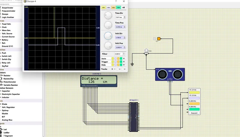
Components used:
- LCD display(16*2)
- atmega32 uc
- ultrasonic sensor (SR04)
- Oscope
Connections:
The LCD display is used in 8 bit mode so the data pins d0-d7 are connected to PINs B0-B7 because port B is declared as output device. Pins D0 is connected to RS, En is connected to D1 and RS is connected to D2. Here RW pin is not grounded because we want to write the data obtained from the sensor in real time and not print pre-defined values or statements. Output is connected to Oscope channel1 and channel2. A potentiometer is connected to output pin of SR04 to adjust the distance.
Overview of the sensor SR04:
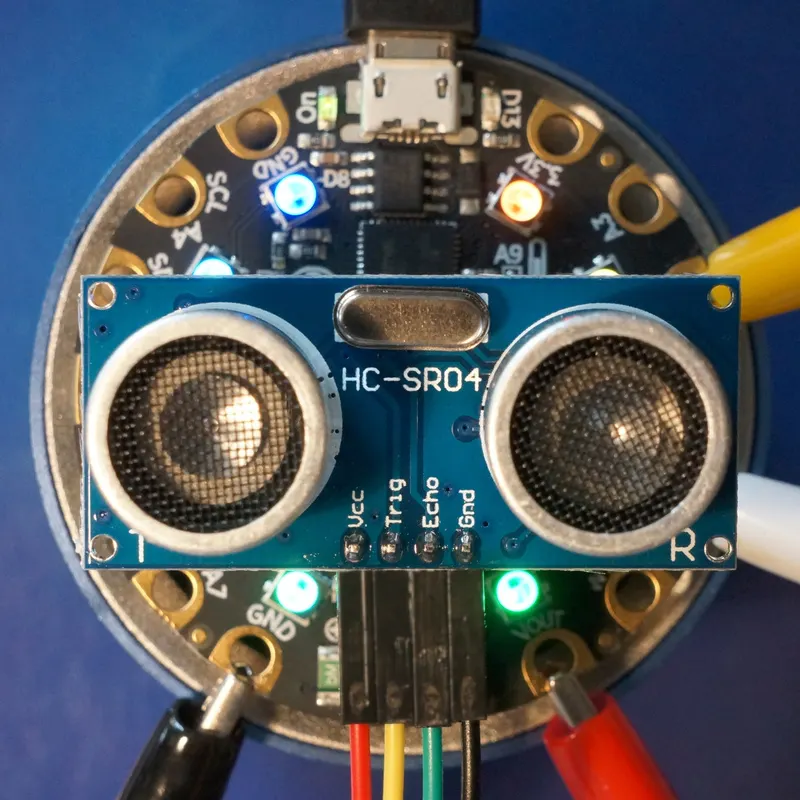
The HC-SR04 is an inexpensive distance sensor based on a pair of ultrasonic transducers with a straightforward TTL level interface and a claimed range of 2cm to 4m. Similar sensors are now commonplace with the widespread use of car parking assistance sensors.
How the HC-SR04 Ultrasonic Distance Sensor Works?
It emits an ultrasound at 40 000 Hz which travels through the air and if there is an object or obstacle on its path It will bounce back to the module. Considering the travel time and the speed of the sound you can calculate the distance.
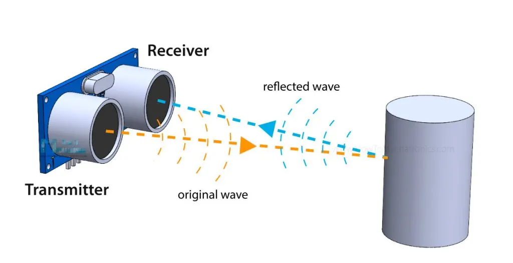
In order to generate the ultrasound we need to set the Trig pin on a High State for 10 µs. That will send out an 8 cycle ultrasonic burst which will travel at the speed of sound. The Echo pins goes high right away after that 8 cycle ultrasonic burst is sent, and it starts listening or waiting for that wave to be reflected from an object.
If there is no object or reflected pulse, the Echo pin will time-out after 38ms and get back to low state.
For that purpose we are using the following basic formula for calculating distance:
Distance = Speed x Time
We actually know both the speed and the time values. The time is the amount of time the Echo pin was HIGH, and the speed is the speed of sound which is 340m/s. There’s one additional step we need to do, and that’s divide the end result by 2. and that’s because we are measuring the duration the sound wave needs to travel to the object and bounce back.
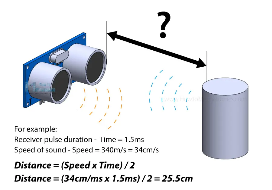
Let’s say the Echo pin was HIGH for 2ms. If we want the get the distance result in cm, we can convert the speed of sound value from 340m/s to 34cm/ms.
Distance = (Speed x Time) / 2 = (34cm/ms x 1.5ms) / 2 = 25.5cm.
So, if the Echo pin was HIGH for 2ms (which we measure using the pulseIn() function), the distance from the sensor to the object is 34cm.