Project 2-Highway Assistant-Lane Changing Assistant
PROJECT 2: HIGHWAY ASSISTANT - LANE CHANGING ASSISTANT
Aim:
Implementing the Highway Assistant Lane changing assiatant by understanding the given requiremnts.
Objective:
- Model must be developed in MATLAB Simulink per MBD guidelines.
- Code Generation Profile must be AUTOSAR Coder.
- Simulink Data Dictionary must be created for the model & must be linked to the model.
- All the input & output signals must be mapped into the Autosar Editor.
- Model Advisor Report is mandatory & this will be followed by Code Generation.
Requirements:
Requirement No 1 [Highway_DisplayUnit]:
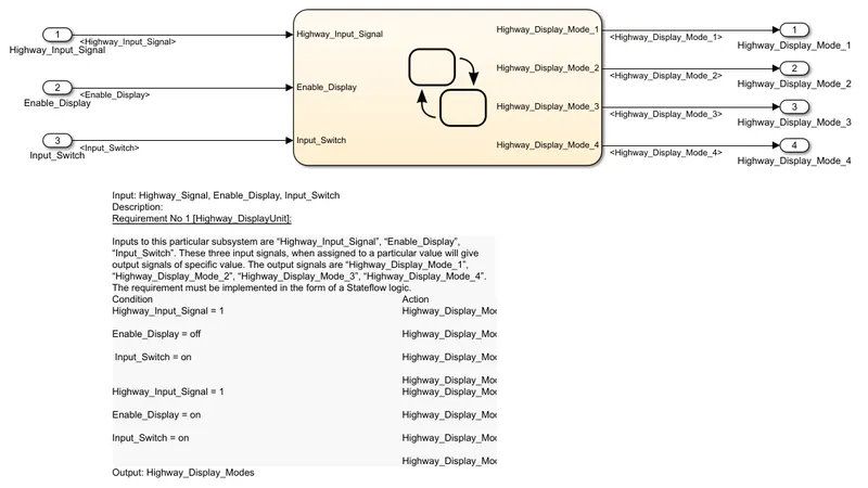
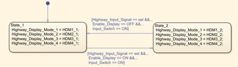
Inputs to this particular subsystem are “Highway_Input_Signal”, “Enable_Display”, “Input_Switch”. These three input signals, when assigned to a particular value will give output signals of specific value. The output signals are “Highway_Display_Mode_1”, “Highway_Display_Mode_2”, “Highway_Display_Mode_3”, “Highway_Display_Mode_4”. The requirement must be implemented in the form of a Stateflow logic.
|
Condition |
Action |
|
Highway_Input_Signal = 1 Enable_Display = off Input_Switch = on |
Highway_Display_Mode_1 = 232 Highway_Display_Mode_2 = 183 Highway_Display_Mode_3 = 41 Highway_Display_Mode_4 = 94 |
|
Highway_Input_Signal = 1 Enable_Display = on Input_Switch = on |
Highway_Display_Mode_1 = 213 Highway_Display_Mode_2 = 183 Highway_Display_Mode_3 = 9 Highway_Display_Mode_4 = 94 |
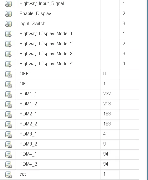
Subsystem (Highway_DisplayUnit):
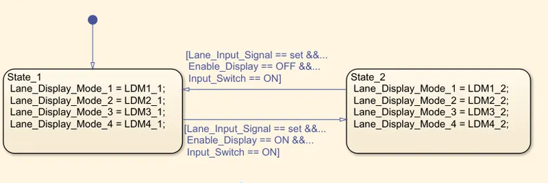
Requirement No 2 [Lane_DisplayUnit]:
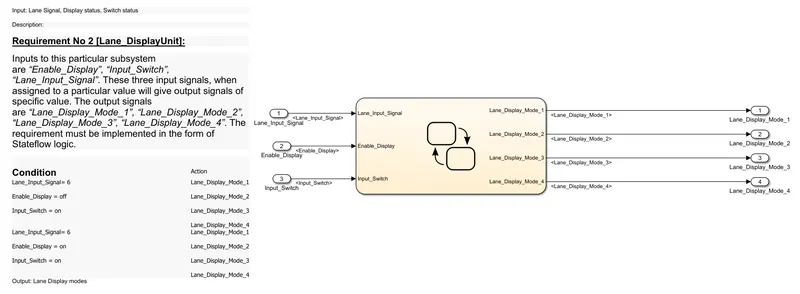
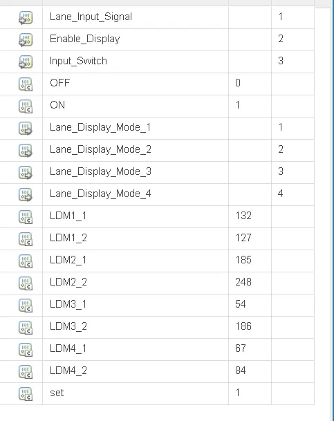
Inputs to this particular subsystem are “Enable_Display”, “Input_Switch”, “Lane_Input_Signal”. These three input signals, when assigned to a particular value will give output signals of specific value. The output signals are “Lane_Display_Mode_1”, “Lane_Display_Mode_2”, “Lane_Display_Mode_3”, “Lane_Display_Mode_4”. The requirement must be implemented in the form of Stateflow logic.
|
Condition |
Action |
|
Lane_Input_Signal= 6 Enable_Display = off Input_Switch = on |
Lane_Display_Mode_1 = 132 Lane_Display_Mode_2 = 185 Lane_Display_Mode_3 = 54 Lane_Display_Mode_4 = 67 |
|
Lane_Input_Signal= 6 Enable_Display = on Input_Switch = on |
Lane_Display_Mode_1 = 127 Lane_Display_Mode_2 = 248 Lane_Display_Mode_3 = 186 Lane_Display_Mode_4 = 84 |
Subsystem (Line_DisplayUnit)
Requirement No 3:
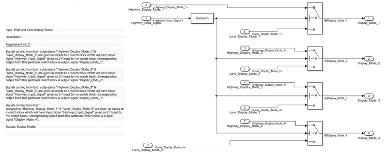
Signals coming from both subsystems “Highway_Display_Mode_1” & “Lane_Display_Mode_1” are given as inputs to a switch block which will have input signal “Highway_Input_Signal” given as 2nd input to the switch block. Corresponding output from this particular switch block is output signal “Display_Mode_1”.
Signals coming from both subsystems “Highway_Display_Mode_2” & “Lane_Display_Mode_2” are given as inputs to a switch block which will have input signal “Highway_Input_Signal” given as 2nd input to the switch block. Corresponding output from this particular switch block is output signal “Display_Mode_2”.
Signals coming from both subsystems “Highway_Display_Mode_3” & “Lane_Display_Mode_3” are given as inputs to a switch block which will have input signal “Highway_Input_Signal” given as 2nd input to the switch block. Corresponding output from this particular switch block is output signal “Display_Mode_3”.
Signals coming from both subsystems “Highway_Display_Mode_4” & “Lane_Display_Mode_4” are given as inputs to a switch block which will have input signal “Highway_Input_Signal” given as 2nd input to the switch block. Corresponding output from this particular switch block is output signal “Display_Mode_4”.
Subsystem (Requirement_3):
Combined Model:
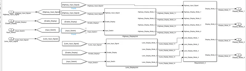
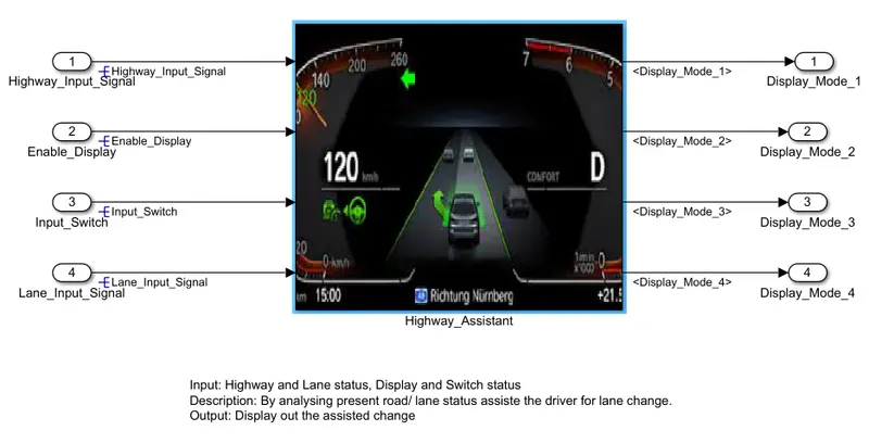
Final Model:
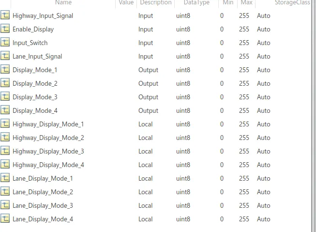
Simulink Data Dictionary:
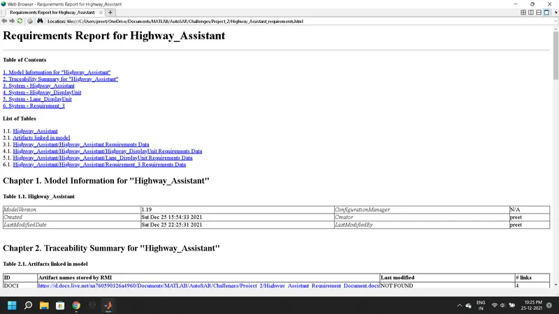
Requirement Manager Report:
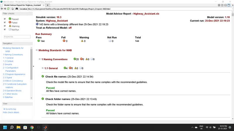
Model Advisor Report:
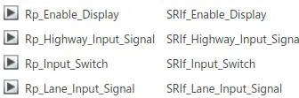
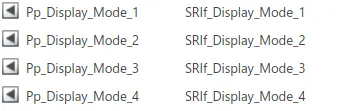
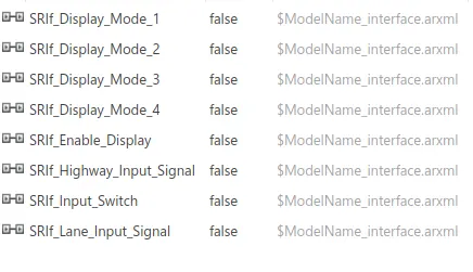
AUTOSAR Dictionary:

C Code (AUTOSAR Code Generation Report)
/*
 * File: Highway_Assistant.c
 *
 * Code generated for Simulink model 'Highway_Assistant'.
 *
 * Model version                  : 1.15
 * Simulink Coder version         : 9.5 (R2021a) 14-Nov-2020
 * C/C++ source code generated on : Sat Dec 25 18:28:33 2021
 *
 * Target selection: autosar.tlc
 * Embedded hardware selection: Intel->x86-64 (Windows64)
 * Code generation objectives:
 *    1. Execution efficiency
 *    2. RAM efficiency
 * Validation result: Not run
 */

#include "Highway_Assistant.h"

/* Named constants for Chart: '<S2>/Chart' */
#define HDM1_1                         ((uint8)232U)
#define HDM1_2                         ((uint8)213U)
#define HDM3_1                         ((uint8)41U)
#define HDM3_2                         ((uint8)9U)
#define IN_State_1                     ((uint8)1U)
#define IN_State_2                     ((uint8)2U)

/* Named constants for Chart: '<S3>/Chart' */
#define LDM1_1                         ((uint8)132U)
#define LDM1_2                         ((uint8)127U)
#define LDM2_1                         ((uint8)185U)
#define LDM2_2                         ((uint8)248U)
#define LDM3_1                         ((uint8)54U)
#define LDM3_2                         ((uint8)186U)
#define LDM4_1                         ((uint8)67U)
#define LDM4_2                         ((uint8)84U)

/* Block signals and states (default storage) */
DW rtDW;

/* Model step function */
void Highway_Assistant_Step(void)
{
  uint8 rtb_Highway_Display_Mode_1;
  uint8 rtb_Highway_Display_Mode_3;
  uint8 rtb_Lane_Display_Mode_1;
  uint8 rtb_Lane_Display_Mode_2;
  uint8 rtb_Lane_Display_Mode_3;
  uint8 rtb_Lane_Display_Mode_4;
  boolean rtb_DataTypeConversion;

  /* Chart: '<S2>/Chart' incorporates:
   *  Inport: '<Root>/Enable_Display'
   *  Inport: '<Root>/Highway_Input_Signal'
   *  Inport: '<Root>/Input_Switch'
   */
  if (rtDW.is_active_c3_Highway_Assistant == 0U) {
    rtDW.is_active_c3_Highway_Assistant = 1U;
    rtDW.is_c3_Highway_Assistant = IN_State_1;
    rtb_Highway_Display_Mode_1 = HDM1_1;
    rtb_Highway_Display_Mode_3 = HDM3_1;
  } else if (rtDW.is_c3_Highway_Assistant == IN_State_1) {
    if ((Rte_IRead_Highway_Assistant_Step_Rp_Highway_Input_Signal_DE_Highway_Input_Signal
         () == 1) &&
        (Rte_IRead_Highway_Assistant_Step_Rp_Enable_Display_DE_Enable_Display() ==
         1) && (Rte_IRead_Highway_Assistant_Step_Rp_Input_Switch_DE_Input_Switch
                () == 1)) {
      rtDW.is_c3_Highway_Assistant = IN_State_2;
      rtb_Highway_Display_Mode_1 = HDM1_2;
      rtb_Highway_Display_Mode_3 = HDM3_2;
    } else {
      rtb_Highway_Display_Mode_1 = HDM1_1;
      rtb_Highway_Display_Mode_3 = HDM3_1;
    }

    /* case IN_State_2: */