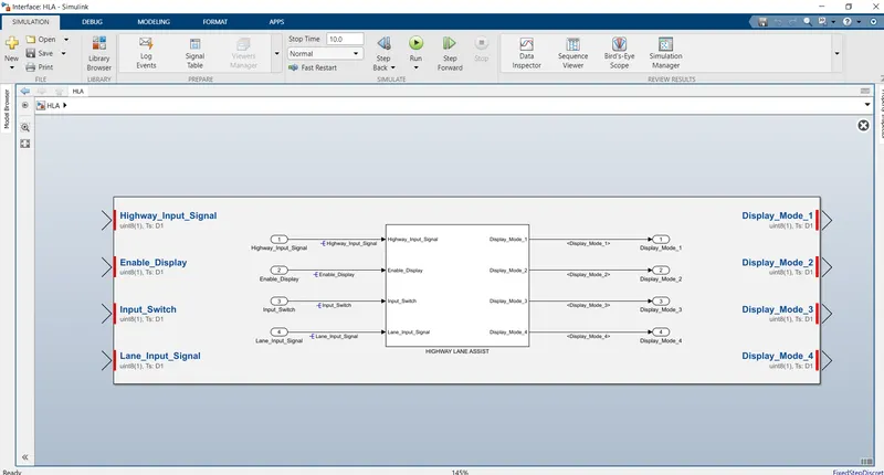
Project 2-Highway Assistant-Lane Changing Assistant
HIGHWAY ASSISTANT LANE CHANGING ASSISTANT
AIM:
To design and generate code for HIGHWAY ASSISTANT - LANE CHANGING ASSISTANT using AUTOSAR in SIMULINK MATLAB and check the Model advisor for MATLAB guidelines.
PROCEDURE:
SLDD: Simulink Data Dictionary is created for 4 inputs, 4 outputs and 8 localizable signals in which all storage classes are set to AUTO as it is AUTOSAR and for Data type it is UINT8 and Range is edited between 0 and 255.
SIMULINK MODEL:
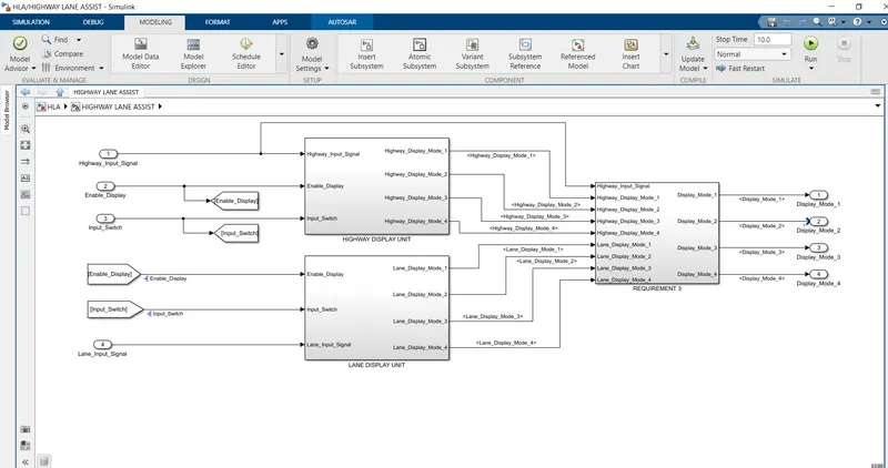
This Simulink model is created for three requirements HIGHWAY_DISPLAYUNIT, LANE_DISPLAYUNIT, and REQUIREMENT No.3
HIGHWAY_DISPLAYUNIT:
For this we use three input signals “Highway_Input_Signal”, “Enable_Display” and “Input_Switch” for a chart which has two conditions and two actions and this chart has four outputs “Highway_Display_Mode_1”, “Highway_Display_Mode_2”, “Highway_Display_Mode_3” and “Highway_Display_Mode_4.”
|
Condition |
Action |
|
Highway_Input_Signal = 1 Enable_Display = off Input_Switch = on |
Highway_Display_Mode_1 = 232 Highway_Display_Mode_2 = 183 Highway_Display_Mode_3 = 41 Highway_Display_Mode_4 = 94 |
|
Highway_Input_Signal = 1 Enable_Display = on Input_Switch = on |
Highway_Display_Mode_1 = 213 Highway_Display_Mode_2 = 183 Highway_Display_Mode_3 = 9 Highway_Display_Mode_4 = 94 |
LANE_DISPLAYUNIT:
For this we use three input signals out of which two input signals are taken from HIGHWAY_DISPLAYUNIT by means of FROM and GOTO block. The Input signals are “Enable_Display”, “Input_Switch” and “Lane_Input_Signal” for a chart which has two condition with respect to two conditions and this chart has four outputs “Lane_Display_Mode_1”, “Lane_Display_Mode_2”, “Lane_Display_Mode_3” and “Lane_Display_Mode_4.”
|
Condition |
Action |
|
Lane_Input_Signal= 6 Enable_Display = off Input_Switch = on |
Lane_Display_Mode_1 = 132 Lane_Display_Mode_2 = 185 Lane_Display_Mode_3 = 54 Lane_Display_Mode_4 = 67 |
|
Lane_Input_Signal= 6 Enable_Display = on Input_Switch = on |
Lane_Display_Mode_1 = 127 Lane_Display_Mode_2 = 248 Lane_Display_Mode_3 = 186 Lane_Display_Mode_4 = 84 |
REQUIREMENT No.3
For this we must create four switch blocks in which all second inputs of switch blocks are from “Highway_Input_Signal” and the first and third inputs of all four switch blocks are from output signals from HIGHWAY_DISPLAYUNIT, LANE_DISPLAYUNIT respectively and the output is
“Highway_Display_Mode_1” & “Lane_Display_Mode_1” - DISPLAY_MODE_1
“Highway_Display_Mode_2” & “Lane_Display_Mode_2” - DISPLAY_MODE_2
“Highway_Display_Mode_3” & “Lane_Display_Mode_3” - DISPLAY_MODE_3
“Highway_Display_Mode_4” & “Lane_Display_Mode_4” - DISPLAY_MODE_4
All three requirements are made to three separate subsystems and all three subsystems are made into a single subsystem.
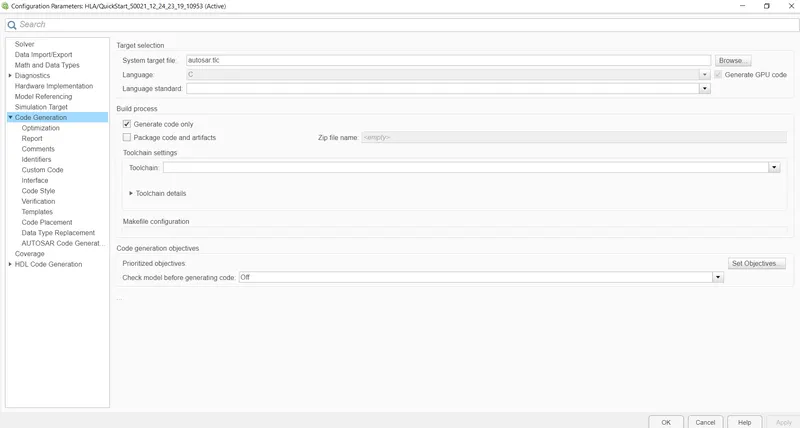
Under Model settings for Solver Configurations select FIXED STEP CONTINUOUS, and under CODE Generation settings for target location select autosar.tlc
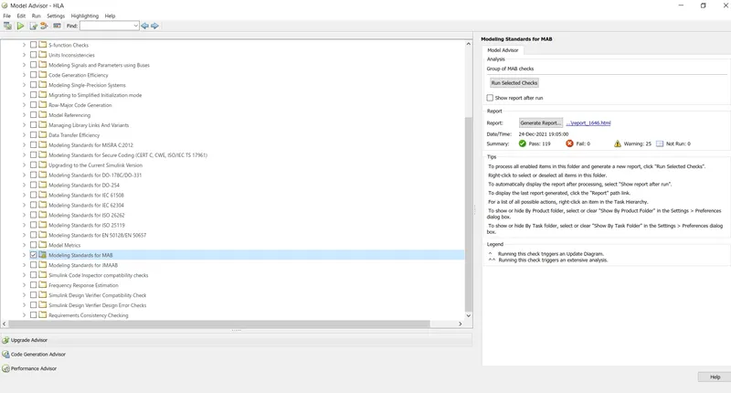
Now under modelling go for model advisor setting and check model advisor for MAB GUIDELINESS and checked for error. Run and simulate the model to check for errors.
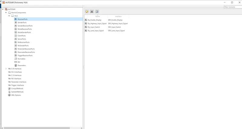
Selecting AUTOSAR COMPONENTS under APPS and click AUTOSAR SW COMPONENTS and select the AUTOSAR DICTIONARY. In this first we have edited the XML in which all packages are named and located. Then under SRif all the Input and Output signals are made with prefix (SRif_) and in subdivision of all SRif go to Data Elements and change the name with prefix (DE_). The Input signals are renamed with prefix (Rp_ ) under Rp and Output signals are renamed with prefix (Pp_). Then under runnable init and timing events are also changed.
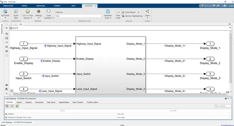
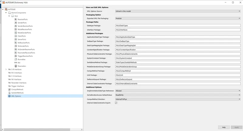
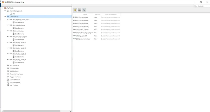
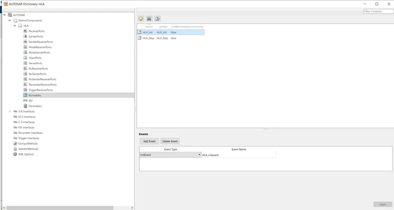
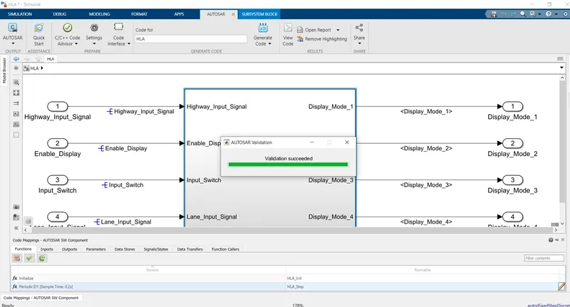
Upon closing the AUTOSAR DICTIONARY under AUTOSAR SW COMPONENT refresh autosar port map and then click tick button which will validate and check if VALIDATION IS SUCCESSFUL.
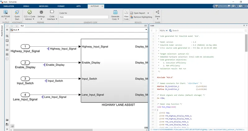
Once this is over go for Quick Start which will resolve all changes necessary in model settings automatically and generate code.
The Simulink model, SLDD file and Model Advisor report are attached as files and AUTOSAR code generated folder is attached as ZIP folder.