Project 2 Adaptive Cruise Control
ADAPTIVE CRUISE CONTROL
AIM:
To develop a MATLAB model using SIMULINK which is used to create ADAPTIVE CRUISE CONTROL for controlling the speed of the host vehicle for safety and to drive tension free in heavy traffic.
DESCRIPTION:
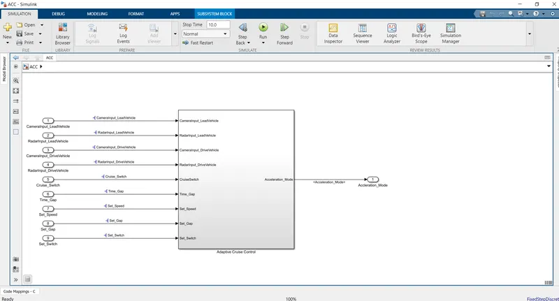
- The SLDD for the following Inputs and Outputs are created as per the challenge and saved it as ACC.sldd. Storage class for inputs is given as IMPORTEDEXTERN and for OUTPUT it is given as EXPORT TO FILE. For all signals sampling time is set as 0.01 secs.
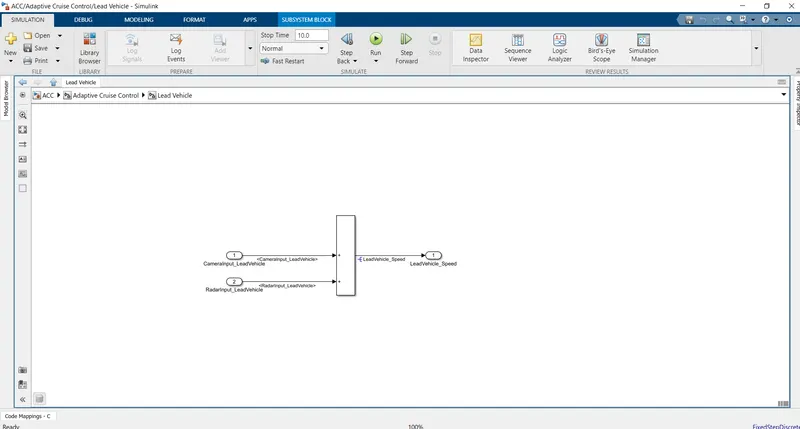
- Two INPUTS named as CameraInput_LeadVehicle & RadarInput_LeadVehicle are used and a sum block is used to sum the signals produces by these two inputs. Radar input is the core as it measures the lead vehicle distance, the result of the speed block as LeadVehicle_Speed which is critical in determining the speed of the Lead vehicle.
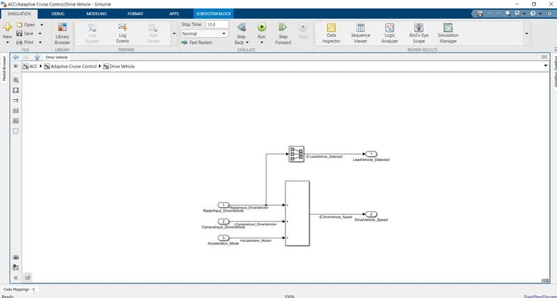
- Two more INPUTS namely CameraInput_DriveVehicle & RadarInput_DriveVehicle are created as input blocks and in addition to this one more input will be given from output Acceleration_Mode using a Unit Delay block, All three blocks are summed using sum Block and output is given as Apart from this one more output is taken which is LeadVehicle_Detected and this output is mere rename of RadarInput_DriveVehicle made using Signal Conversion Block.
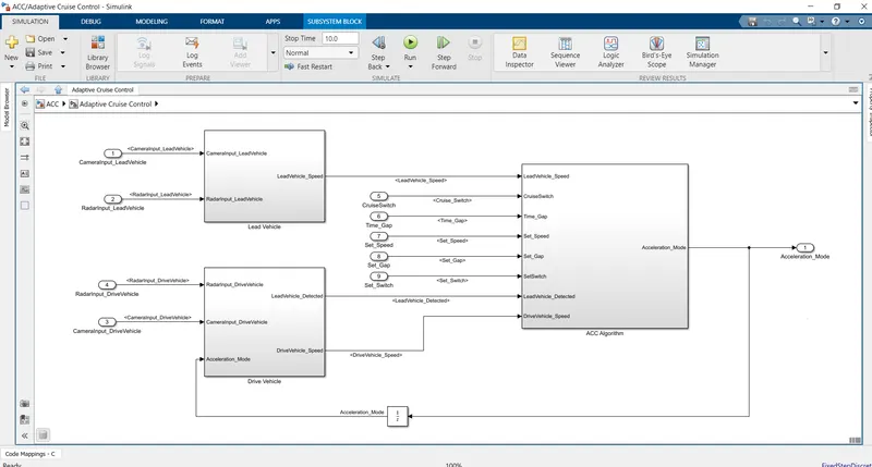
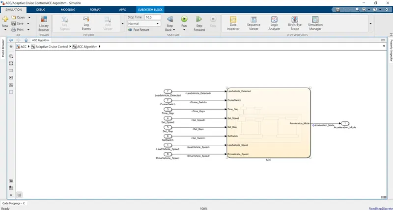
- Five more INPUTS namelyTime_Gap, Set_Speed, Set_Gap, CruiseSwitch and The outputs derived from previous two points LeadVehicle_Speed, DriveVehicle_Speed and LeadVehicle_Detected are also made as INPUTS in addition to the five INPUTS and all eight INPUTS are fed into STATE MACHINE LOGIC with a single Output that is Acceleration_Mode from which input for DriveVehicle_Speed is created.
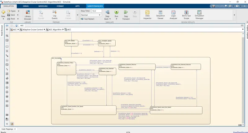
- State Machine Logic has THREE STATES for implementing various ACCELERATION MODES from 0 to 5 which will be fed into OUTPUT and three modes. The three modes are given below:
- ACC OFF MODE Acceleration_Mode is at value 0 by input signal CruiseSwitch, If CruiseSwitch is equal to 1, state ACC STANDBY mode will get activated. If CruiseSwitch is equal to 0, state ACC OFF mode will get activated, from either ACC ON mode or ACC STANDBY mode. This is the default Mode.
- ACC STANDBY MODE Acceleration_Mode is at value 1 by both input signals CruiseSwitch & SetSwitch. If CruiseSwitch is equal to 1, state ACC STANDBY mode will get activated. If CruiseSwitch is equal to 0, state ACC OFF mode will get activated, from either ACC ON mode or ACC STANDBY mode, If SetSwitch is equal to 1, state ACC ON mode will get activated. If SetSwitch is equal to 0, state ACC STANDBY mode will get activated.
- ACC ON MODE The ACC ON mode has six sub states for which the transition conditions are made as per the requirements.
- Three SUBSYSTEMS are created by selecting respective blocks, SUBSYSTEM 1 named as Lead Vehicle using all the blocks used in POINT 2, SUBSYTEM 2 named as Drive Vehicle using all the blocks used in POINT 3 and SUBSYSTEM 3 named as ADAPTICE CRUISE CONTROL ALGORITHM using the entire STATE FLOW LOGIC and again making all three SUBSYTEMS into ONE SUBSYSTEM named as ACC which leaves with EIGHT INPUT BLOCKS and ONE OUTPUT BLOCK.
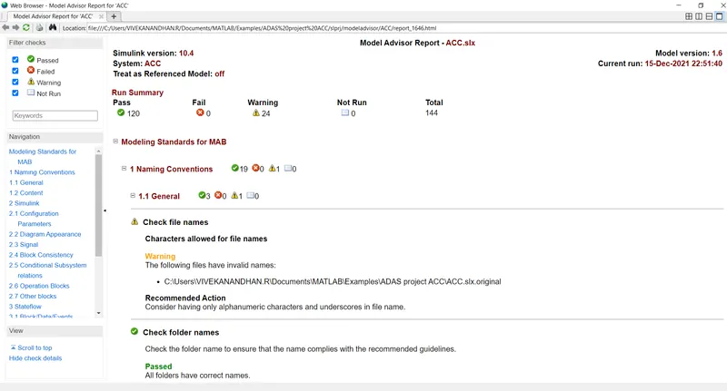
- All the signals are resolved and the MODEL ADVISOR CHECK is done for MAB guidelines and ensuring all guidelines have been passed.
- All three Subsystems are tagged for requirements using the word document attached with name as ACC.docx.
The Code generation is done by changing the CODE GENERATION settings to ert.tlc which is for EMBEDDED CODING and under CODE GENERATION SETTINGS choose INTERFACE under which we should tick “SUPPORT FLOATING NUMBERS.” Then the SUBSYSTEM is Right clicked and select CODE GENERATION and select Build S block. Since my MATLAB version isn’t supporting CODE GENERATION I haven’t created code for this project.
The SIMULINK MODEL, Traceability file, requirement word file, Model advisor report and SLDD file are attached. The screen shots are also attached for our reference.