Project 1- Traffic Jam Assistant Feature
TRAFFIC JAM ASSISTANCE FEATURE
AIM:
To develop one specific requirement of Traffic jam assistance algorithm which will feature in Instrument Panel Cluster.
MODEL and DESCRIPTION:
The Simulink Data Dictionary is created for the inputs, outputs and localizable signals and also for the Constants which has pre-defined values. Storage class for input signal is “IMPORTEDEXTERN”, for output signal it is “EXPORTTOFILE” for Calibration values it is “CONSTANT” and for localizable values it is “LOCALIZABLE.” The Range of values are entered and the Initial values for calibration signals are also entered. The SLDD file is attached.
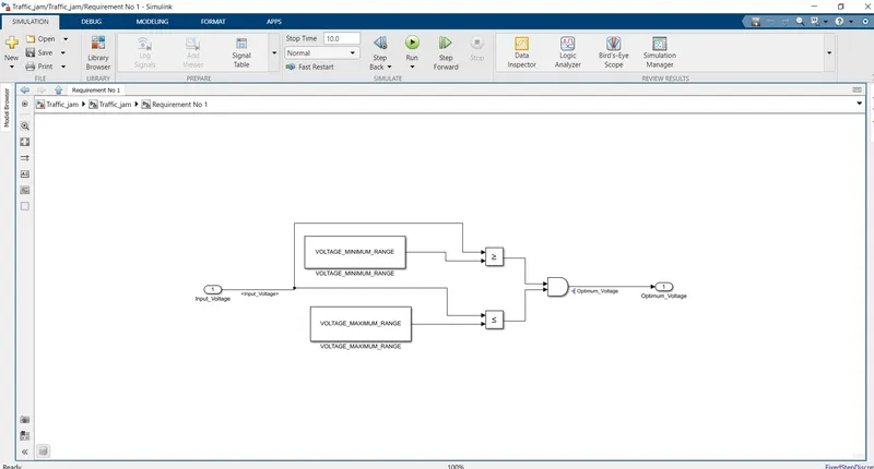
The project is divided into two requirements, where Input_Voltage is compared against pre defined voltage values like minimum and maximum voltage. Incoming input signal “Input_Voltage” must be greater than – equal to “VOLTAGE_MINIMUM_RANGE” and less than – equal to “VOLTAGE_MAXIMUM_RANGE”. The output signal for this will be “OPTIMUM_VOLTAGE.” This is considered as separate subsystem and tagged as Requirement No 1. If the input voltage must be 30 and 50 then the result will be fed to AND gate and the result will be “Optimum_Voltage”
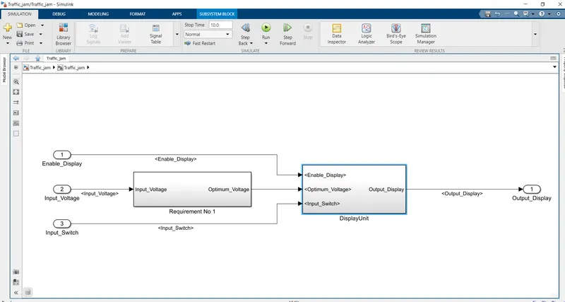
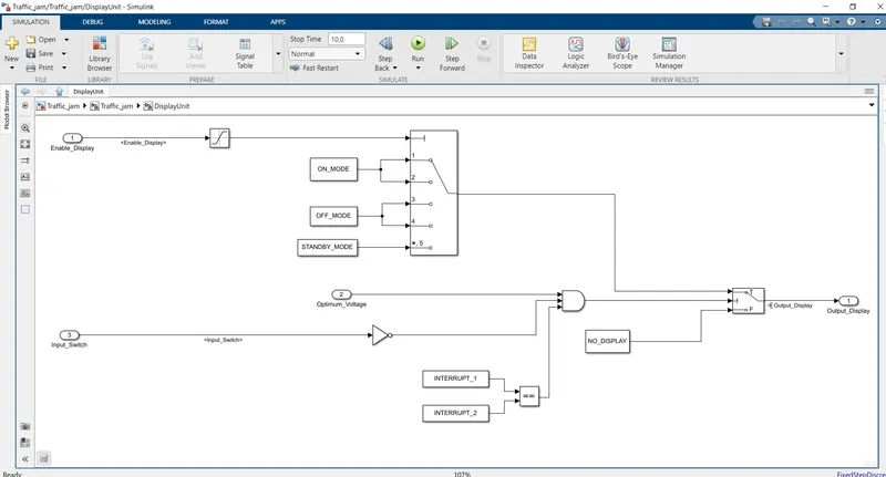
The second Requirement will be designed using three inputs, The first input being “Enable_Display” and it must be saturated between 0 and 7 and compared against pre defined constant values in Multiport switch. The multiport switch with 5 ports is created in which Port 1 and 2 is connected to “ON_MODE” while 3 and 4 is connected to “OFF_MODE” and the 5 is connected to “STANDBY_MODE.” A switch block is created and the first input of switch is connected to Multiport switch output. A constant block with value “NO_DISPLAY” is created and is connected to the third input of switch block. “Input_Switch” is created and the signal is given to NOT gate and this value is compared in AND gate with the output signal of Requirement No 1. The Calibration Signals “INTERRUPT 1” and “INTERRUPT 2” are compared using IF and if both are equal then it gives an output as 1 and this is also compared in AND gate along with NOT of “Input_Switch” and the “Optimum_Voltage” and the output of this AND is given to 2nd port of Switch block. The out of the Switch block is the Output of the entire model and it is “Output_Display.” This entire design is created as a subsystem and named as DISPLAYUNIT SUBSYSTEM.
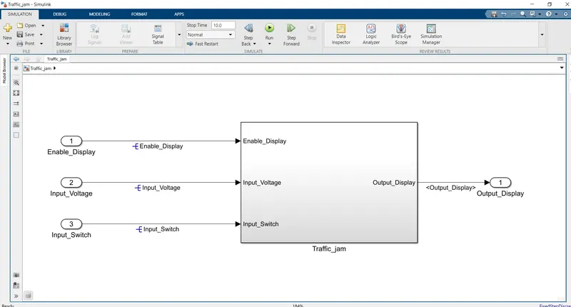
Both the subsystems are created into a subsystem with three inputs “Input_Voltage” ”Input_Switch” ”Enable_Display” and a output “Output_Display”.
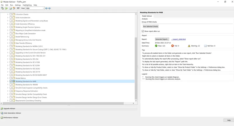
Model advisor is performed for MAB guidelines and checked for errors and the report is attached for your reference. The Image of report is also attached.
In configuration parameters for code generation selection is made for embedded coder. The final subsystem is right clicked and selection is C/C++ code and S-Function is generated SIL block is created and the SIL block File is also attached. The code generated folder is converted into ZIP folder and it is also attached.
Both the requirements are tagged and the Traceability file is also attached.