Project 2-Highway Assistant-Lane Changing Assistant
Aim:
To develop one specific requirement of Highway Assistant – Lane Changing Assistant algorithm. Idea is to familiarize with concepts of Autosar Software Component Development in MATLAB Environment by following the Model Based Development guidelines. The Project must be done keeping in mind the following processes & steps.
- This model must be developed in MATLAB Simulink per MBD guidelines.
- Code Generation Profile must be Autosar Coder.
- Simulink Data Dictionary must be created for the model & must be linked to the model.
- All the input & output signals must be mapped into the Autosar Editor.
- Model Advisor Report is mandatory & this will be followed by Code Generation.
Basic Working Principle:
Highway Assistant is a partially automated driving function for a speed range of up to 180 km/h (112 mph) on highways. It combines the RADAR-based longitudinal guidance of Adaptive Cruise Control (ACC) with the video-based lateral guidance of lane-keeping support in one system. Highway Assistant can be supplemented by an automatic lane change initiated and monitored by the driver in a speed range of 60 – 130 km/h (35 – 80 mph). The Lane Change Assistant works by using two mid-range RADAR sensors that are concealed in the rear bumper – one on the left, one on the right. These two sensors monitors the area alongside and behind the car. Powerful control software collates the sensor information to create a complete picture of all traffic in the area behind the vehicle. Whenever another vehicle approaches at speed from behind or is already present in the blind spot, a signal such as a warning light in the side mirror alerts the driver to the hazard. Should the driver still activate the turn signal with the intention of changing lanes, the system issues an additional acoustic and/or haptic warning.
Given Requirements:
Requirement No 1 [Highway_DisplayUnit]:
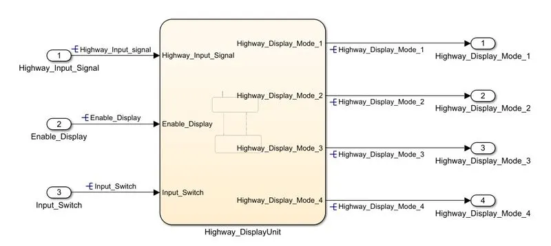
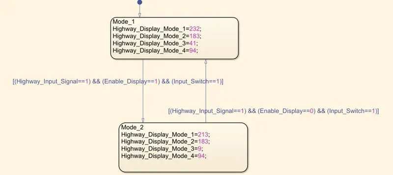
Inputs to this particular subsystem are “Highway_Input_Signal”, “Enable_Display”, “Input_Switch”. These three input signals, when assigned to a particular value will give output signals of specific value. The output signals are “Highway_Display_Mode_1”, “Highway_Display_Mode_2”, “Highway_Display_Mode_3”, “Highway_Display_Mode_4”. The requirement must be implemented in the form of a Stateflow logic.
|
Condition |
Action |
|
Highway_Input_Signal = 1 Enable_Display = off Input_Switch = on |
Highway_Display_Mode_1 = 232 Highway_Display_Mode_2 = 183 Highway_Display_Mode_3 = 41 Highway_Display_Mode_4 = 94 |
|
Highway_Input_Signal = 1 Enable_Display = on Input_Switch = on |
Highway_Display_Mode_1 = 213 Highway_Display_Mode_2 = 183 Highway_Display_Mode_3 = 9 Highway_Display_Mode_4 = 94 |
Requirement No 2 [Lane_DisplayUnit]:
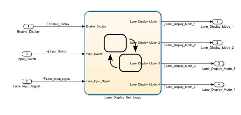
Inputs to this particular subsystem are “Enable_Display”, “Input_Switch”, “Lane_Input_Signal”. These three input signals, when assigned to a particular value will give output signals of specific value. The output signals are “Lane_Display_Mode_1”, “Lane_Display_Mode_2”, “Lane_Display_Mode_3”, “Lane_Display_Mode_4”. The requirement must be implemented in the form of Stateflow logic.
|
Condition |
Action |
|
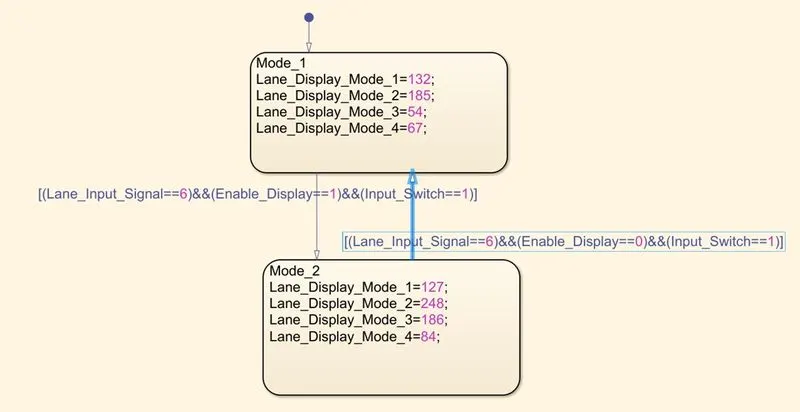
Lane_Input_Signal= 6 Enable_Display = off Input_Switch = on |
Lane_Display_Mode_1 = 132 Lane_Display_Mode_2 = 185 Lane_Display_Mode_3 = 54 Lane_Display_Mode_4 = 67 |
|
Lane_Input_Signal= 6 Enable_Display = on Input_Switch = on |
Lane_Display_Mode_1 = 127 Lane_Display_Mode_2 = 248 Lane_Display_Mode_3 = 186 Lane_Display_Mode_4 = 84 |
Requirement No 3:
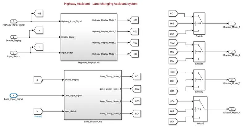
Signals coming from both subsystems “Highway_Display_Mode_1” & “Lane_Display_Mode_1” are given as inputs to a switch block which will have input signal “Highway_Input_Signal” given as 2nd input to the switch block. Corresponding output from this particular switch block is output signal “Display_Mode_1”.
Signals coming from both subsystems “Highway_Display_Mode_2” & “Lane_Display_Mode_2” are given as inputs to a switch block which will have input signal “Highway_Input_Signal” given as 2nd input to the switch block. Corresponding output from this particular switch block is output signal “Display_Mode_2”.
Signals coming from both subsystems “Highway_Display_Mode_3” & “Lane_Display_Mode_3” are given as inputs to a switch block which will have input signal “Highway_Input_Signal” given as 2nd input to the switch block. Corresponding output from this particular switch block is output signal “Display_Mode_3”.
Signals coming from both subsystems “Highway_Display_Mode_4” & “Lane_Display_Mode_4” are given as inputs to a switch block which will have input signal “Highway_Input_Signal” given as 2nd input to the switch block. Corresponding output from this particular switch block is output signal “Display_Mode_4”.
Description of Algorithm Development Steps:
Step1: Open the MATLAB - new blank simulink mopdel.
Step2: In the main model add two subsystems for requirement1 and requirement2 to be fulfilled and add 4 switch blocks for requirement3 fulfillment.
Step3:For requirement1 as per given data ,3 input signals are needed so 3 inports are used and 4 local signals are produced as outputs for that 4 goto blocks are employed. we mean it as local because they join with the output of requirement2 subsystem andd gets processed by third requirement system to give final actual outputs.
Step4: For Requirement2 3 input signals and 4 local output signals are used for that 3 inports and 4 goto blocks are picked from library. Two inputs are same for requiremnet1 and 2 so they can be merged using goto and from blocks or simply taken in general.
Step5:Requirement3 states that first local input from requirement1 system and first local input from requirement2 block are used as input fro 1st switch block along with Highway_Input_Signal which is general input.
Step6: Similarly this is followed fopr remaining three switch blocks.Highway_Input_Signal is the middle signal for all 4 switch blocks.
Step7: 4 outports are connected at the output side of switch blocks for taking main outputs.
Step8: The subsystem are developed inside requirement1 system named as Highway_DisplayUnit for writing the condition for transitions.
Step9: Similarly requirement2 is named as Lane_DisplayUnit and inside it also subsystems are developed for writing the condition for transitions using charts.
Step10: Finally all the connections are given and signals are labelled and resolved.
Step11:Save the model and open Model explorer and new ----- data dictionary option is selected.
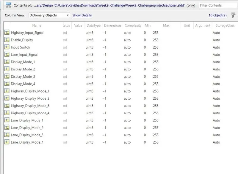
Step12: Add signals and rename and change the datatype, range and other details.
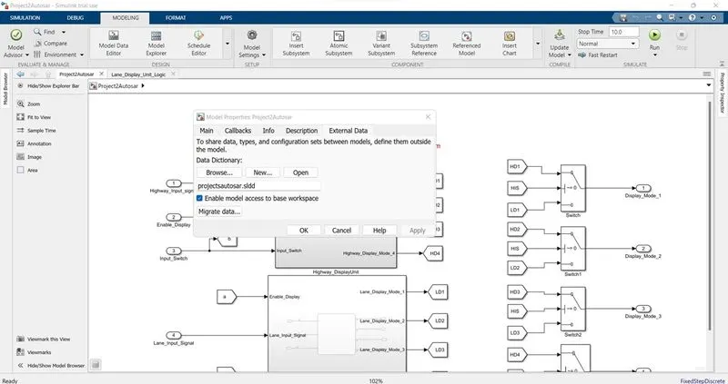
Step13: Save it as project2autosar.sldd file and open link to data dictionary and select the path adn file name and click ok for linking the sldd with the model.
Step14: Now save and run the model
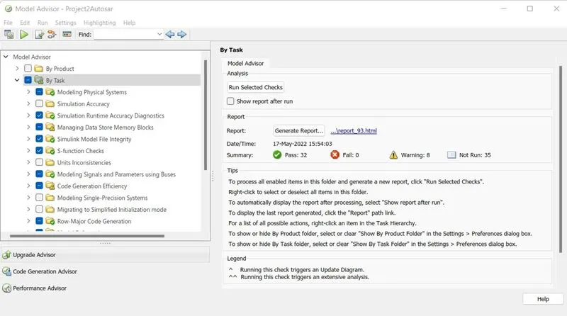
Step15: Now open model advisor and select the project file name and select the necessary checks to be run. Finally click on run the check option.
Step16: Model advisor results will be displayed after run and u can generate and save the report.
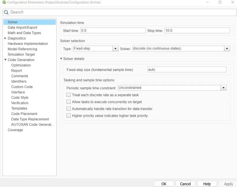
Step17: Open the configuration parameter settings and make the following changes:
solver- fixed, discontinuous
Code generation: system Target file as : Autosar.tlc
If you want coverage go for that setting else apply and click ok
Step18:Open Autosar Component tool box and at the bottom left corner you will find code mapping - Autosar Sw components. click on that to open it.
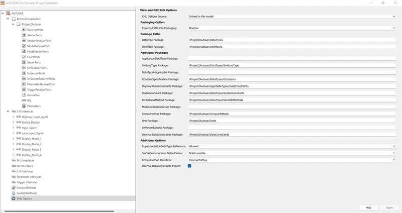
Step19:Click on the config Autosar Dictionary and select XML option and type the necesssary fields as shown in the following image and apply it.
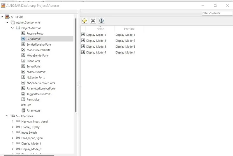
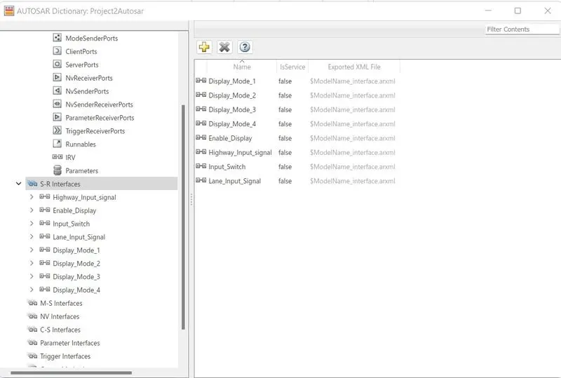
Step20:Then goto SR interfaces and name the local interfacing signals, similarly open receiver ports & sender ports and do the + addition of i/p and o/p signal and mapping of corresponding interfaces is also done.
[If sldd is properly linked and called this manual mapping is not needed, its automatically loaded]
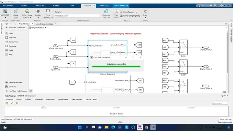
Step21: Then click on the validation icon and once its done we shall go for code generation.
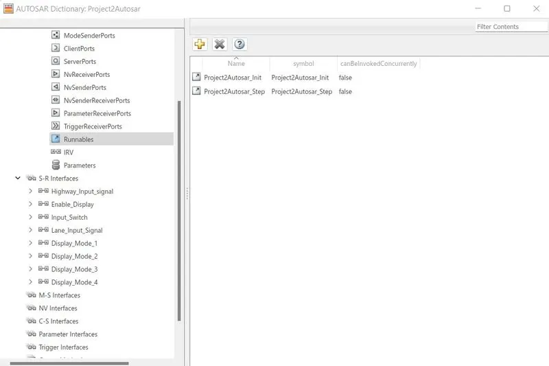
Step22:Under Runnables you can find the init and step files created
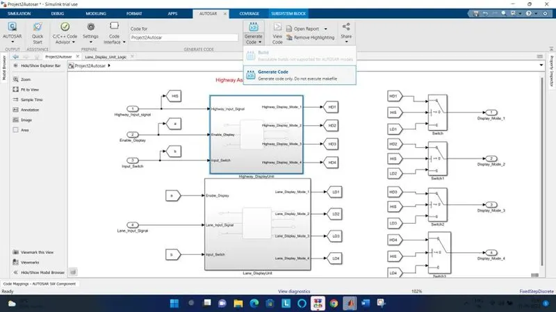
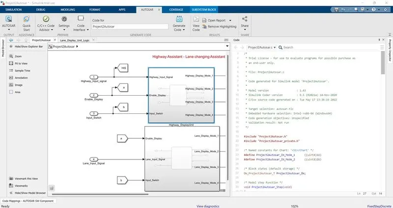
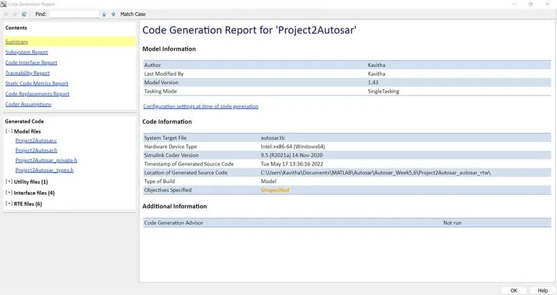
Step23:Click on genertae the code option and in few minutes we will get our code displayed in the right side. We can click on open report and save the document as pdf for reference.
Simulink Model Generated:
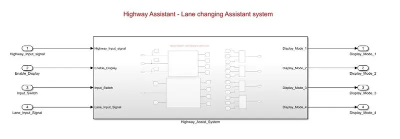
Main model overview:
Inner subsystems showing three main requirements:
Requirement1 subsystem -
Stateflow chart inside the requirement1 subsystem showing transitions and Actions.
Subsystem inside mainmodel fro requirement2
Stateflow chart inside the requirement2 subsystem showing transitions and Actions.
Results & Outputs:
SLDD file created in model explorer
Linking of sldd with the model is shown below:
Selecting the project model for running model advisor check
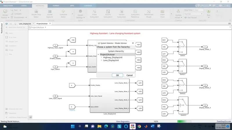
Model advisor check is inititaed by selecting the checks and clicking the Run selected checks button
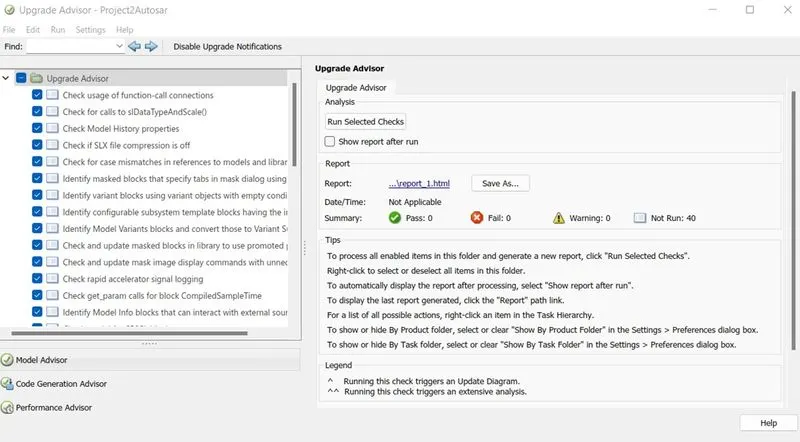
Model advisor report sample
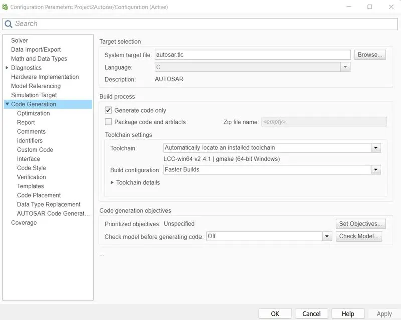
Configuration parameter settings for Autosar component generation
System target file is selected asAutosar.tlc
Solver is set to fixed and discontinuous.
Now open Autosar component toolbox and @ bottom left corner we can see code mappings-AUTOSAR SW Component
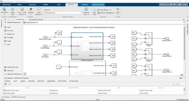
code mappings-AUTOSAR SW Component window showing inports

code mappings-AUTOSAR SW Component window showing outports

Config Autosar Dictionary - XML option settings are made & applied
We can see the auto mapped sender ports, receiver ports and s-r interfaces in the following images else do it by adding and mapping to corresponding interface signal.
Receiver ports:
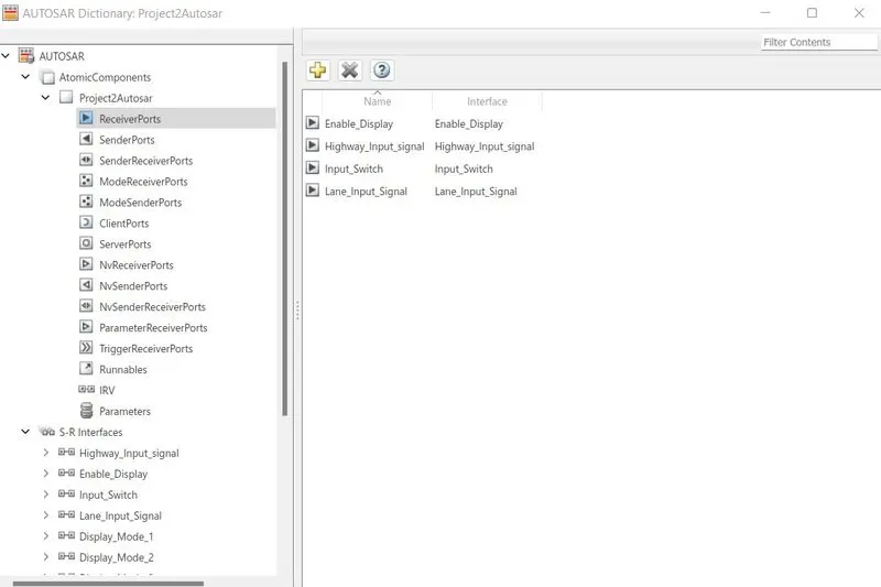
Sender ports:
S-R Interfaces
Autosar component file is validated successfully.
Runnable files - init & step can be seen as below
In order to generate the code click on generate code ooption as shown below
YOu can find the auto generated code @ the right side.
Sample of code generation report summary
Conclusion:
Thus the Highway Lane assist feature is implemented in the AUTOSAR compliance and code has been generated after simulink modelling, sldd linking adn advisor check respectively.