Project 1- Traffic Jam Assistant Feature
Project 1- Traffic Jam Assistant Feature
AIM:
To develop simulink model for one of the main ADAS features “ Traffic Jam Assistance '' algorithm. Only a part of the whole traffic jam assistance algorithm is implemented here due to complexity in handling the whole system. After the model development as per MBD guidelines, Simulink data dictionary(SLDD) is created and linked to the model and Model Advisor checks are done as per MAAB guidelines and then generate a Model advisor report. Finally, code generation is to be done and the report have to be attached.
Procedural Description of the project:
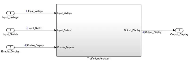
Step1: Open MATLAB - new blank simulink model - for main traffic jam assistant feature take a main subsystem block and take 3 inports for taking the inputs.
The input signals are named as Input_Voltage, Input_Switch, Enable_Display and take one outport for main output whose signal name is Output_Display.
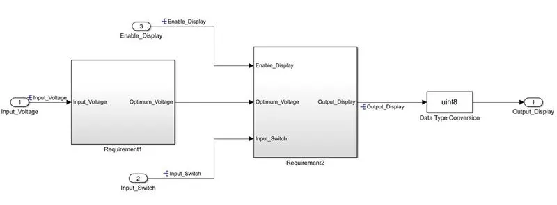
Step2:Inside the main system two subsystems are created one satisfying given requuirement 1 and another subsystem satisfying requirements2.
Requirements1 and 2 are given as below:
Requirement No 1:
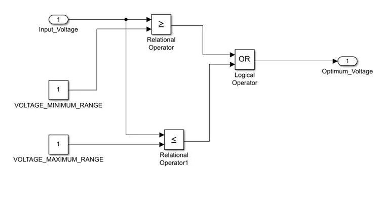
- Input Signal “Input_Voltage” is compared against voltage values “VOLTAGE_MINIMUM_RANGE” & “VOLTAGE_MAXIMUM_RANGE”.
- Incoming input signal “Input_Voltage” must be greater than – equal to “VOLTAGE_MINIMUM_RANGE” and less than – equal to “VOLTAGE_MAXIMUM_RANGE”.
- Output signal from here is “Optimum_Voltage” which will be one of the inputs to the subsystem “DisplayUnit”.
Requirement No 2 (DisplayUnit Subsystem):
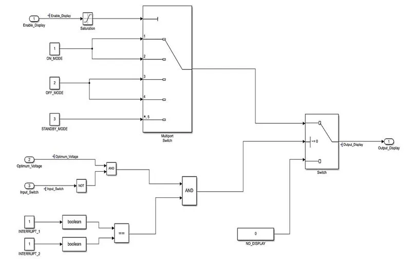
- Input Signals are “Optimum_Voltage”, “Input_Switch”,“Enable_Display”. Signal “Enable_Display” must be saturated between the range 0 – 7. Output signal from the subsystem is “Output_Display”.
- Input Signal “Enable_Display” is compared against pre – defined set of values in a multiport switch. Total data ports in the multiport switch is 5.
- Multiport switch inputs 1 & 2 is connected to calibration signal “ON_MODE”, Multiport switch inputs 3 & 4 is connected to calibration signal “OFF_MODE” while Multiport switch input 5 is connected to calibration signal “STANDBY_MODE”.
- The output from Multiport switch is connected to the first input port of the Switch block. The third input port of the Switch block is connected to the calibration signal “NO_DISPLAY”.
- Meanwhile NOT value of input signal “Input_Switch” is compared in an AND gate against input signal “Optimum_Voltage” and the output from comparing if calibration signals “INTERRUPT_1” & “INTERRUPT_2” are equal. The output of the AND gate is the second input of the switch block.
- The output from the switch block is “Output_Display”.
Step3: Inside Requirement1 subsystem Input_Voltage is compared against VOLTAGE_MINIMUM_RANGE using first relational operator[Greater than or equal to] and Input_Voltage is compared against VOLTAGE_MAXIMUM_RANGE using second relational operator[Less than or equal to].
Step4: Output from both the relational operators are compared and ORed to take decision using OR logical block and output is given to the port as Optimum_Voltage signal.
Step5: Inside requirement subsystem 2, one multiport switch is used to compare and switch to any one of the case:
Enable_Display is connected to saturated to lower value:0 and higher value:7, then ON_MODE is connected to 1 and 2 pins of multiport switch.
OFF_MODE is connected to 3 and 4 pins of multiport switch. STANDBY_MODE is connected to 5th pin.
Output from multiport switch is given as first input for switch block2.
step6: Optimum_Voltage and Inverted output of Input_Switch are ANDed and INTERRUPTS1and2 are compared against == and both the first AND output and relational output are connected to second AND and output of AND is given as 2nd input for switch2.
Step7: The third input of switch block is connected to calibration constant NO_DISPLAY.
Step8:The output from the switch block is “Output_Display” given to outport.
Step9:This output is given as input to data conversion unit and taken as main output of Traffic jam assist system.
Step10: Provide all signal names in each level and do necessary resolving of signals.
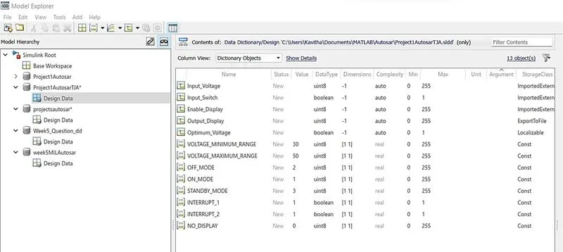
Step11: Save the model and open model explorer and click new data dictionary and save it as project1.sldd
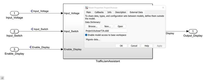
Step12: Data dictionary is created for 3 input, 1 output, 1 local and 8 constant signals and using link to data dictionary option its linked with the model.
Step13: Now run the model along wiith sldd and check for any errors or major warnings..
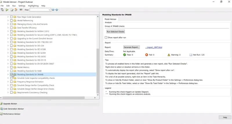
Step14: Open model advisor and select the project name and click on the checks you need to perform and run the selected checks.
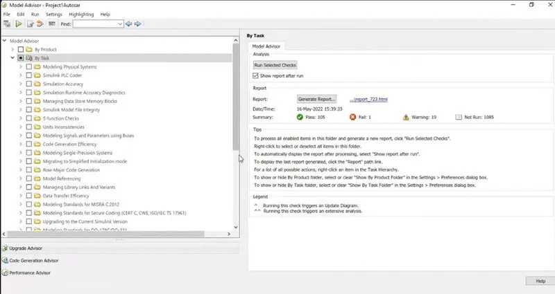
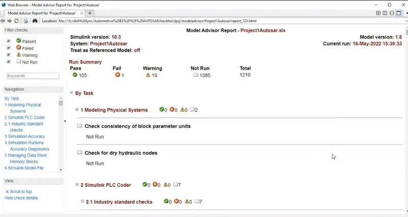
Step15: After sometime the model advisor check is performed and it displays no of checks passed, failed and shows warnings.
Step16: Generate the model advisor report and save oit as pdf
Step17: Now open configurations parameter settings and make solver settings to fixeed step size of 0.01
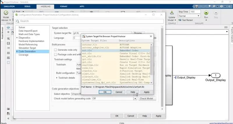
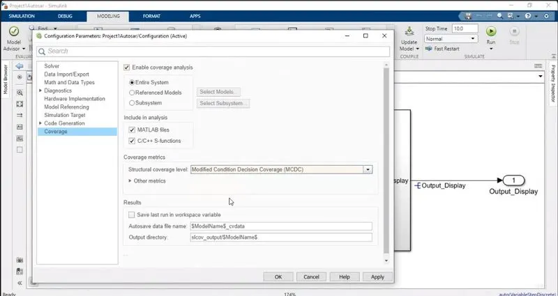
Step18: Under code generation change your target coder name as ert.tlc/anyother and enable code generation. also in coverage settings if you want enable coverage access and select MCDC.
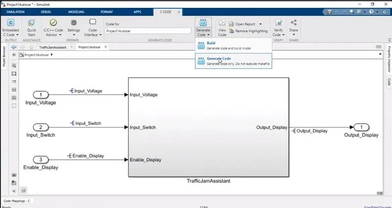
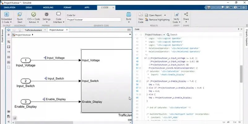
Step19: Goto Ccode app and under generate code select build or select generate code option.
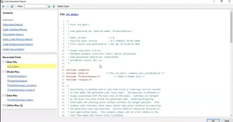
Step 20:Your code will be shown after its generated on the right side windoe and even you can oopen code using tool pallet and save the report.
Simulink model:
This is the main model of traffic jam assist system
SUBSYSTEMS showing Requirement1 and 2 fulfillment
Requirement 1 subsystem @ level2
Requirement2 subsystem @level2
DATA Dictionary file created using model explorer in simulink
Results and Outputs:
The following images shows various results and procedures followed while obtaining the same.
Linking of sldd with the model
Running of model advisor check: selecting of JMAAB checks
Model advisor results are shown below:
Model advisor report sample
Configuration parameter settings done before code generation
Solver settings are made for fixed step size of 0.01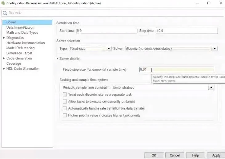
Under code generation system target file is choosen as ert.tlc.
This image below shows generation of code for the model
If you do coverage settings you can even get coverage analysis done as shown below:
Code generated succesfully and displayed as seen below
Sample code generated report
Conclusion:
Thus the part of Traffic Jam Assist system is modelled successfully using simulink and sldd linking , model advisor reports and code generation part are implemented.