Project 2 Adaptive Cruise Control
Aim of the Project:
To Develop an Adaptive Cruise Control model algorithm as per the Requirement Document given using MATLAB Simulink. Also I have to follow all the MBD related processes for the developed model like: Requirement Tagging & Traceability, SLDD creation, Configuration Parameter changes, Model Advisor check & finally do Code Generation.
Description of the project:
Step1: Open MATLAB - new blank simulink model - save it under the name Project2ACCMBD.slx
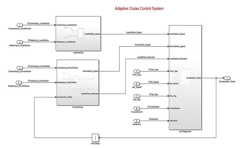
Step2:There are three main systems in this project for ACC.
1. Lead vehicle unit
2.Drive Vehicle unit
3. Main ACC Algorithm unit
So create three main subsystem blocks in main model and with 9 inports and 1 outport and i delay elemnet for providing feedback.
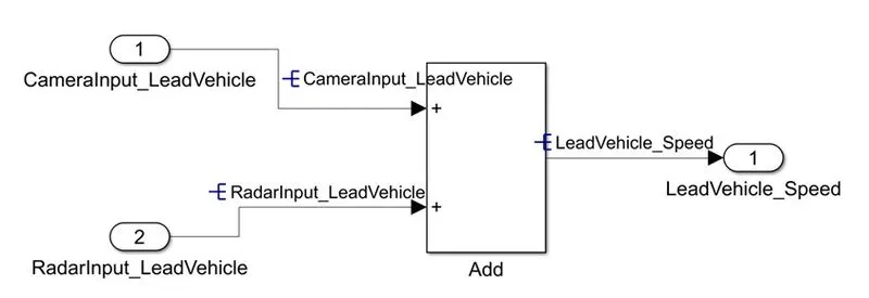
Step3: Inside subsystem1 according to "Requirement 1– Lead Vehicle" provided create two inputs and name them as
CameraInput_LeadVehicle & RadarInput_LeadVehicle.
Step4: Now take an add block and add the above two input signals and & the corresponding output is read as Speed profile output (Signal Name: LeadVehicle_Speed).
Note:Lead Vehicle is a vehicle which is driving in the road ahead of our drive vehicle.Speed data of the lead vehicle is critical in implementing the Adaptive Cruise Control algorithm.
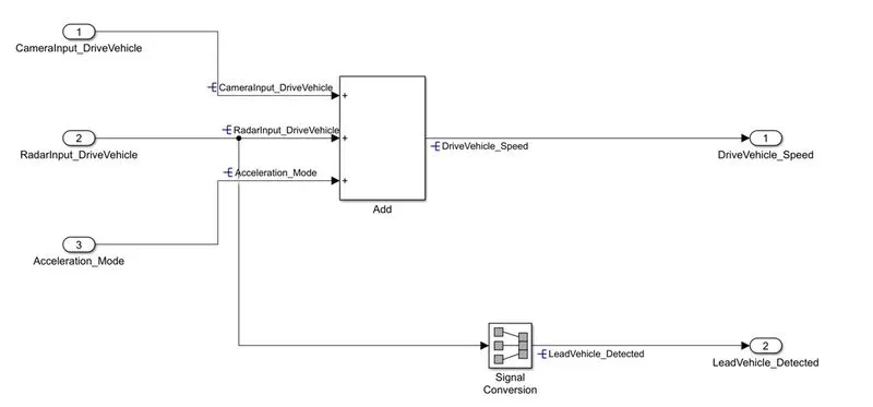
Step5: Inside subsystem2 according to "Requirement 2 – Drive Vehicle" provided create 2 input signals - CameraInput_DriveVehicle, RadarInput_DriveVehicle and third input coming from subsystem3 as feedback named Acceleration_Mode. Two outports are taken as two output signals come from this subsystem (Signal Name: DriveVehicle_Speed & LeadVehicle_Detected).
Step6: Signal DriveVehicle_Speed is summation of three input signals mentioned above & LeadVehicle_Detected is renamed from Input Signal RadarInput_DriveVehicle by mere use of Signal Conversion block.
Note:Drive Vehicle is the vehicle driven by the user & this is the vehicle which has ACC algorithm in it.
Step7: As per "Requirement 3 – Adaptive Cruise Control Algorithm" there are 5 input signals to this state machine system : Time_Gap, Set_Speed, Set_Gap, CruiseSwitch, SetSwitch.
- Also, the output signals (Signal Name: DriveVehicle_Speed & LeadVehicle_Detected) from requirement-2 is fed back as an input signal into this state machine block.
- Additionally, output signal (Signal Name: LeadVehicle_Speed) from requirement-1 is given as an input signal to this state machine block as well.
Step8: Output from this subsystem is a signal (Signal Name: Acceleration_Mode) which governs the vehicular speed of the drive vehicle which automatically adjusts its speed & velocity to match the lead vehicle.
Note: Adaptive Cruise Control feature has 3 major modes of operation: OFF Mode, STANDBY Mode & ON Mode. This particular requirement has to be implemented as state machine logic in Simulink.
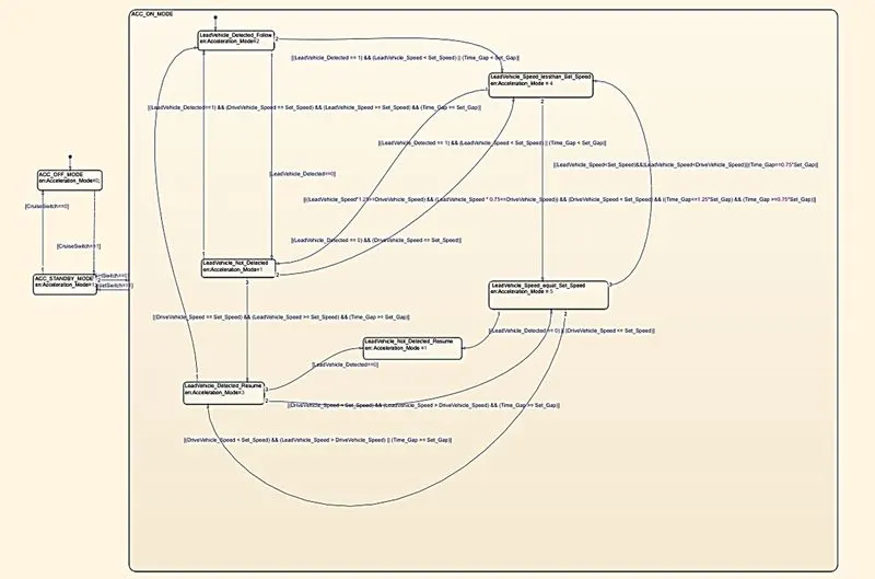
Step9: State machine Logic is implemented using 8 states. 1. OFF 2. STANDBY 3. ON
Step10: AS per the requirements there are 6 states inside 3rd state i.e.ACC ON MODE state. So these below requirements are followed to provide connection between all these states transitions & condition actions.
Requirement 3a – ACC OFF MODE state logic:
- This is the default state inside state machine logic. Output signal Acceleration_Mode is at value 0 in this state.
- This state is governed by input signal CruiseSwitch.
- If CruiseSwitch is equal to 1, state ACC STANDBY mode will get activated. If CruiseSwitch is equal to 0, state ACC OFF mode will get activated, from either ACC ON mode or ACC STANDBY mode
Requirement 3b – ACC STANDBY MODE state logic:
- This is the second activated state inside state machine logic. Output signal Acceleration_Mode is at value 1 in this state.
- This state is governed by both input signals CruiseSwitch & SetSwitch.
- If CruiseSwitch is equal to 1, state ACC STANDBY mode will get activated. If CruiseSwitch is equal to 0, state ACC OFF mode will get activated, from either ACC ON mode or ACC STANDBY mode
- If SetSwitch is equal to 1, state ACC ON mode will get activated. If SetSwitch is equal to 0, state ACC STANDBY mode will get activated.
Requirement 3c – ACC ON MODE state logic:
This state will be activated when input signal SetSwitch is equal to 1. There are 6 sub states to this state logic: They are:
- LeadVehicle_Detected_Follow (Default)
- LeadVehicle_Not_Detected
- LeadVehicle_Detected_Resume
- LeadVehicle_Not_Detected_Resume
- LeadVehicle_Speed_lessthan_Set_Speed
- LeadVehicle_Speed_equal_Set_Speed
Requirement 3c (i) – LeadVehicle_Detected_Follow (ACC ON MODE):
- This is the default sub state inside ACC ON MODE state. Output signal Acceleration_Mode is equal to 2.
- Condition to transit from LeadVehicle_Detected_Follow to LeadVehicle_Not_Detected; Input signal condition LeadVehicle_Detected == 0.
- Condition to transit from LeadVehicle_Detected_Follow to LeadVehicle_Speed_lessthan_Set_Speed; Input Signals condition (LeadVehicle_Detected == 1) && (LeadVehicle_Speed < Set_Speed) || (Time_Gap < Set_Gap).
Requirement 3c (ii) – LeadVehicle_Not_Detected (ACC ON MODE):
- Output signal Acceleration_Mode is equal to 1.
- Condition to transit from LeadVehicle_Not_Detected to LeadVehicle_Detected_Follow; Input signals condition [(LeadVehicle_Detected==1) && (DriveVehicle_Speed == Set_Speed) && (LeadVehicle_Speed >= Set_Speed) && (Time_Gap >= Set_Gap)]
- Condition to transit from LeadVehicle_Not_Detected to LeadVehicle_Speed_lessthan_Set_Speed; Input signals condition [(LeadVehicle_Detected == 1) && (LeadVehicle_Speed < Set_Speed) || (Time_Gap < Set_Gap)]
Requirement 3c (iii) – LeadVehicle_Detected_Resume (ACC ON MODE):
- Output signal Acceleration_Mode is equal to 3.
- Condition to transit from LeadVehicle_Detected_Resume to LeadVehicle_Detected_Follow; Input signals condition [(DriveVehicle_Speed == Set_Speed) && (LeadVehicle_Speed >= Set_Speed) && (Time_Gap >= Set_Gap)]
- Condition to transit from LeadVehicle_Detected_Resume to LeadVehicle_Not_Detected_Resume; Input signal condition LeadVehicle_Detected==0.
- Condition to transit from LeadVehicle_Detected_Resume to LeadVehicle_Speed_equal_Set_Speed; Input Signal condition [(DriveVehicle_Speed < Set_Speed) && (LeadVehicle_Speed > DriveVehicle_Speed) && (Time_Gap >= Set_Gap)]
Requirement 3c (iv) - LeadVehicle_Not_Detected_Resume (ACC ON MODE):
- Output signal Acceleration_Mode is equal to 1.
Requirement 3c (v) - LeadVehicle_Speed_lessthan_Set_Speed (ACC ON MODE):
- Output signal Acceleration_Mode is equal to 4.
- Condition to transit from LeadVehicle_Speed_lessthan_Set_Speed to LeadVehicle_Not_Detected; Input signal condition [(LeadVehicle_Detected == 0) && (DriveVehicle_Speed == Set_Speed)]
- Condition to transit from LeadVehicle_Speed_lessthan_Set_Speed to LeadVehicle_Speed_equal_Set_Speed; Input signals condition [((LeadVehicle_Speed*1.25>=DriveVehicle_Speed) && (LeadVehicle_Speed * 0.75<=DriveVehicle_Speed)) && (DriveVehicle_Speed < Set_Speed) && ((Time_Gap<=1.25*Set_Gap) && (Time_Gap >=0.75*Set_Gap))]
Requirement 3c (vi) - LeadVehicle_Speed_equal_Set_Speed (ACC ON MODE):
- Output signal Acceleration_Mode is equal to 5.
- Condition to transit from LeadVehicle_Speed_equal_Set_Speed to LeadVehicle_Not_Detected_Resume; Input signal conditions is [(LeadVehicle_Detected == 0) || (DriveVehicle_Speed <= Set_Speed)]
- Condition to transit from LeadVehicle_Speed_equal_Set_Speed to LeadVehicle_Detected_Resume; Input signal conditions [(DriveVehicle_Speed < Set_Speed) && (LeadVehicle_Speed > DriveVehicle_Speed) || (Time_Gap >= Set_Gap)]
- Condition to transit from LeadVehicle_Speed_equal_Set_Speed to LeadVehicle_Speed_lessthan_Set_Speed; Input signals conditions [(LeadVehicle_Speed)].
Step 11: Now provide signal ttransitions and connections inside every subsystem and main system and make signal reolve and labels.
Step12: Create SLDD file as per the table given and save it as Project2ACCMBD.sldd using model explorer - new - datadesign option
Step13: Link your SLDD with model and run it to find any errors or warnings.
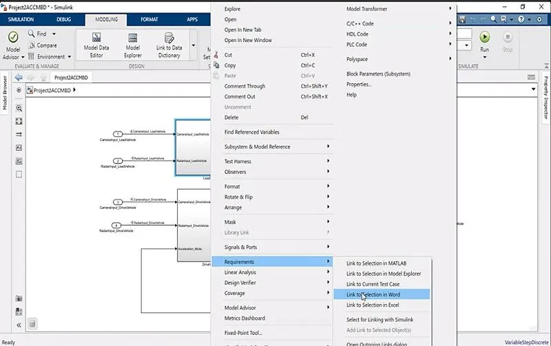
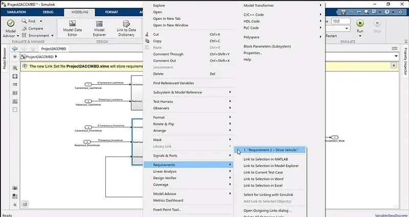
Step14:keep your word requirement file ready and select requirement1 and inside requirement1 block model right click and select requirement and select the word file appropriately.
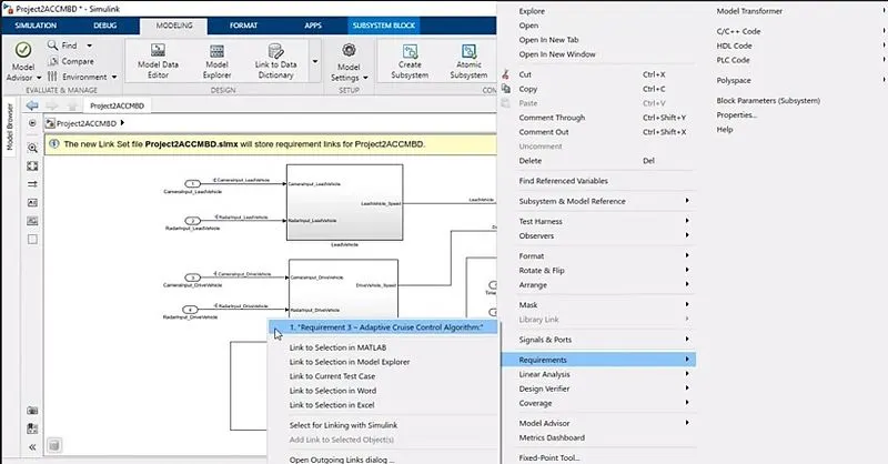
step15:Similarly add requirement2 and 3 inside each corresponding blocks
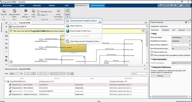
Step16: Goto Requirement editor and under share / link find generate model traceabillity reoort and click on it to have traceability part done.
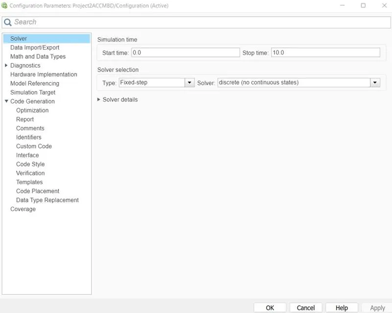
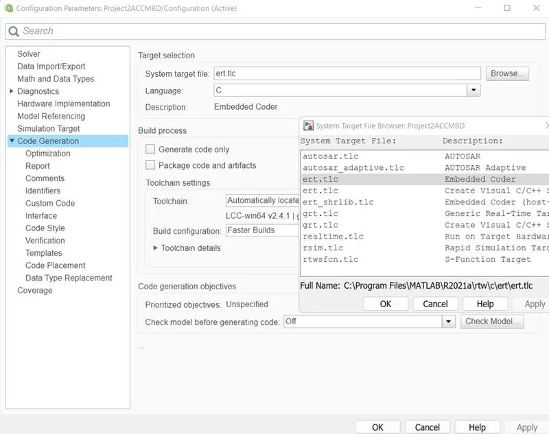
Step17: Goto configuration parameter setting and check solver settings and change target option under code generation to erc.tlc file.
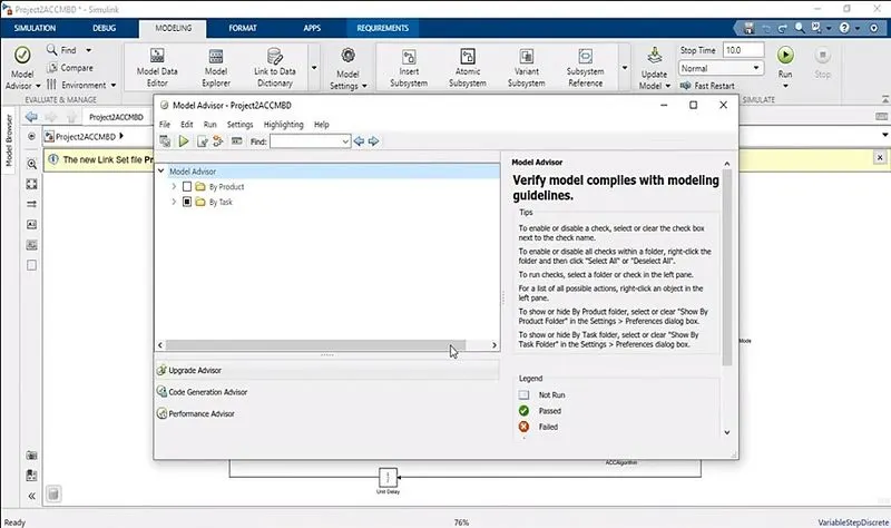
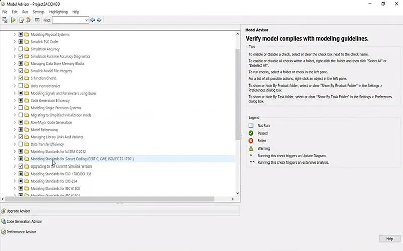
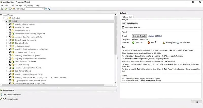
Step18:Goto model advisor, select the project name and select the checks which you want to run and clicl on run check option. You will get a command "pass and fail summary ' and generate report option. click on it to view your model advisor report.
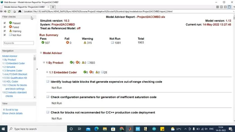
Note: this report willl give every details pertaining to test rules passed , failed and warnings
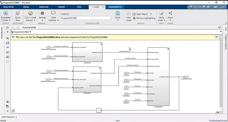
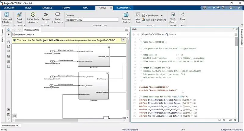
Step19:Goto C Code and select embeddd coder and run build option - generate c code. After sometime your c code will oopen up and in the tool pallette you select open report to view .c file and .h file - all will get opened up.
Step20: Now save all your reports and if you have any errors , modify and rereun the above steps.
Simulation models:
This is the main system having three major subssystems in it.
Simulink model of subsystem1:
Simulink model of subsystem2:
Simulink model of subsystem3
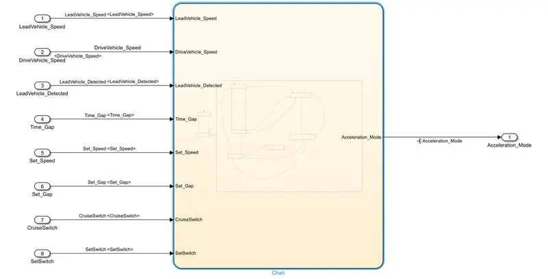
Simulink model of inner subsystem of subssystem3- stateflow chart:
Simulink Data Dictionary created:
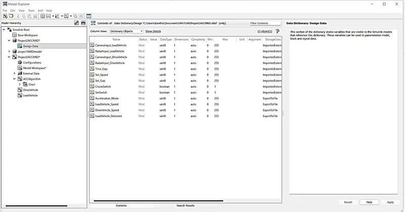
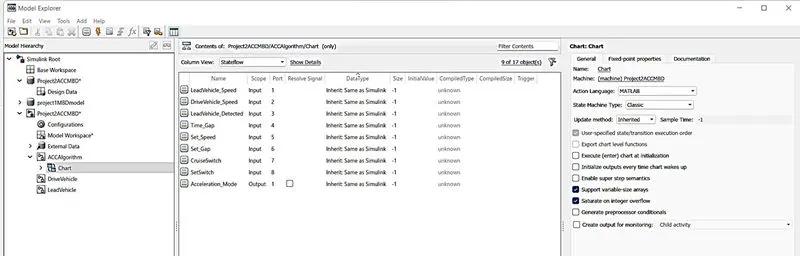
Chart models data values:
Configuratiion parameter settings modifications as per requirements:
1. In solver part
2.In Code generation
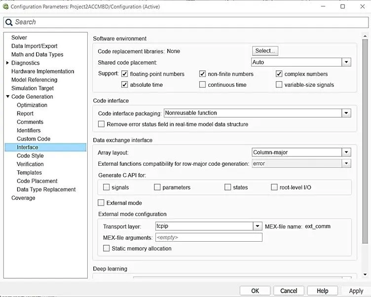
3. In Interfaces under code generation part enables support floating numbers
Requirement tagging is done by keeping the word document open: Sample of one subsystem tagging is given here
Results Obtained:
1.Requirement tagging part
Requirement tagging has been done for all subsystems and on right click we can find the linked word file name as shown below for all 3 requirements:
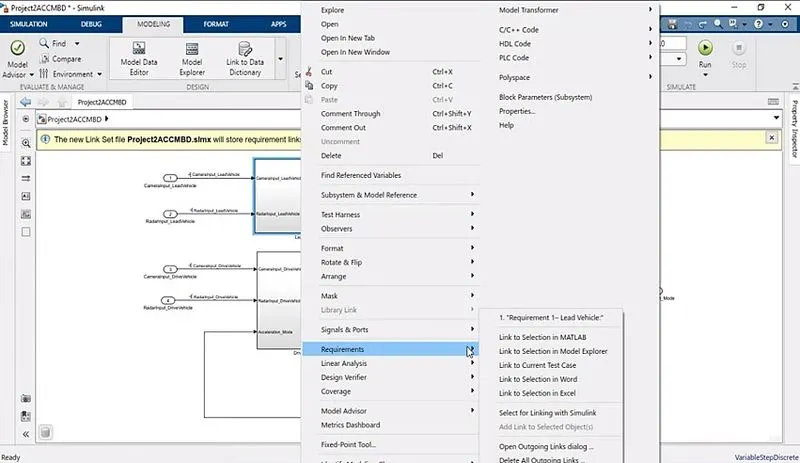
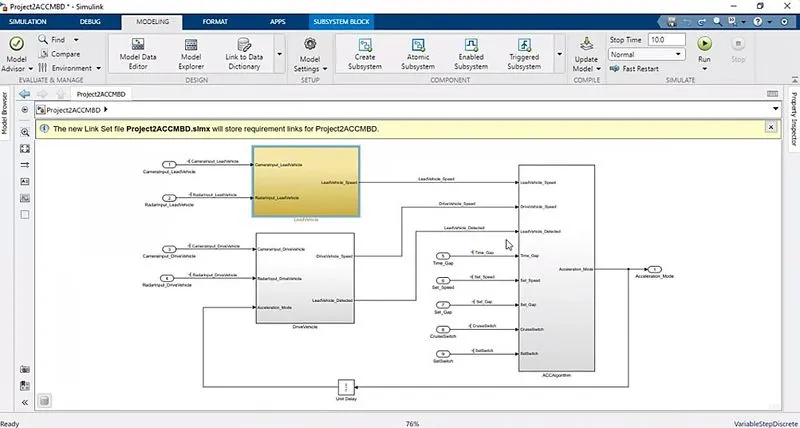
After requirement tagging is done block color changes to yellow as shown below:
2. Outputs for requirement traceability
Generating option under requirement editor is shown below
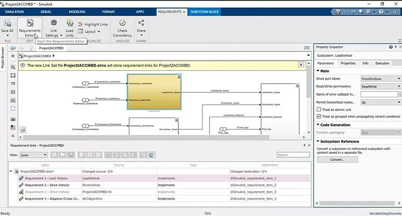
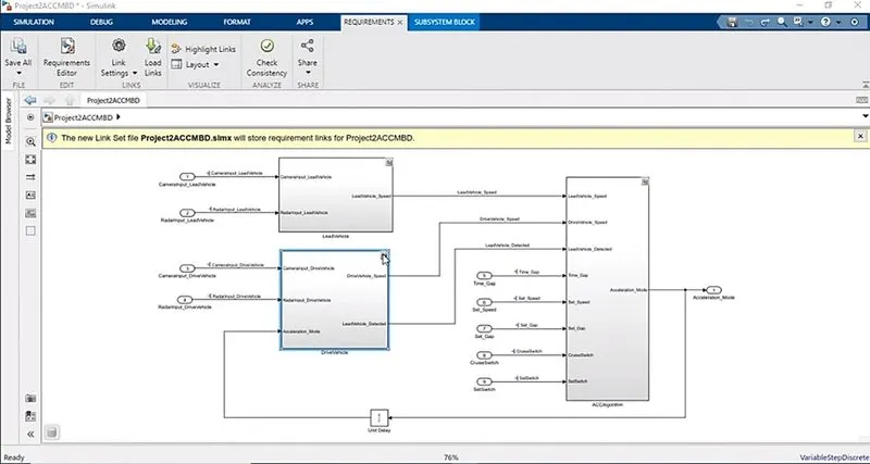
After requirement traceability is done, we can find a n icon in each subsystems top right corner as shown below:
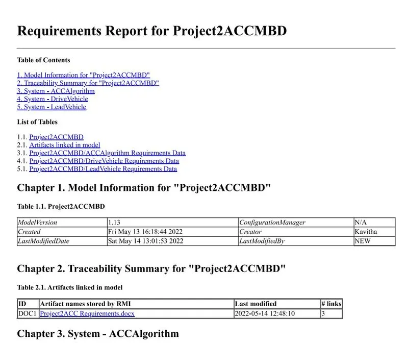
Requirement report sample shown below:
3. Model advisor check results
Selecting the file for which advisor is needed to be run
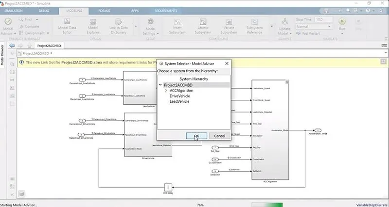
Selecting the rules - here standard ones are selected
Results obtained after model advisor check - 507 passed and 315 warnings
sample model advisor report
4. Code generation part
This below image shows selection of c codde - build- generate c code steps
Result of code generation is shown below:
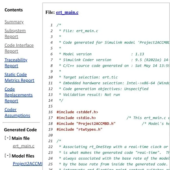
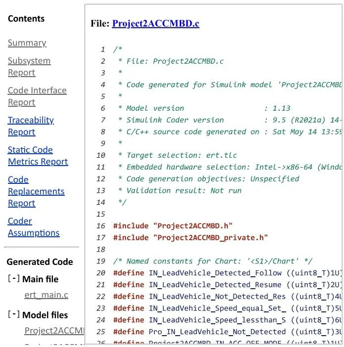
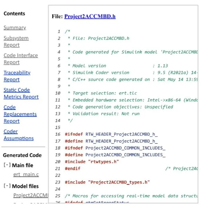
Reports of code generatiopn are given below for ert_main.c and .c and .h alone
Conclusion:
Thus development of Adaptive Cruise Control model algorithm as per the Requirement Document using MATLAB Simulink is successfully done. Also I followed all the MBD related processes for the developed model like: Requirement Tagging & Traceability, SLDD creation, Configuration Parameter changes, Model Advisor check & finally done with Code Generation.