Project 2 - Development of Coolant Temperature Software Component Meter
Project 2 - Development of Coolant Temperature Software Component Meter
Aim:
The project aims at developing a Coolant Temperature Software Component Meter using simulink and doing the following list of tests and verifications:
- Simulink Model Design
- Sldd creation & linking
- Requirement Tagging & Traceability
- Model Advisor JMAAB check
- Using Fixed point toolbox to convert the data types
- Auto code generation
- Simulink design verifier usage for design verification
- Writing functional test cases , developing MIL & SIL harness and doing validation and taking coverage reports
- Next stage is Polyspace Static Code Analysis
- Followingly we have to do test the automation using Simulink Test Manager - baseline and back to back testing.
Description of the project:
The Engine Coolant Temperature Sensor is a temperature variable resistor, which usually has a negative temperature coefficient. It is a two wired thermistor immersed in coolant and measures its temperature. The temperature value is then given to the ECU. From there, the vehicle ECU will use this temperature information to either continue operating or adjust certain engine functions, always working to keep the engine temperature at an optimal level. Coolant Temperature Meter receives Engine Coolant Temperature Signal from the CAN whenever Ignition is turned ON. Subsequently, Signal Processing is performed for Coolant Temperature Indication.
Procedure:
Step1: Open Matlab - new blank simulink model and save it as VV_P2.slx model
Step2: As per the requirements given, design the Coolant system using subsystems to control the temperature by varyingthe engine parameters.Also open model explorer and create SLDD file and save it and link it with the model.
Step3: Now the requirements given in the description are turned into excel file with corresponding Id no’s and details are put in another column and saved for proceeding with the next requirement linking process.
Step4: Requirement toolbox usage procedure:
- In apps Open Requirement editor and keep your excel document also ready.
- Follow the given procedures to complete requirement adding & linking:
- Click the new requirement set option in the requirement editor window - give the file name same as model name and save as .slreqx file - now right click on model.slreqx and add 1st requirement index no:1 and similarly add 2nd,3rd,4th till 14 requirements by copying the id and details and pasting it in corresponding properties of requirements 1 to 14 - save it.
- For linking: go to model and select 1st block - then come to requirement toolbox and and select 1st index and right click on it and select "link from Coolant_Temperature_Meter_SWC subsystem" - now the link gets added to first subsystem - similarly do this for 2nd,3rd until the 14th index requirements [ view show links] - save all - Under Matlab model you will be able to see the .slmx and .slreqx files and then select export - generate report - modify the settings of reports if you want else click ok and get your tagging report ready.
Step5:JMAAB Guidance check
Now goto model advisor and select the project name and JMMAB standards under task and given run selected checks and generate the advisor report. If any failures are found, the goto model redo everything and check again.
Step6: Auto code Generation
Goto model settings - configuration parameters - set solver as fixed step size 0.01, discrete and code generation is enabled and target is chosen and give build or generate code option. you will get your codes and also generate the reports for .c and .h files.
Step7:SLDV Usage procedure
- Goto apps and open design verifier toolbox and do the below mentioned procedure:
- Select Design Error Detection - open error detection settings - in configuration parameters, set mem array time as :300, under reports - enable it & under error detection you have to choose divide by zero and integer overflow and make solver settings as fixed step size of 0.01 and click on check compatibility - then run the detect design error option.
- Then again in design verifier tool select test generation - select advisor - in configuration parameters, set mem array time as :300, under reports - enable it & under error detection you have to choose divide by zero and integer overflow and make solver settings as fixed step size of 0.01 and click on test coverage enable, as well select MCDC coverage option and apply and click ok and run the advisor and after that advisor run, run the main test generator and generate the reports for error detection and test coverage report as well.
- The test generation process itself will self/auto generate the test cases and MIL environment, so we can get the harness model and coverage report for MIL as well.
Step8: MIL and Coverage Tests using Functional Test cases
As the result of running SLDV we will get ML harness and auto generated test cases so that we can run it again or take the coverage directly from SLDV tool.
Else write the functional test cases in excel and create MIL harness environment using signal builder and upload the test case and run the coverage and get the report.
Step9: SIL and Coverage Tests using Functional Test cases
Make configuration settings and right click on your model and select 's' function creation. You will get build s function - enable it and build - you will get a new harness model which is nothing but your SIL harness. To that add the signal builder and scope and other necessary data conversion blocks and inside signal builder, import the excel test cases and run the coverage for the SIL harness test. generate the report.
Step10: Go to polyspace tool and run the polyspace bug finder and polyphase code prover after making necessary configuration settings and get the reports.
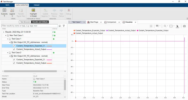
Step11: Open Simulink test manager toolbox and select baseline testing first- open new test file - make necessary requirements linkings and other settings and run the test and get the report. Also again select back to back testing and make necessary settings changes and run the test to get the comparison of MIL vs SIL coverage report via back to back testing.
Simulation model:
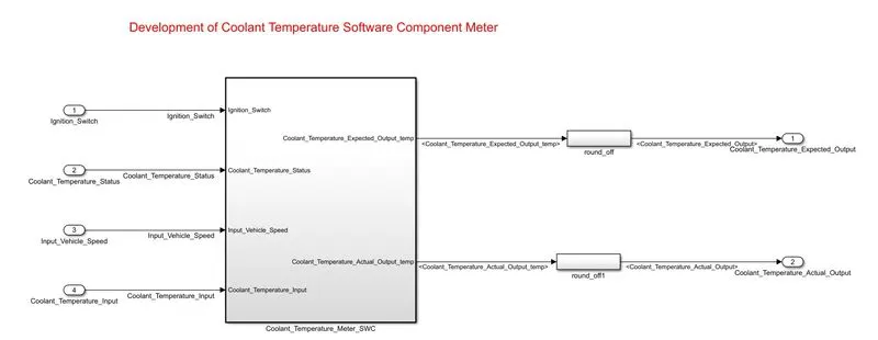
The main simulink model of the Coolant Temperature Software Component Meter system is shown below:
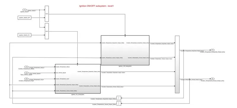
The Level1 subsystem - Ignition ON/OFF
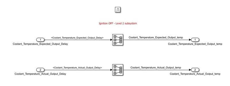
Level2 - Ignition OFF subsystem
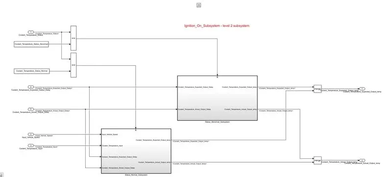
Level 2- Ignition ON subsystem
\
Level 3 subsystems are given below: For Normal & abnormal conditions
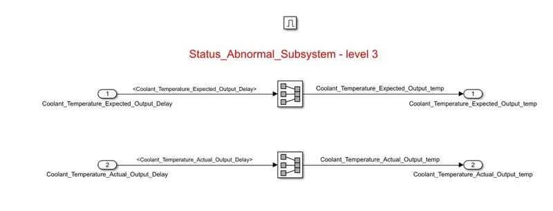
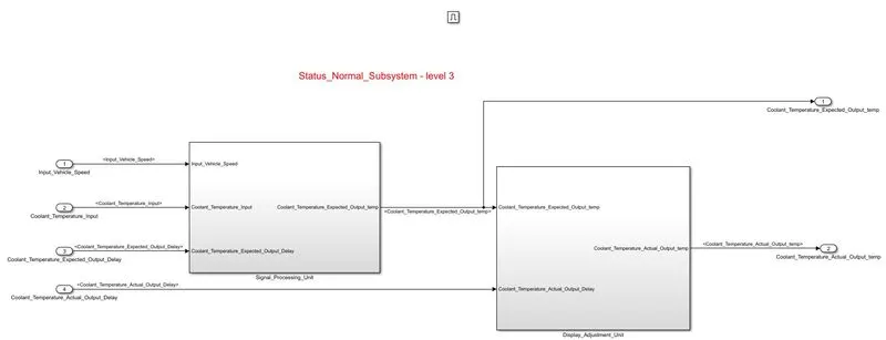 Level 4 subsystems are given below: Control action signal processing unit
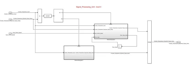
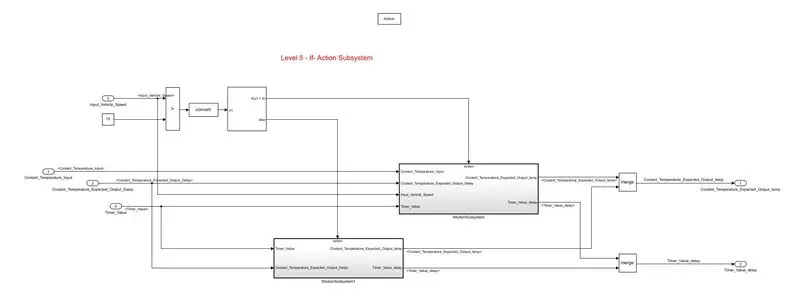
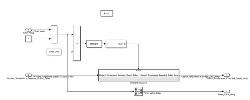
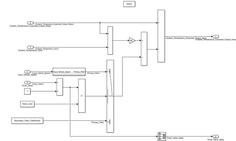
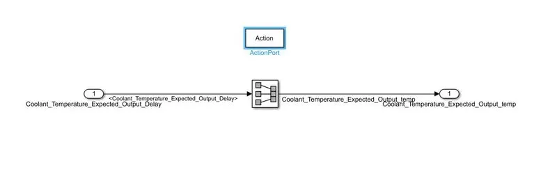
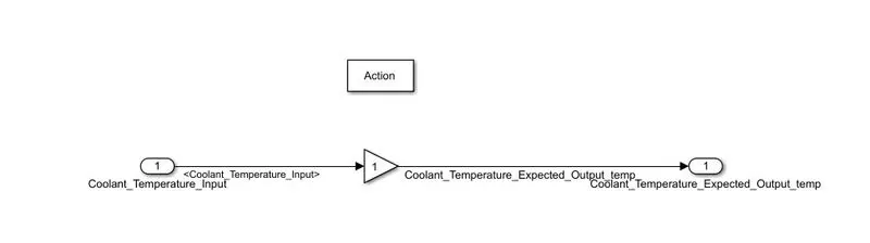
Level 5 subsystems are given below of signal processing & display units:
Results & Displays:
The following are the results obtained at each stage of modelling & design verification.
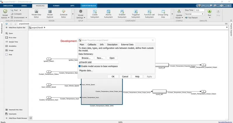
SLDD file creation using model explorer and Linking it to the model is shown below:
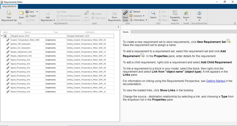
The below image shows the requirement Tagging part output view using Requirement editor:
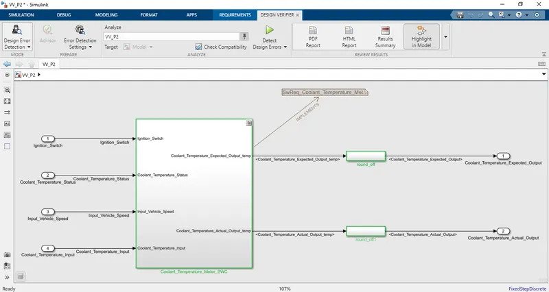
The model shows the requirement traceability paths & links:
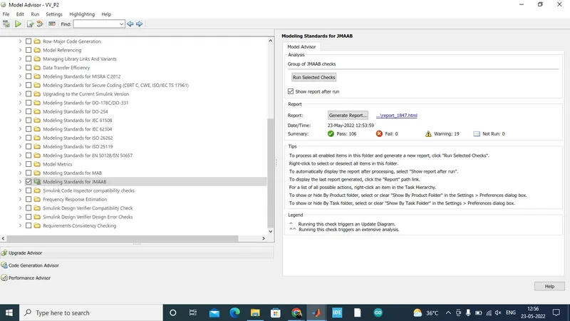
Model advisor check for JMAAB - results are shown below:
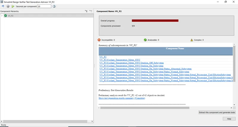
SLDV design verifier Test generation output is as below:
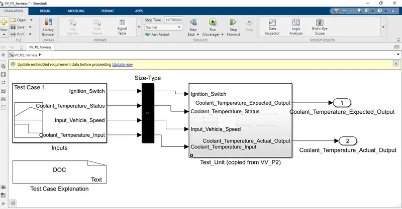
MIL harness model:
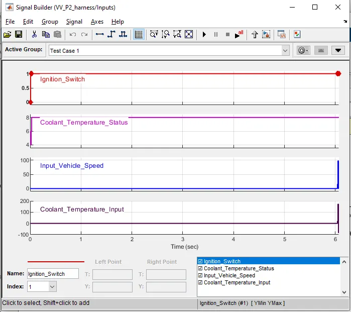
Signal Builder viewis as below:
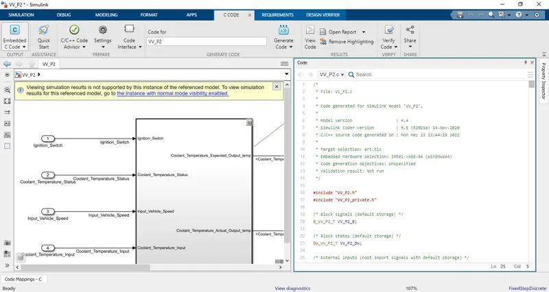
Auto Code generation part output is shown below:
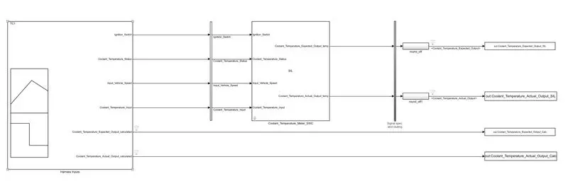
SIL harness model:
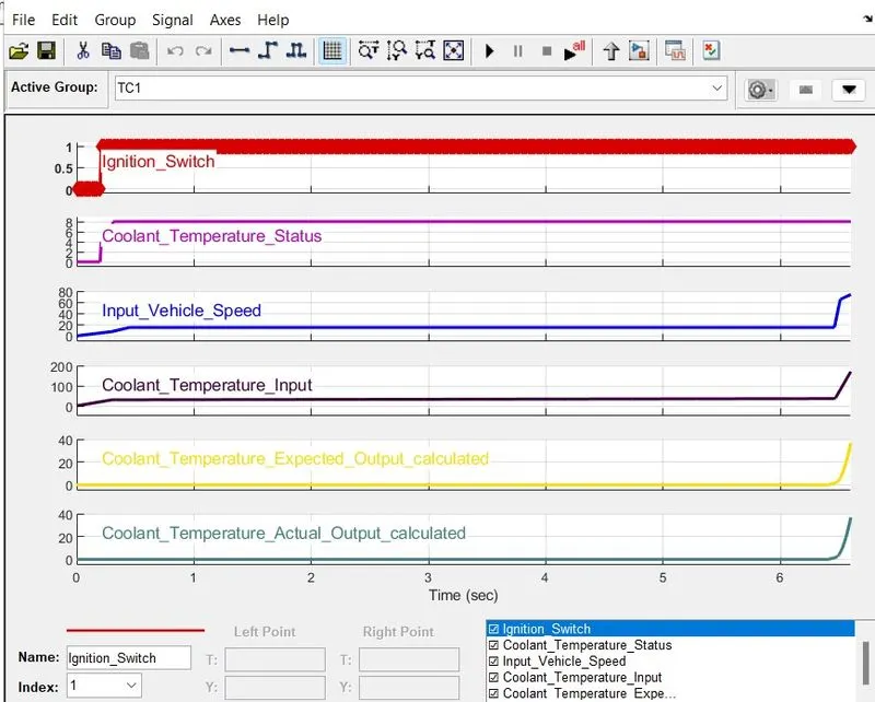
Signal Builder view:
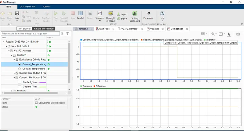
Simulink test manager - Baseline & back to back testing results:
Baseline comparison chart results:
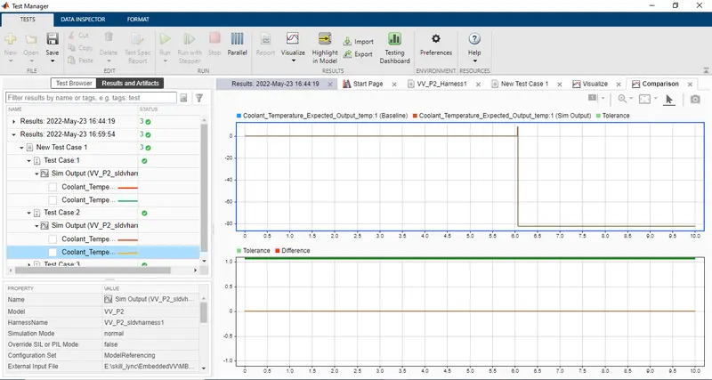
back to back testing comparison chart output:
Conclusion:
The project for developing a Coolant Temperature Software Component Meter is thus designed via a simulink model. And the following things were achieved.
- Simulink Model Design
- Sldd creation & linking
- Requirement Tagging & Traceabillity
- Model Advisor JMAAB check
- Auto code genertion
- Simulink design verifier usage for design test verification
- Writing functional test cases , developing MIL & SIL harness and doing validation and taking coverage reports
- Followingly we have done the test automation using Simulink Test Manager - baseline and back to back testing.
Stage by stage images were shown above and the attachments hold the corresponding reports.