Project 2-Highway Assistant-Lane Changing Assistant
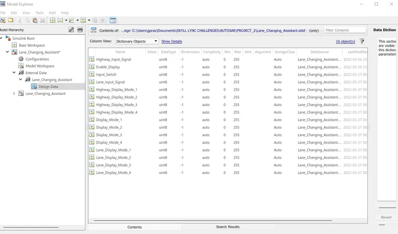
Step 1) Creating the sldd file for the given variables
Input Signals:
|
Name of the Signal |
Data Type |
Range |
|
Highway_Input_Signal |
uint8 |
0 - 255 |
|
Enable_Display |
uint8 |
0 – 255 |
|
Input_Switch |
uint8 |
0 – 255 |
|
Lane_Input_Signal |
uint8 |
0 - 255 |
Local Signals:
|
Name of the Signal |
Data Type |
Range |
|
Highway_Display_Mode_1 |
uint8 |
0 - 255 |
|
Highway_Display_Mode_2 |
uint8 |
0 – 255 |
|
Highway_Display_Mode_3 |
uint8 |
0 – 255 |
|
Highway_Display_Mode_4 |
uint8 |
0 – 255 |
|
Lane_Display_Mode_1 |
uint8 |
0 – 255 |
|
Lane_Display_Mode_2 |
uint8 |
0 – 255 |
|
Lane_Display_Mode_3 |
uint8 |
0 – 255 |
|
Lane_Display_Mode_4 |
uint8 |
0 – 255 |
Output Signals:
|
Name of the Signal |
Data Type |
Range |
|
Display_Mode_1 |
uint8 |
0 - 255 |
|
Display_Mode_2 |
uint8 |
0 – 255 |
|
Display_Mode_3 |
uint8 |
0 – 255 |
|
Display_Mode_4 |
uint8 |
0 - 255 |
Step 2) Prepare the model as per the requirement 1 and form it as a subsystem
Requirement No 1 [Highway_DisplayUnit]:
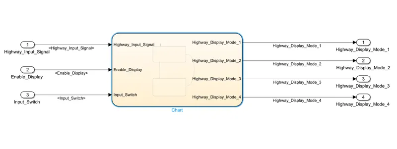
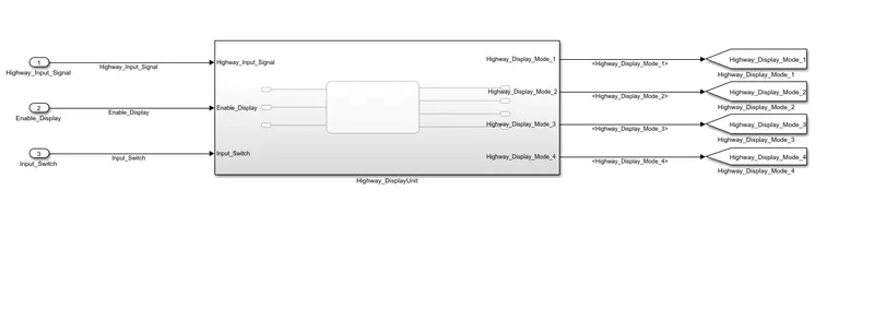
- Inputs to this particular subsystem are “Highway_Input_Signal”, “Enable_Display”, “Input_Switch”.
- These three input signals, when assigned to a particular value will give output signals of specific value.
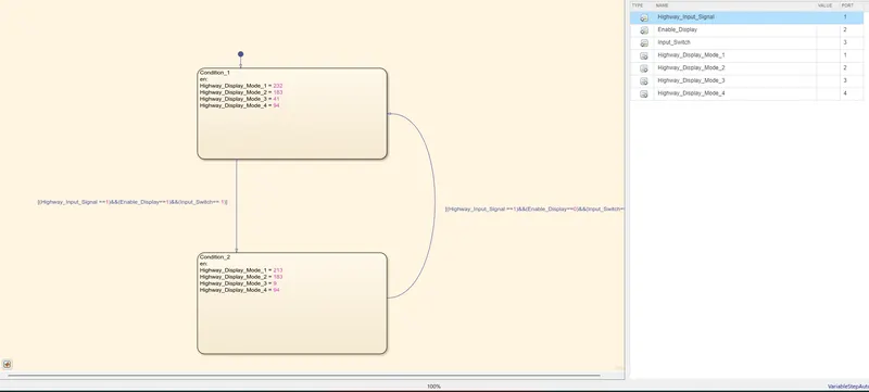
- The output signals are “Highway_Display_Mode_1”, “Highway_Display_Mode_2”, “Highway_Display_Mode_3”, “Highway_Display_Mode_4”. The requirement must be implemented in the form of a Stateflow logic.
|
Condition |
Action |
|
Highway_Input_Signal = 1 Enable_Display = off Input_Switch = on |
Highway_Display_Mode_1 = 232 Highway_Display_Mode_2 = 183 Highway_Display_Mode_3 = 41 Highway_Display_Mode_4 = 94 |
|
Highway_Input_Signal = 1 Enable_Display = on Input_Switch = on |
Highway_Display_Mode_1 = 213 Highway_Display_Mode_2 = 183 Highway_Display_Mode_3 = 9 Highway_Display_Mode_4 = 94 |
Step 3) Prepare the model as per the requirement 2 and form it as a subsystem
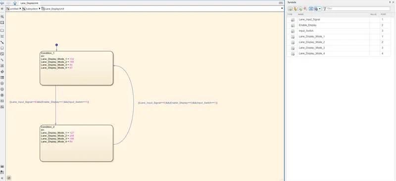
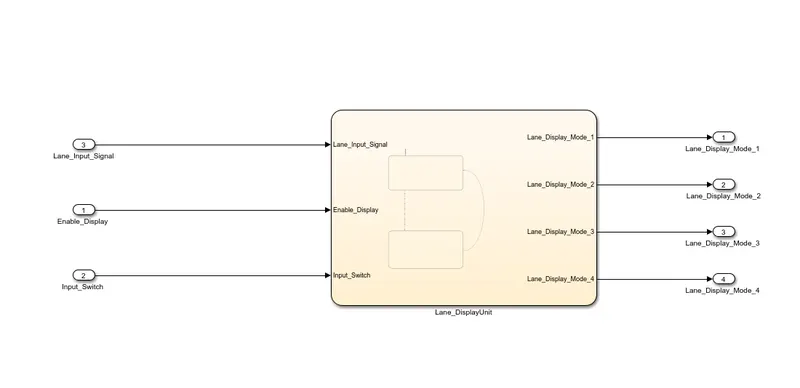
- Inputs to this particular subsystem are “Enable_Display”, “Input_Switch”, “Lane_Input_Signal”.
- These three input signals, when assigned to a particular value will give output signals of specific value.
- The output signals are “Lane_Display_Mode_1”, “Lane_Display_Mode_2”, “Lane_Display_Mode_3”, “Lane_Display_Mode_4”. The requirement must be implemented in the form of Stateflow logic.
|
Condition |
Action |
|
Lane_Input_Signal= 6 Enable_Display = off Input_Switch = on |
Lane_Display_Mode_1 = 132 Lane_Display_Mode_2 = 185 Lane_Display_Mode_3 = 54 Lane_Display_Mode_4 = 67 |
|
Lane_Input_Signal= 6 Enable_Display = on Input_Switch = on |
Lane_Display_Mode_1 = 127 Lane_Display_Mode_2 = 248 Lane_Display_Mode_3 = 186 Lane_Display_Mode_4 = 84 |

Step 4) Prepare the model as per the requirement 3 and form it as a subsystem
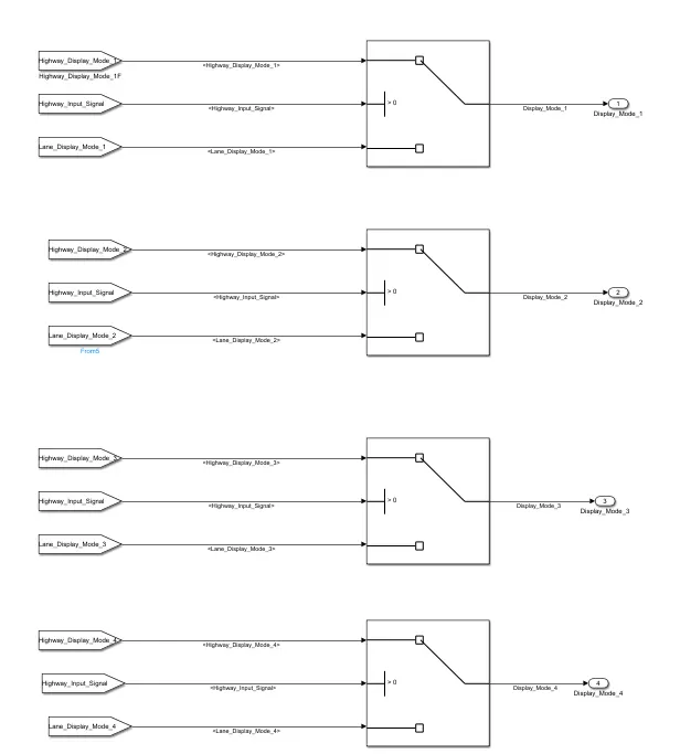
Signals coming from both subsystems “Highway_Display_Mode_1” & “Lane_Display_Mode_1” are given as inputs to a switch block which will have input signal “Highway_Input_Signal” given as 2nd input to the switch block. Corresponding output from this particular switch block is output signal “Display_Mode_1”.
Signals coming from both subsystems “Highway_Display_Mode_2” & “Lane_Display_Mode_2” are given as inputs to a switch block which will have input signal “Highway_Input_Signal” given as 2nd input to the switch block. Corresponding output from this particular switch block is output signal “Display_Mode_2”.
Signals coming from both subsystems “Highway_Display_Mode_3” & “Lane_Display_Mode_3” are given as inputs to a switch block which will have input signal “Highway_Input_Signal” given as 2nd input to the switch block. Corresponding output from this particular switch block is output signal “Display_Mode_3”.
Signals coming from both subsystems “Highway_Display_Mode_4” & “Lane_Display_Mode_4” are given as inputs to a switch block which will have input signal “Highway_Input_Signal” given as 2nd input to the switch block. Corresponding output from this particular switch block is output signal “Display_Mode_4”.
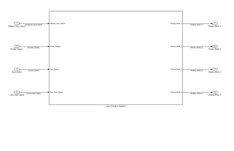
Step 5) After creating the subsystem for requirement3 , combine requirement 1 2 & 3 and give names to the respective signals as per their port of origin ,propagate the respective signals and resolve the signals..Making the subsystem for the both combined requirement the final model of the system will look as shown below.
Step 6) Now link the requirement document to the respective the subsystem.
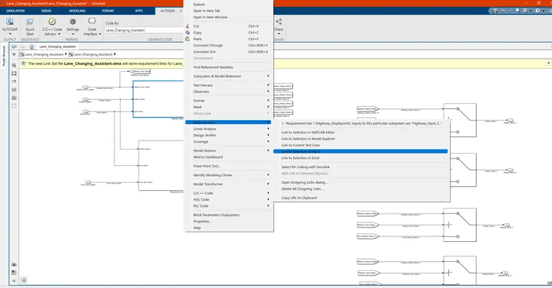
step 7) In order to Autosar Port Mapping for the model , open the model and run the model in order to check if the model is not having any sorts of error.From the App tab of the simulink menu select Autosar Component.
Once selected, it will ask for converting the code generation to autosar.tlc. Click OK. And to verify, go to the configuation parameters and check the same. Also verify that the solver selected must be 'Fixed step'
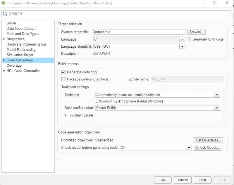
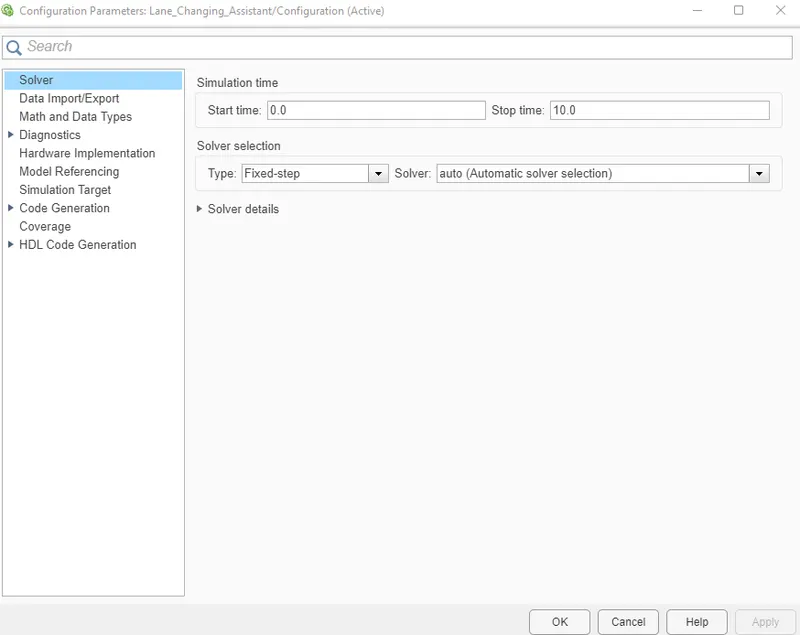
8) Go to Autosar dictionary option by going to code interface and select autosar dictionary
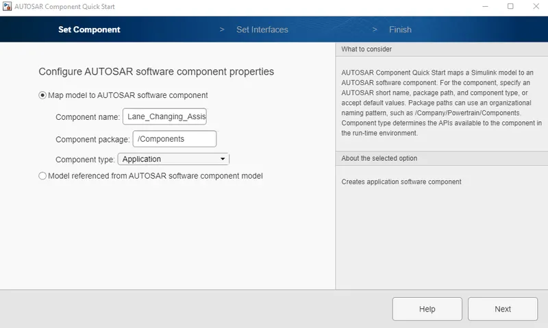
Edit the XML option first as ahown below
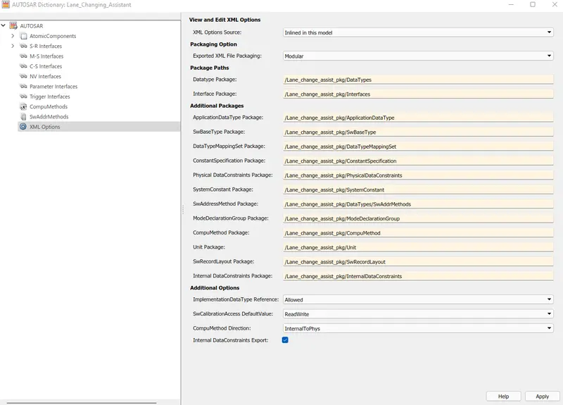
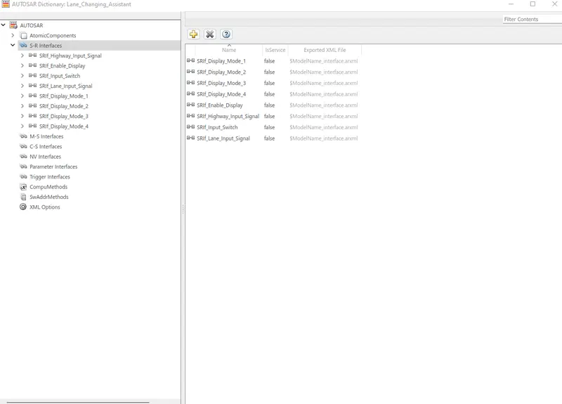
Add the sender reciever interface signals as per the nomenclature given in the model with prefix as SRIf_ for both input and output ports. Also name their respective data elements with prefix DE_ as shown below
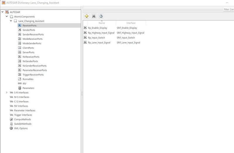
Add the input port as per the nomenclature given in the model for input ports with prefix as Rp_ and link with the respective interface signal as shown below
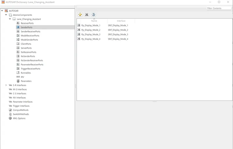
Add the output port as per the nomenclature given in the model for output ports with prefix as Pp_ and link with the respective interface signal as shown below
Add the runnables
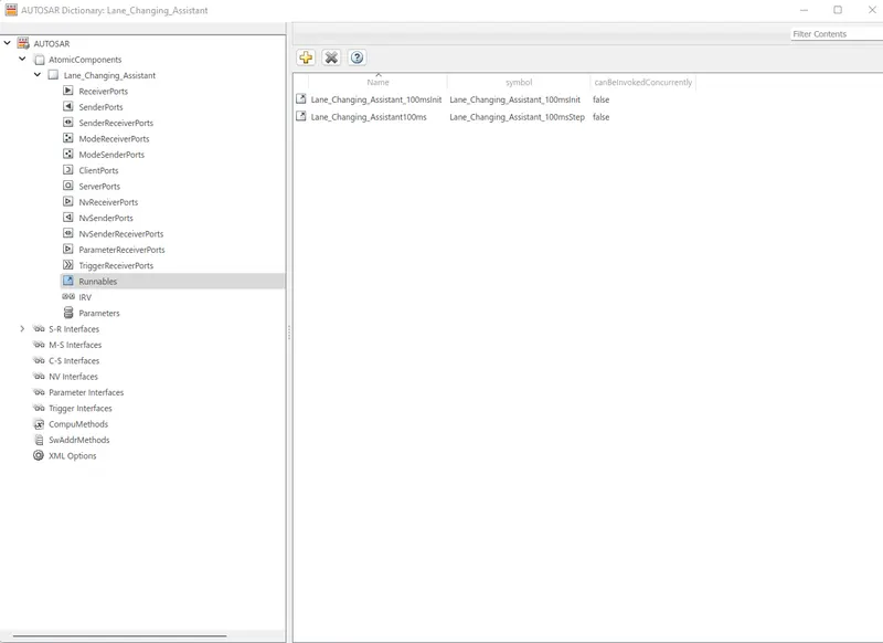
9) select the option of Code Mappings -AUTOSAR SW Component option from left bottom corner and link all the runnables, input port to their data elements and output port to their data elements.
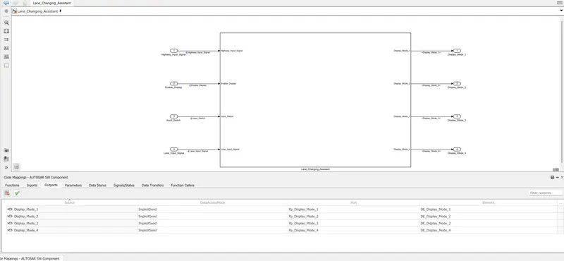
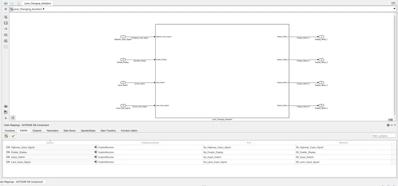
Then click on the refresh button to update the model.
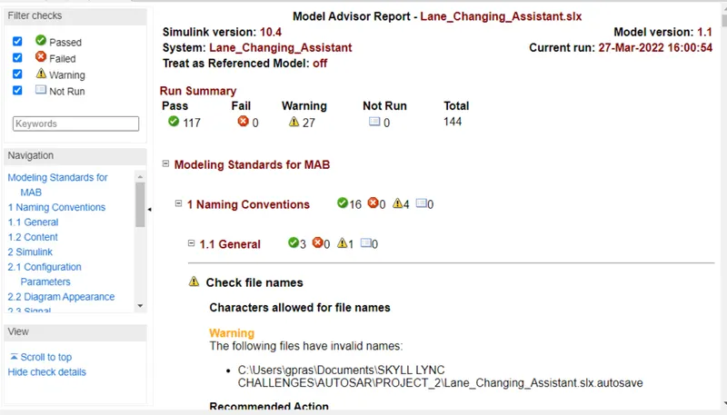
10) Run the model advisory and generate the report
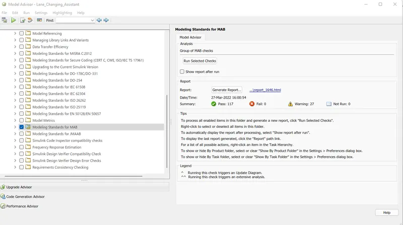
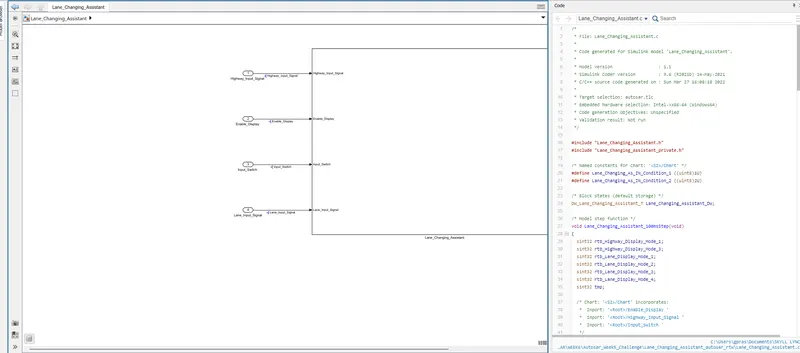
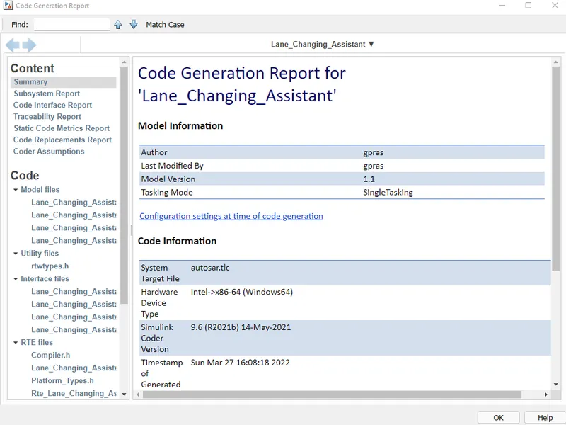
11) Run the code generator
/*
 * File: Lane_Changing_Assistant.c
 *
 * Code generated for Simulink model 'Lane_Changing_Assistant'.
 *
 * Model version                  : 1.1
 * Simulink Coder version         : 9.6 (R2021b) 14-May-2021
 * C/C++ source code generated on : Sun Mar 27 16:08:18 2022
 *
 * Target selection: autosar.tlc
 * Embedded hardware selection: Intel->x86-64 (Windows64)
 * Code generation objectives: Unspecified
 * Validation result: Not run
 */

#include "Lane_Changing_Assistant.h"
#include "Lane_Changing_Assistant_private.h"

/* Named constants for Chart: '<S2>/Chart' */
#define Lane_Changing_As_IN_Condition_1 ((uint8)1U)
#define Lane_Changing_As_IN_Condition_2 ((uint8)2U)

/* Block states (default storage) */
DW_Lane_Changing_Assistant_T Lane_Changing_Assistant_DW;

/* Model step function */
void Lane_Changing_Assistant_100msStep(void)
{
  sint32 rtb_Highway_Display_Mode_1;
  sint32 rtb_Highway_Display_Mode_3;
  sint32 rtb_Lane_Display_Mode_1;
  sint32 rtb_Lane_Display_Mode_2;
  sint32 rtb_Lane_Display_Mode_3;
  sint32 rtb_Lane_Display_Mode_4;
  sint32 tmp;

  /* Chart: '<S2>/Chart' incorporates:
   *  Inport: '<Root>/Enable_Display '
   *  Inport: '<Root>/Highway_Input_Signal '
   *  Inport: '<Root>/Input_Switch '
   */
  if (Lane_Changing_Assistant_DW.is_active_c3_Lane_Changing_Assi == 0U) {
    Lane_Changing_Assistant_DW.is_active_c3_Lane_Changing_Assi = 1U;
    Lane_Changing_Assistant_DW.is_c3_Lane_Changing_Assistant =
      Lane_Changing_As_IN_Condition_1;
    rtb_Highway_Display_Mode_1 = 232;
    rtb_Highway_Display_Mode_3 = 41;
  } else if (Lane_Changing_Assistant_DW.is_c3_Lane_Changing_Assistant ==
             Lane_Changing_As_IN_Condition_1) {
    rtb_Highway_Display_Mode_1 = 232;
    rtb_Highway_Display_Mode_3 = 41;
    if ((Rte_IRead_Lane_Changing_Assistant100ms_Rp_Highway_Input_Signal_DE_Highway_Input_Signal
         () == 1) &&
        (Rte_IRead_Lane_Changing_Assistant100ms_Rp_Enable_Display_DE_Enable_Display
         () == 1) &&
        (Rte_IRead_Lane_Changing_Assistant100ms_Rp_Input_Switch_DE_Input_Switch()
         == 1)) {
      Lane_Changing_Assistant_DW.is_c3_Lane_Changing_Assistant =
        Lane_Changing_As_IN_Condition_2;
      rtb_Highway_Display_Mode_1 = 213;
      rtb_Highway_Display_Mode_3 = 9;
    }
  } else {
    /* case IN_Condition_2: */
    rtb_Highway_Display_Mode_1 = 213;
    rtb_Highway_Display_Mode_3 = 9;
    if ((Rte_IRead_Lane_Changing_Assistant100ms_Rp_Highway_Input_Signal_DE_Highway_Input_Signal
         () == 1) &&
        (Rte_IRead_Lane_Changing_Assistant100ms_Rp_Enable_Display_DE_Enable_Display
         () == 0) &&
        (Rte_IRead_Lane_Changing_Assistant100ms_Rp_Input_Switch_DE_Input_Switch()
         == 1)) {
      Lane_Changing_Assistant_DW.is_c3_Lane_Changing_Assistant =
        Lane_Changing_As_IN_Condition_1;
      rtb_Highway_Display_Mode_1 = 232;
      rtb_Highway_Display_Mode_3 = 41;
    }
  }

  /* End of Chart: '<S2>/Chart' */

  /* Chart: '<S3>/Lane_DisplayUnit' incorporates:
   *  Inport: '<Root>/Enable_Display '
   *  Inport: '<Root>/Input_Switch '
   *  Inport: '<Root>/Lane_Input_Signal'