Project 2 - Development of TFT Cluster Speedometer Software Component
TFT Cluster Speedometer:
Cluster Instrument receives the signals from other ECU via CAN bus interface. It also receives commands from the driver via steering wheel buttons. The signals are then processed by the Cluster ECU, after which the Cluster ECU may send the vehicle information to the LCD or light the LEDs and so forth, according to the results. Therefore, the Cluster ECU can be viewed as a carrier of the information flow.
Blocks Used:
- Constant
- From and Goto blocks
- Input/Output Ports
- Compare to constant block
- Saturation Block
- Division
- Subtration
- Gain
- Triggered Subsystems
- Product
- Abs
- Switch
We have developed a simulink model which satisfies the above requirements.
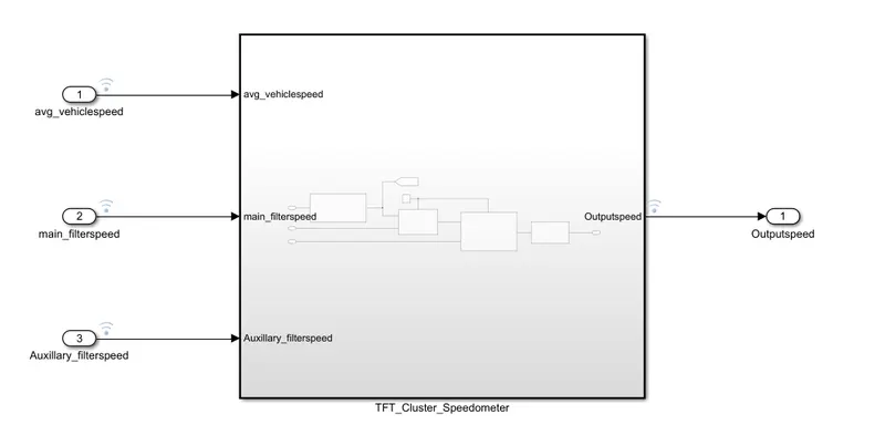
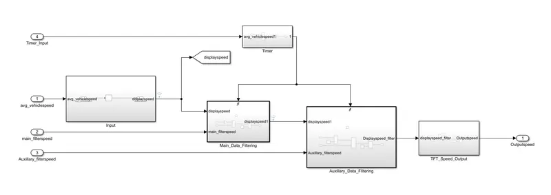
Now we have created subsytems for each requirement that are stated in the query.
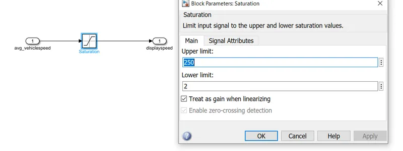
Calculating TFT Display Speed:
Average Vehicle Speed would be displayed only if its between 2 kmph & 250 kmph. Any value outside this range will be discarded by its lower limit & upper limit
When Average Vehicle Speed is < 2 kmph, DisplaySpeed = 2 kmph
When Average Vehicle Speed is in between 2 kmph & 250 kmph, Display Speed = Average Vehicle Speed
When Average Vehicle Speed is > 250 kmph, Display Speed = 250 kmph
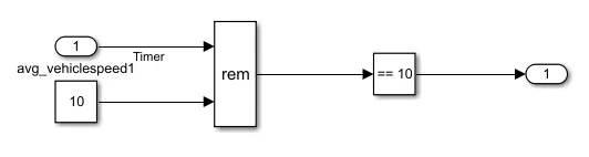
Timer Ckt:
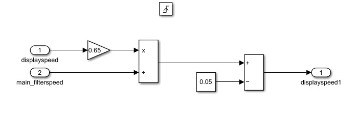
1.2 Main Data Filtering:
Main Data Filtering subsystem will be activated for every 10th millisecond
DisplaySpeed1 (t) = ((DisplaySpeed (t) x 0.65)/ Main Filter Speed Value)- 0.05
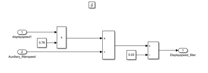
1.3 Auxiliary Data Filtering:
Auxiliary Data Filtering subsystem will be activated for every 10th millisecond
DisplaySpeed_Filter (t) = ((DisplaySpeed1 (t) x 0.78)/ Auxillary Filter Speed Value) - 0.03
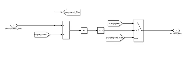
1.4 TFT Speed Output:
If |(DisplaySpeedFilter - DisplaySpeed)| > 1.5
{
Vehicle Speed Display = DisplaySpeed
}
else
{
Vehicle Speed Display = DisplaySpeed Filter
}
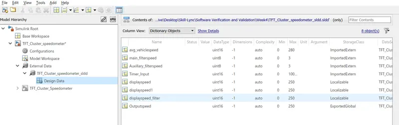
Now we have created a Data dictionary for providing necessary input values, local values and the resultant output too.
Here for convenience we have integrated requirements to the blocks for easy understanding.
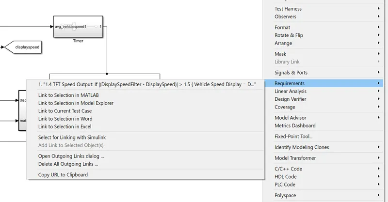
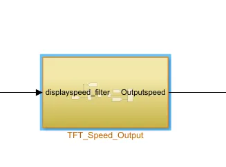
After selecting text from the word file, we need to right click on correspondant block and then we need to follow the above steps. If it is successfully done the block is highlighted as shown below:
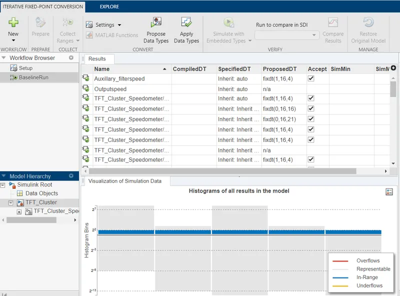
Fixed Point Tool:
For Model Advisor JMAAB Check:
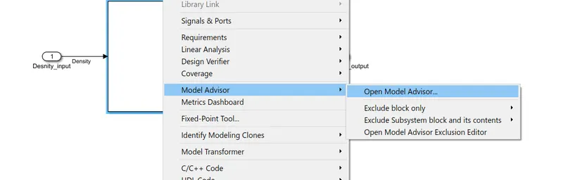
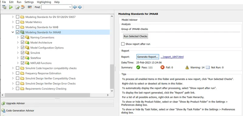
Detailed report of JMAAB Model Advisor Test has been attached below.
Coverage of MIL and SIL Analysis:
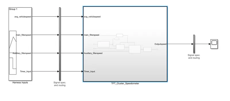
Above is the MIL Harness model, to the signal map the designed test cases to run the analysis
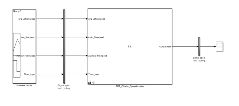
Above is the SIL Harness model, to the signal map the designed test cases to run the analysis
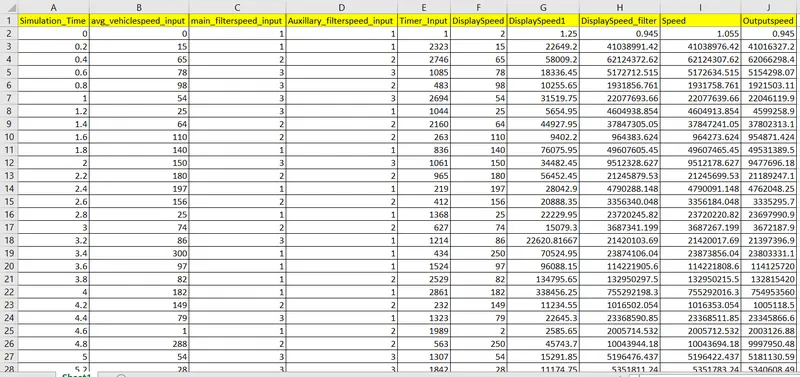
These are the test cases that are fed to model to complete the MIL and SIL analysis.
Fixed Point Tool:
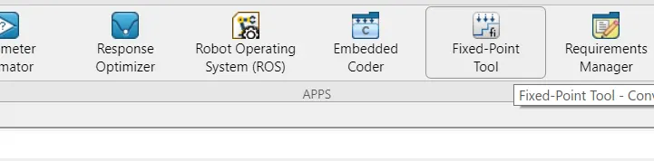
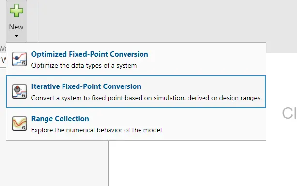
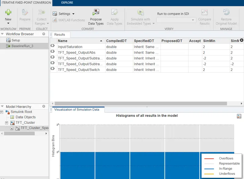
Propsed Data Types can be observed below
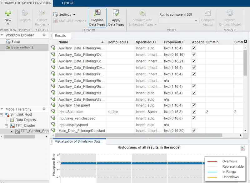
SLDV Tool:
In order to perform this go to Apps and select "Design Verifier" tool set from the drop down.
Now run the advisor to check the compatability
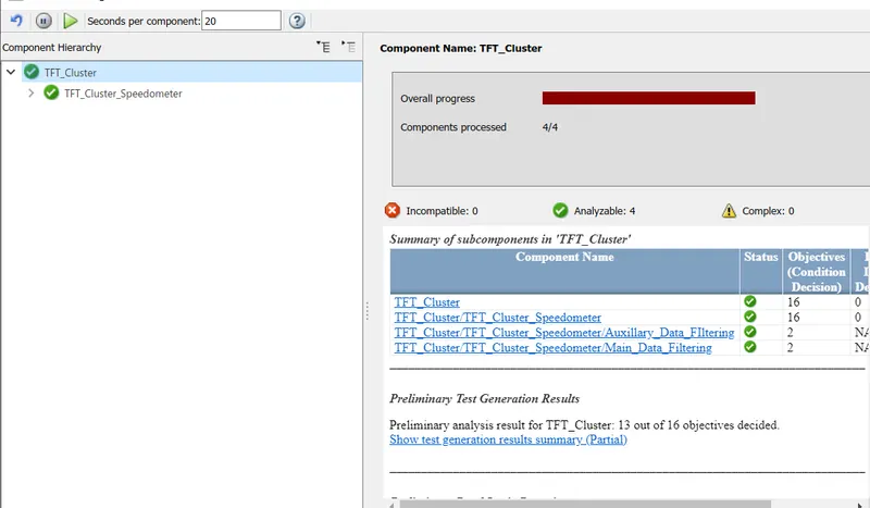
From here we came to know that our system is free from dead logics and good to perform test generation.
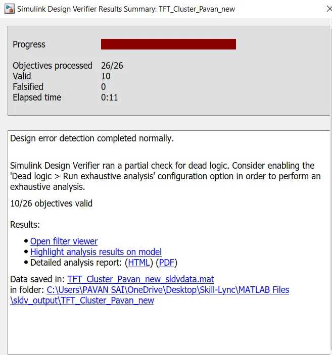
Design Error Analysis:
Autocode Generation fo the Model:
Goto Apps and select "Embedded C code" to generate the .c and .h files for the above model
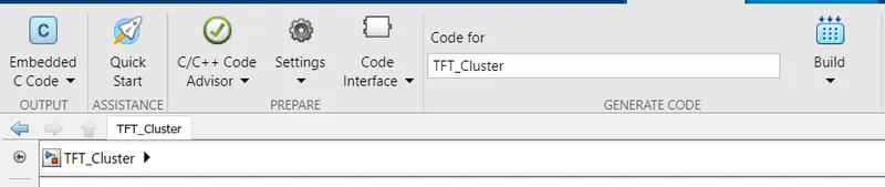
Now click on "Build" option to generate the codes.
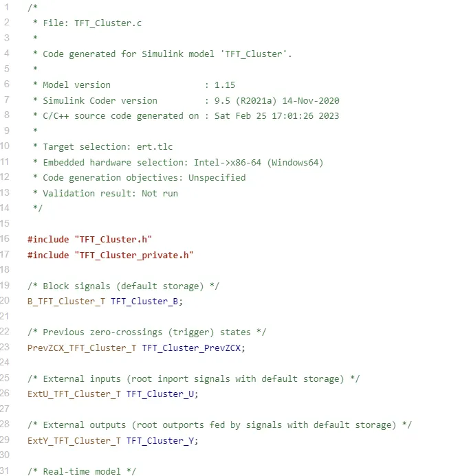
Above is the .c code of the model
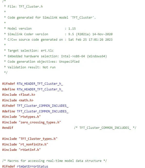
Above is the .h file of the model
Step-by-Step Procedure for Polyspace Test Analysis:
- After completion of modelling compile it and check for any warnings or errors.
- Now goto Apps Section and look for "Polyspace" and then click on it.
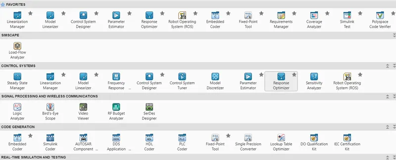
- Now in this page we have two tests that can be performed -- Bug Finder and Code Prover
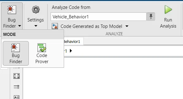
- Now select "Code Prover" then a dailog appears to run the analysis
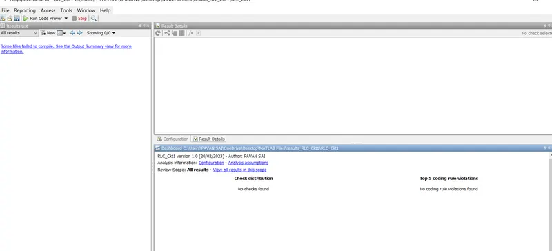
- Now from here click on "Run Code Prover" to initiate the analysis and to generate the code eventually once the analysis is done by the tool
Necessary "Configuration" parameters that need to be checked when intitialising the Test analysis
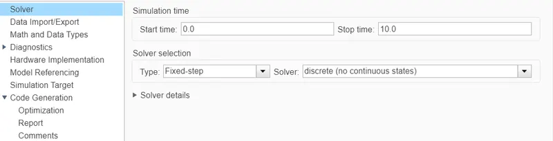
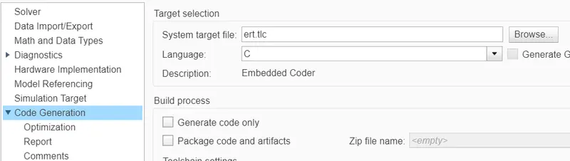
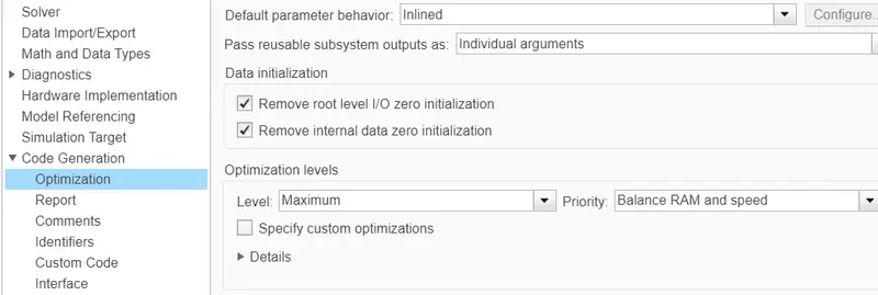
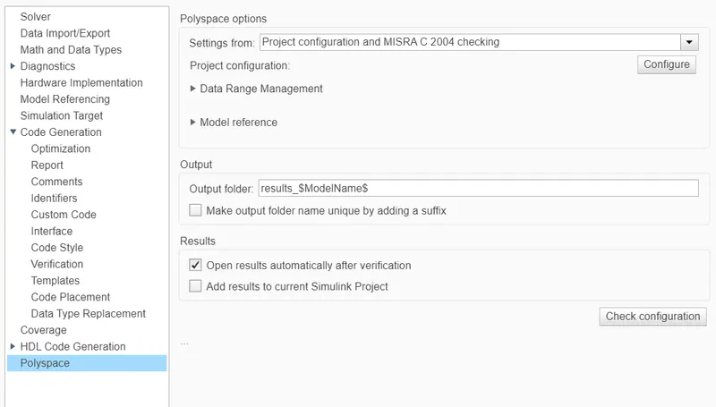
Once these all parameters are checked then we can run the analysis by using a licensed Polyspace Tool box.
Baseline Testing:
Initially goto APPS and select click on "Simulink Test"
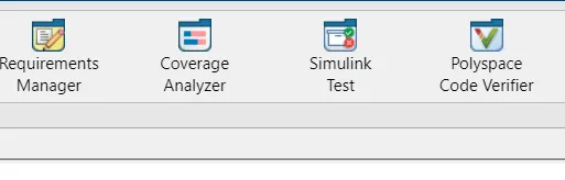
Now click on "Simulink Test Manager" which opens up the Manager view to perform the Tests
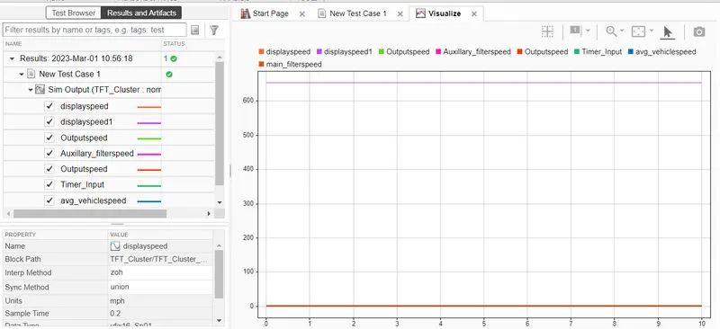
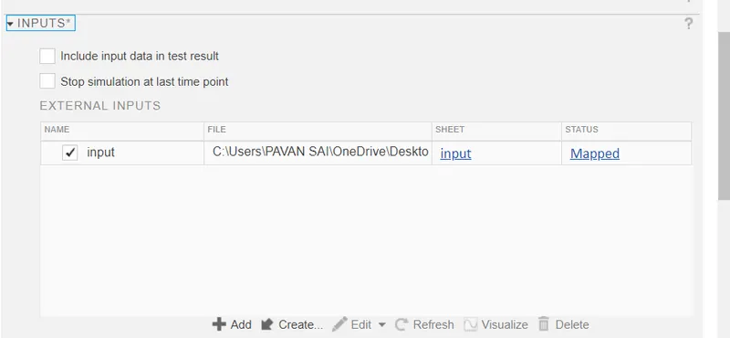
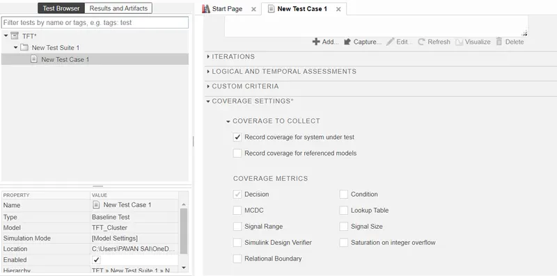
Next for "System Under Test" browse the .slx file
Back2Back Testing:
Initially goto APPS and select click on "Simulink Test"
Now click on "Simulink Test Manager" which opens up the Manager view to perform the Tests
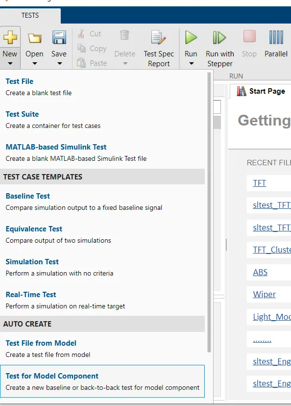
After running the extensive back 2 back testing, a report is generated with necessary details.
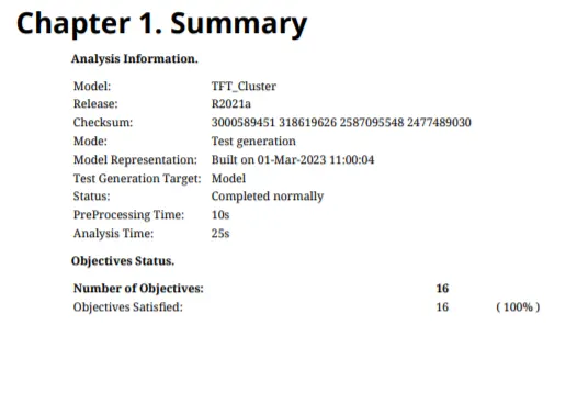
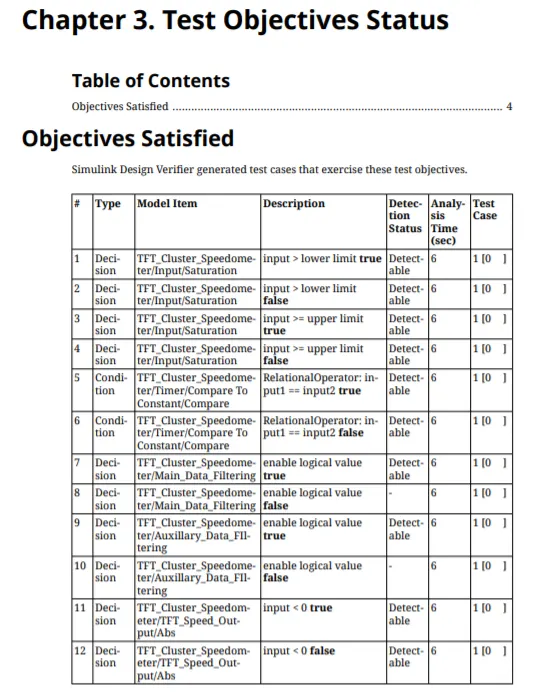
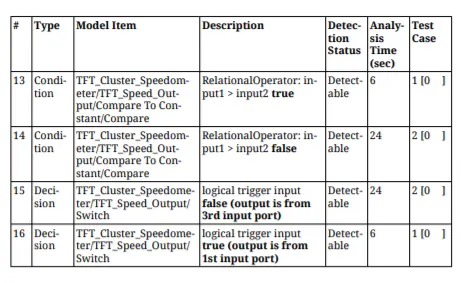
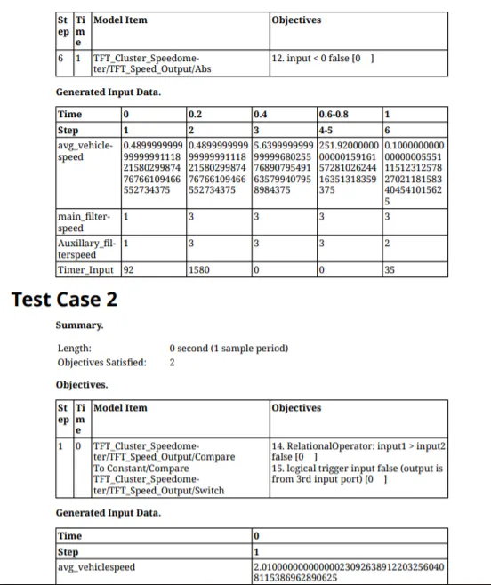
Detailed report and necessary simulink files are attached below in a zipped folder.