Project 2 - Development of TFT Cluster Speedometer Software Component
A TFT (Thin Film Transistor) cluster speedometer software component is critical to a vehicle's instrument cluster system. The instrument cluster, often located behind the steering wheel, provides essential information to the driver, and the speedometer is a key element of this display.
- Hardware Integration:
The speedometer software interfaces with the vehicle's hardware, particularly the speed sensor. The speed sensor measures the vehicle's speed, and the software processes this information for display on the TFT screen. - Data Processing:
The software processes the raw data from the speed sensor, converting it into a format suitable for display. This involves calculating the vehicle's speed and possibly other related information like distance travelled, average speed, or fuel efficiency. - User Interface Design:
The software is responsible for designing and rendering the user interface on the TFT screen. This includes creating a visually appealing and easily readable display of the speed and other relevant information. Consideration is given to factors such as font size, colour, and layout. - Real-Time Updates:
The speedometer component must update the displayed information in real-time to reflect vehicle speed changes. Real-time responsiveness is crucial for providing accurate and timely information to the driver. - Integration with Other Systems:
The software component integrates with other vehicle systems, such as the engine control unit (ECU) or transmission control unit (TCU), to access additional data. This integration ensures that the speedometer can display comprehensive information about the vehicle's status. - Error Handling:
Robust error-handling mechanisms are implemented to address issues that may arise, such as sensor malfunctions or communication errors. The software should provide meaningful error messages or indicators to alert the driver in case of problems. - Customization Features:
To enhance user experience, the speedometer software may include customization features. Drivers might be able to choose between different display themes, units of measurement (e.g., mph or kmph), or additional information to be shown on the screen. - Testing & Calibration:
Rigorous testing is conducted to ensure the accuracy and reliability of the speedometer readings. Calibration processes may be implemented to fine-tune the accuracy of the speed readings based on factors like tire size or gear ratios. - Compliance with Regulations:
The software component must comply with safety and regulatory standards governing in-vehicle displays. This includes adhering to guidelines related to font size, colour contrast, and other user interface aspects to ensure readability and minimize distraction for the driver. - Optimization for Performance:
Given embedded systems' often limited computing resources, the software is optimized for performance and resource efficiency. This involves efficient code design and implementation to ensure smooth operation within the constraints of the vehicle's hardware. - Documentation:
Comprehensive documentation is provided for the software, detailing its design, functionality, and any maintenance or troubleshooting instructions. This documentation is essential for future development, updates, and maintenance.
The TFT cluster speedometer software component is crucial in enhancing the overall driving experience by providing accurate and easily accessible information to the driver.
Simulink Model:
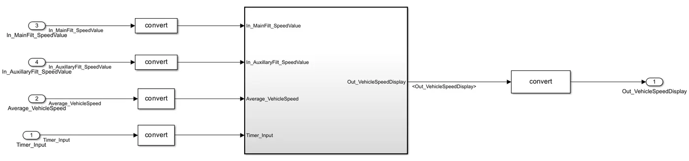
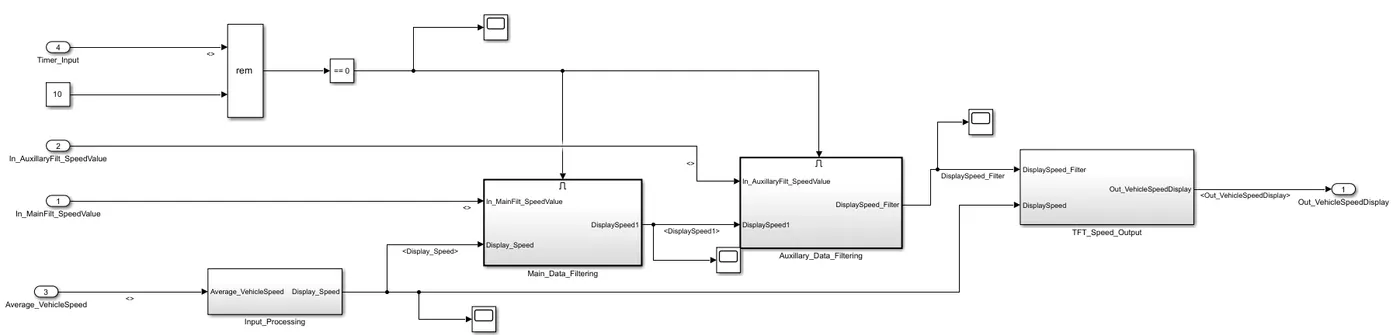
Requirements:
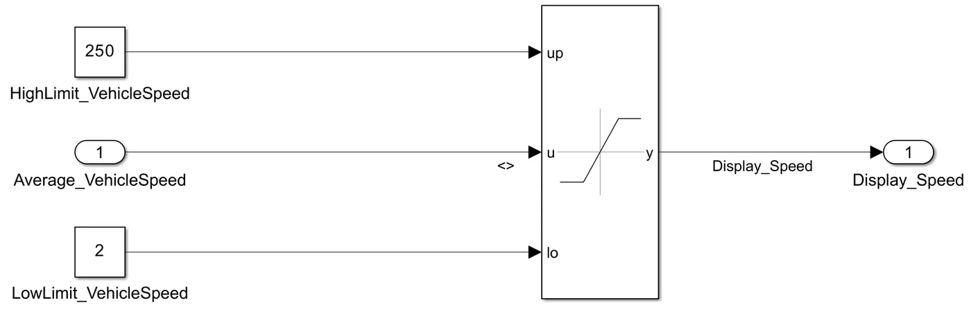
1.1 Calculating TFT Display Speed
Average Vehicle Speed would be displayed only if it's between 2 kmph & 250 kmph.
When Average Vehicle Speed is < 2 kmph, DisplaySpeed = 2 kmph
When Average Vehicle Speed is in between 2 kmph & 250 kmph, DisplaySpeed = Average Vehicle Speed
When Average Vehicle Speed is > 250 kmph, DisplaySpeed = 250 kmph
1.2 Main Data Filtering
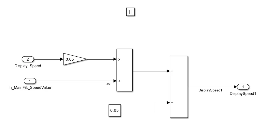
Main Data Filtering subsystem will be activated for every 10th millisecond
DisplaySpeed1 (t) = ((DisplaySpeed (t) x 0.65)/ Main Filter Speed Value) - 0.05
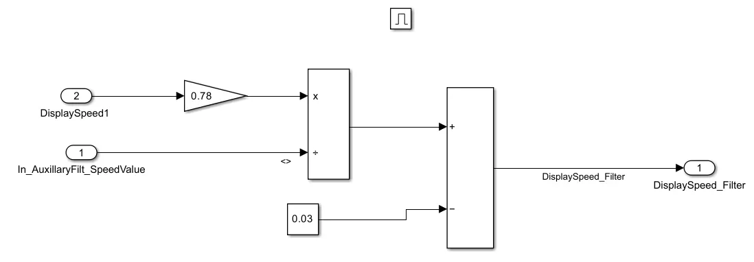
1.3 Auxiliary Data Filtering
Auxiliary Data Filtering subsystem will be activated for every 10th millisecond
DisplaySpeed_Filter (t) = ((DisplaySpeed1 (t) x 0.78)/ Auxiliary Filter Speed Value) - 0.03
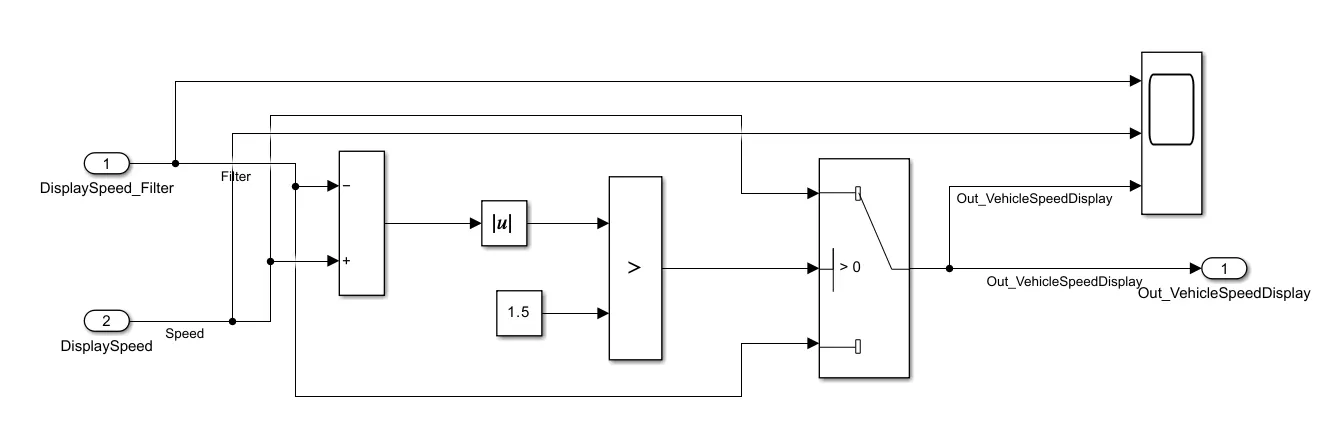
1.4 TFT Speed Output
If |(DisplaySpeedFilter - DisplaySpeed)| > 1.5
{
Vehicle Speed Display = DisplaySpeed
}
else
{
Vehicle Speed Display = DisplaySpeed Filter
}
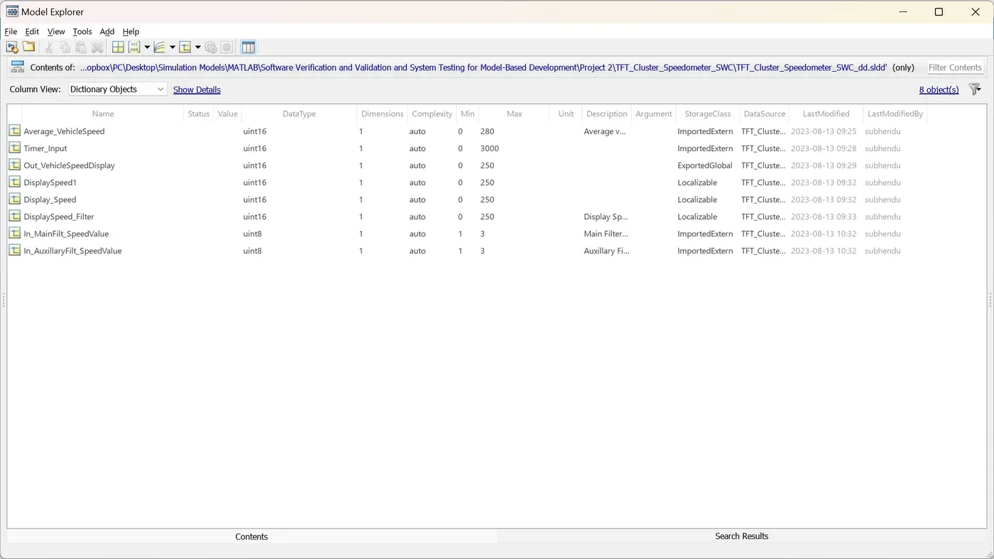
Simulink Data Dictionary
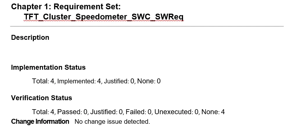
Requirement Tagging Report
Fixed-point Tool
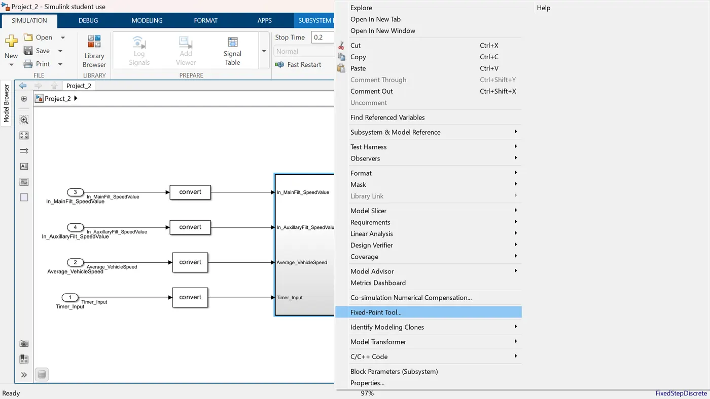
Iterative Fixed-Point Conversion
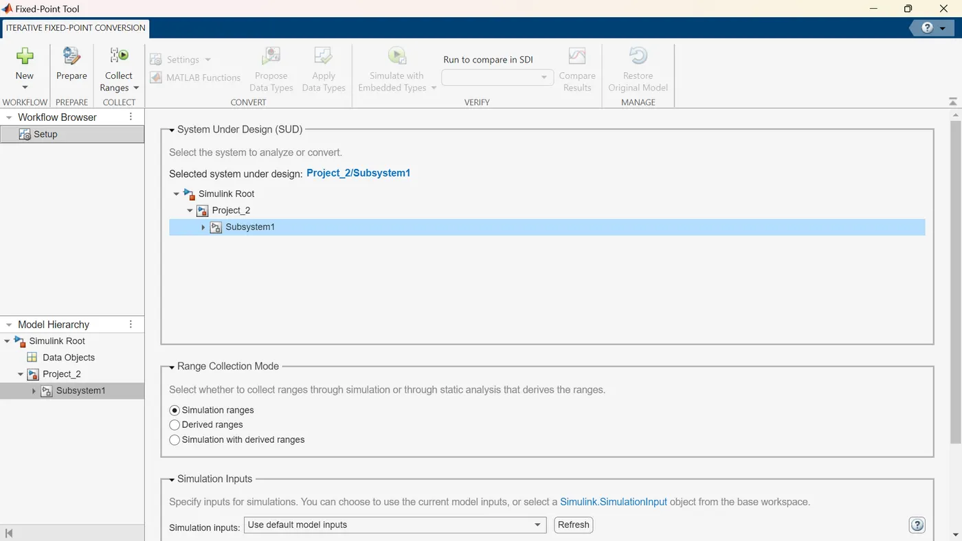
Collect Ranges
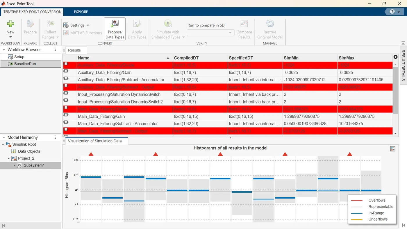
Propose Data Types
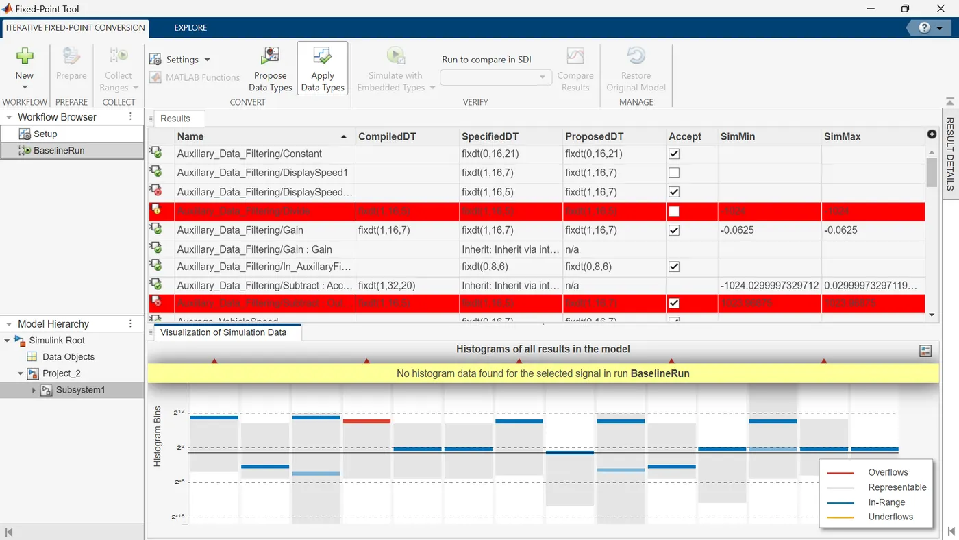
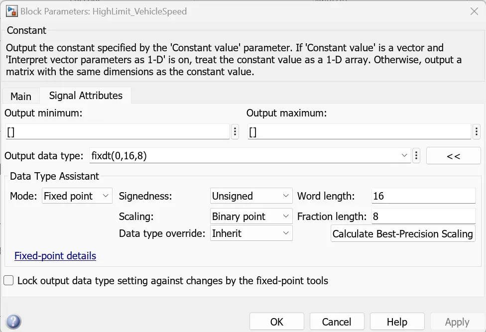
Accept the blocks of the subsystem (Do not accept the red highlighted blocks as they overflow). Apply Data Types
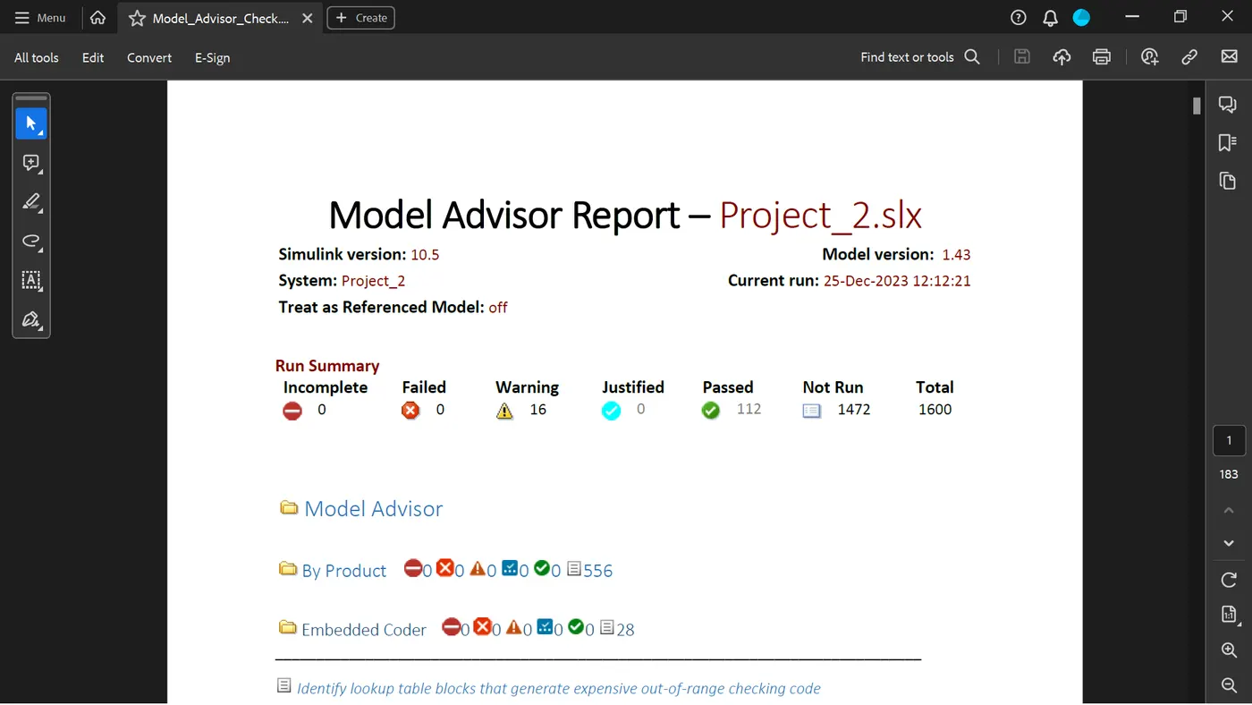
Model Advisor - JMAAB Compliance Report
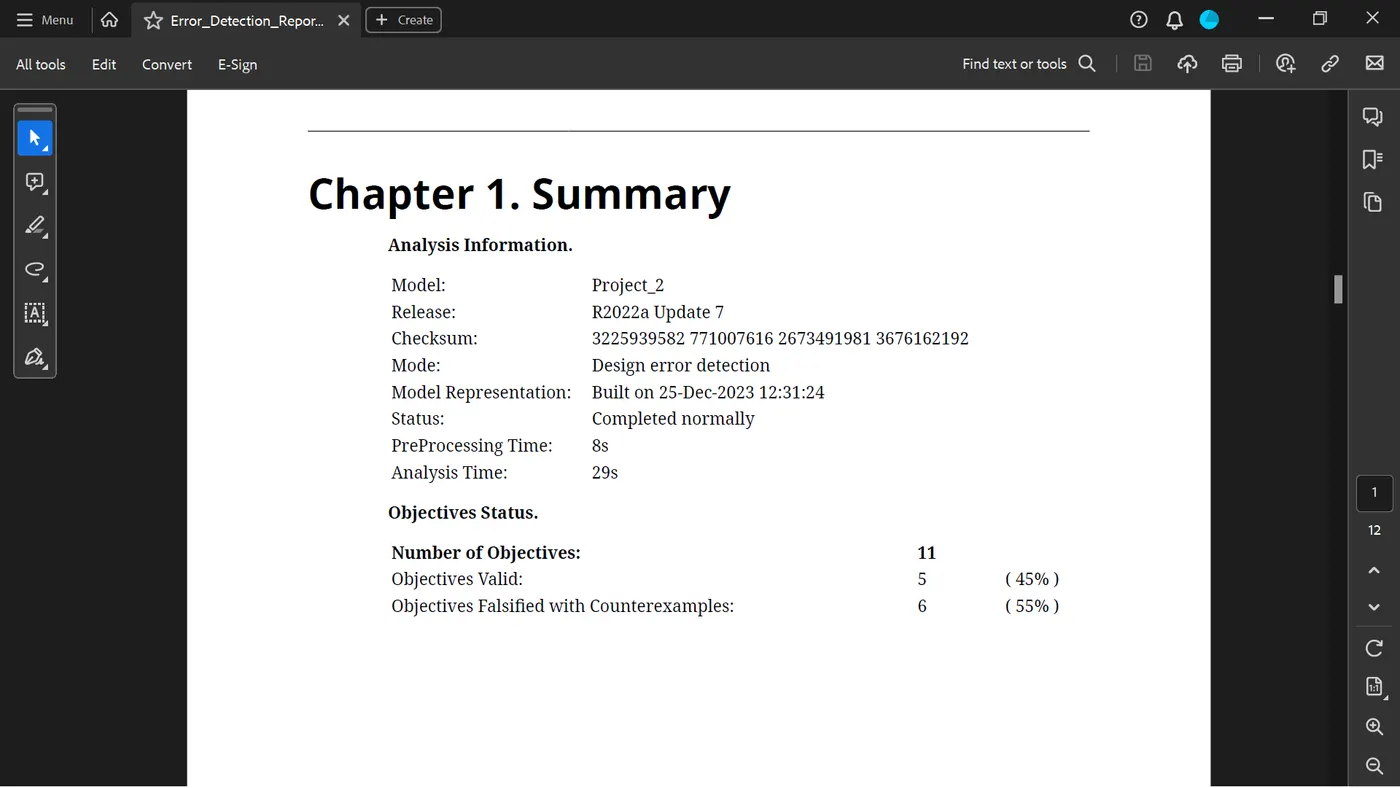
SLDV Design Error Detection Report
Functional Test Case - MIL Harness
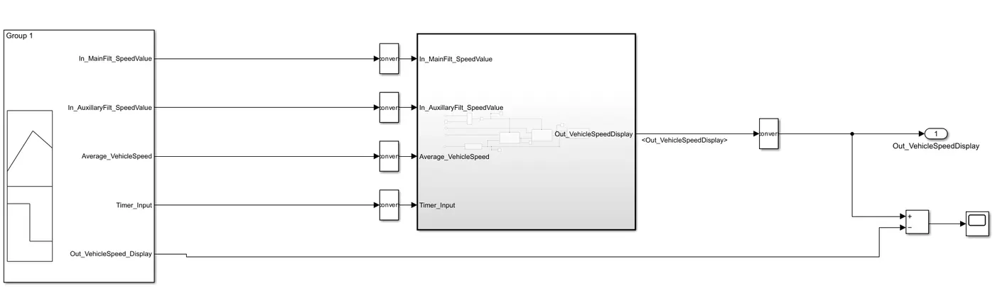
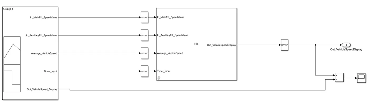
Functional Test Case - SIL Harness
C Code
/*
 * Academic License - for use in teaching, academic research, and meeting
 * course requirements at degree granting institutions only.  Not for
 * government, commercial, or other organizational use.
 *
 * File: ert_main.c
 *
 * Code generated for Simulink model 'Subsystem1'.
 *
 * Model version                  : 3.34
 * Simulink Coder version         : 9.7 (R2022a) 13-Nov-2021
 * C/C++ source code generated on : Mon Dec 25 16:24:08 2023
 *
 * Target selection: ert.tlc
 * Embedded hardware selection: Intel->x86-64 (Windows64)
 * Code generation objectives: Unspecified
 * Validation result: Not run
 */

#include
#include             /* This example main program uses printf/fflush */
#include "Subsystem1.h"                /* Model header file */

/*
 * Associating rt_OneStep with a real-time clock or interrupt service routine
 * is what makes the generated code "real-time".  The function rt_OneStep is
 * always associated with the base rate of the model.  Subrates are managed
 * by the base rate from inside the generated code.  Enabling/disabling
 * interrupts and floating point context switches are target specific.  This
 * example code indicates where these should take place relative to executing
 * the generated code step function.  Overrun behavior should be tailored to
 * your application needs.  This example simply sets an error status in the
 * real-time model and returns from rt_OneStep.
 */
void rt_OneStep(void);
void rt_OneStep(void)
{
  static boolean_T OverrunFlag = false;

  /* Disable interrupts here */

  /* Check for overrun */
  if (OverrunFlag) {
    rtmSetErrorStatus(Subsystem1_M, "Overrun");
    return;
  }

  OverrunFlag = true;

  /* Save FPU context here (if necessary) */
  /* Re-enable timer or interrupt here */
  /* Set model inputs here */

  /* Step the model */
  Subsystem1_step();

  /* Get model outputs here */

  /* Indicate task complete */
  OverrunFlag = false;

  /* Disable interrupts here */
  /* Restore FPU context here (if necessary) */
  /* Enable interrupts here */
}

/*
 * The example main function illustrates what is required by your
 * application code to initialize, execute, and terminate the generated code.
 * Attaching rt_OneStep to a real-time clock is target specific. This example
 * illustrates how you do this relative to initializing the model.
 */
int_T main(int_T argc, const char *argv[])
{
  /* Unused arguments */
  (void)(argc);
  (void)(argv);

  /* Initialize model */
  Subsystem1_initialize();

  /* Attach rt_OneStep to a timer or interrupt service routine with
   * period 0.01 seconds (base rate of the model) here.
   * The call syntax for rt_OneStep is
   *
   *  rt_OneStep();
   */
  printf("Warning: The simulation will run forever. "
         "Generated ERT main won't simulate model step behavior. "
         "To change this behavior select the 'MAT-file logging' option.\n");
  fflush((NULL));
  while (rtmGetErrorStatus(Subsystem1_M) == (NULL)) {
    /*  Perform application tasks here */
  }

  /* Terminate model */
  Subsystem1_terminate();
  return 0;
}

/*
 * File trailer for generated code.
 *
 * [EOF]
 */