Project 2_Design & Analysis of a Hostel building at Guwahati, Assam
AIM:
To provide the analysis in ETABS and SAFE for the given hostel building
INTRODUCTION:
- ETABS is an engineering software product that caters to multi-story building analysis and design. Modeling tools and templates, code-based load prescriptions, analysis methods and solution techniques, all coordinate with the grid-like geometry unique to this class of structure. Basic or advanced systems under static or dynamic conditions may be evaluated using ETABS. For a sophisticated assessment of seismic performance, modal and direct-integration time-history analyses may couple with P-Delta and Large Displacement effects. Nonlinear links and concentrated PMM or fiber hinges may capture material nonlinearity under monotonic or hysteretic behavior. Intuitive and integrated features make applications of any complexity practical to implement. Interoperability with a series of design and documentation platforms makes ETABS a coordinated and productive tool for designs which range from simple 2D frames to elaborate modern high-rises.
- Once modeling is complete, ETABS automatically generates and assigns code-based loading conditions for gravity, seismic, wind, and thermal forces. Users may specify an unlimited number of load cases and combinations.
- Analysis capabilities then offer advanced nonlinear methods for characterization of static-pushover and dynamic response. Dynamic considerations may include modal, response-spectrum, or time-history analysis. P-delta effect account for geometric nonlinearity.
- Given enveloping specification, design features will automatically size elements and systems, design reinforcing schemes, and otherwise optimize the structure according to desired performance measures.
- SAFE offers a single user interface to perform modeling, analysis, design and reporting.SAFE is ideal for modeling foundations, basemats, and footings. Easily model soil supports and zero tension soil models with uplift analysis. The area assignment of soil supports is based on the subgrade modulus, and they automatically adjust whenever the mesh changes. Basemat foundation models can include pedestals, walls, columns, beams, and piles in addition to the foundation area.
- SAFE includes the ability to define post-tensioning in slabs, as banded or distributed tendons. An interactive tendon editor simplifies the task of laying out the tendon profiles. Tendon layouts can also be automated based on strip position and direction.
- SAFE offers a wide range of code-based design features for reinforced concrete and PT beam, slab design and composite steel beams.
- Deformed geometry can be shown after running the analysis. Values are displayed instantaneously when hovering over the model. The deformed geometry can be displayed as filled or line contour plots.
PROCEDURE:
STEP 1:
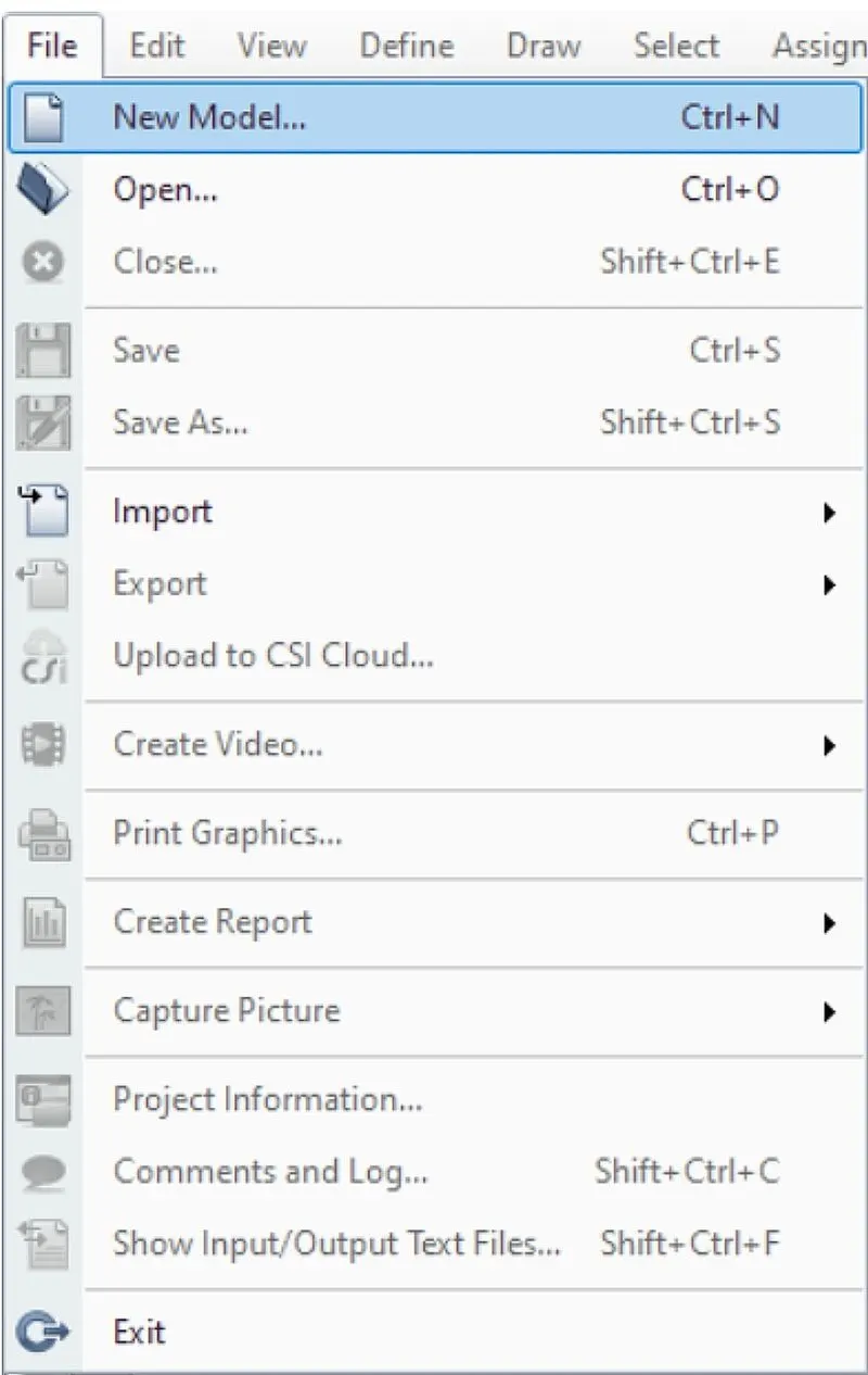
First we have to open etabs software and select new model in the file option at the left side top corner as shown below
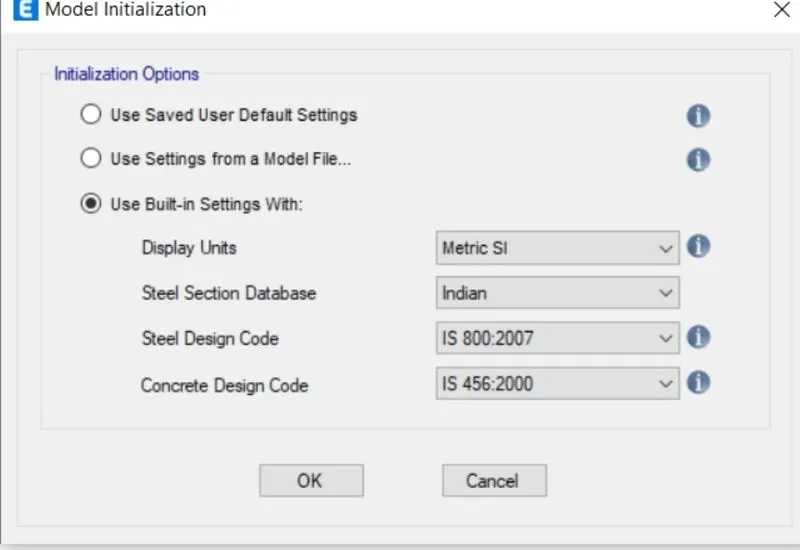
Model intialization interface appears and select USE BUILD IN SETTINGS and make the below mentioned settings
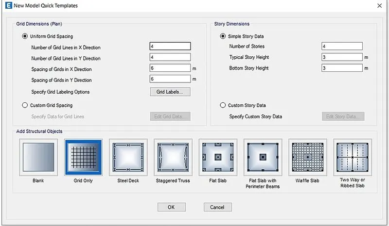
An interface appears as shown in picture. Click the custom grid spacing and maintain the spacing as 4m in both x and y direction
In X and Y direction draw grids as shown in the picture below
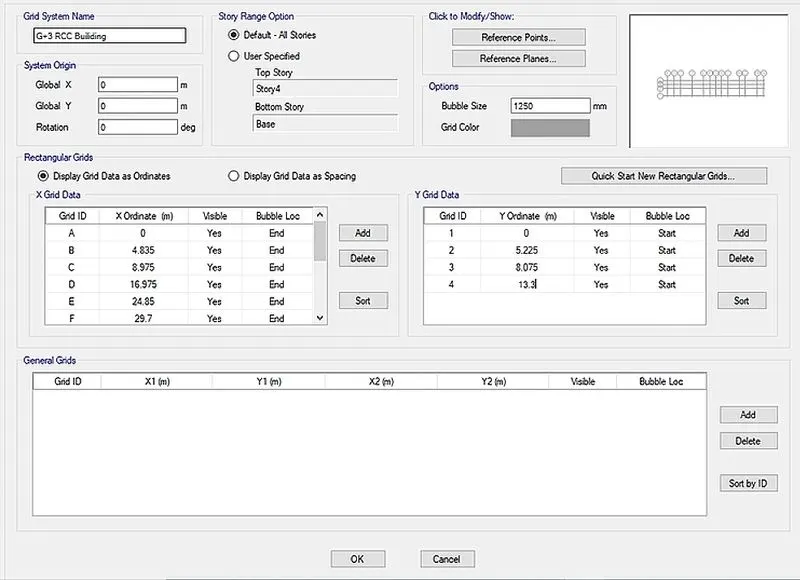
Click OK, a box appears
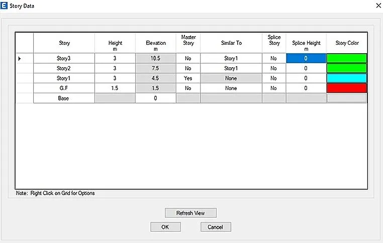
Now we need to add the stories upto 5 story in the story data. Enter the stories upto 5 maintaining height of 3.45m expect for base to plinth which is at 2.4m and 1st storey is entered as master story
STEP 2:
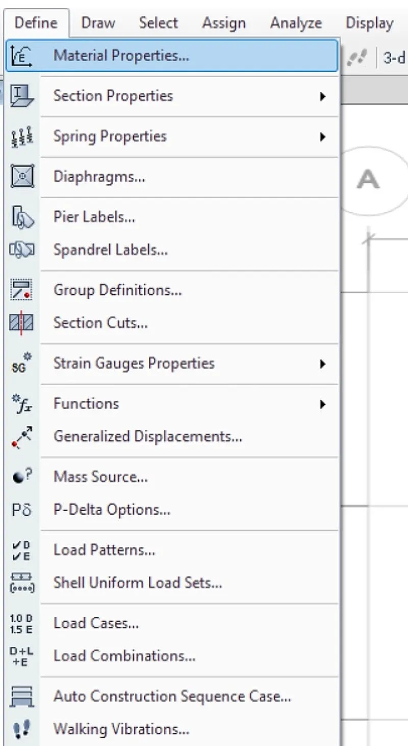
Now go to define option in toolbar and select material properties as shown
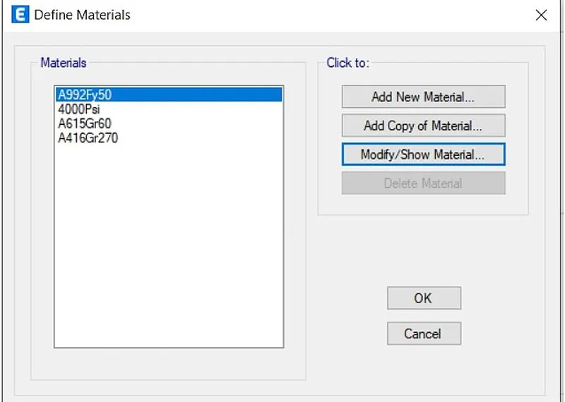
After selecting the material properties the new tab appears and we add new materials by selecting the Add new materials option as shown below
STEP 3:
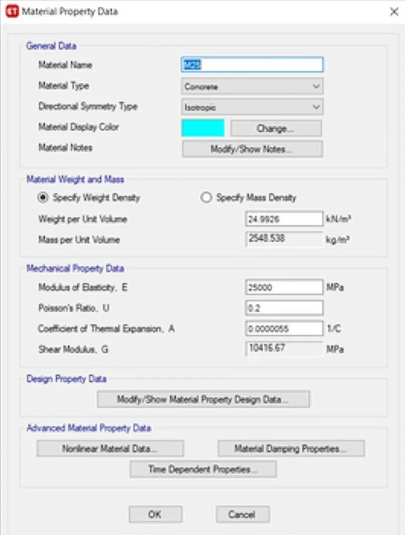
Go to add new material property option for M25 concrete
The properties of M25 as per IS code defined before gets displayed
STEP 4:
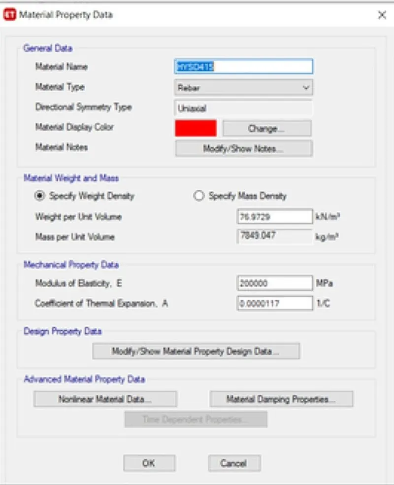
Now we need to add new material type as rebar and grade as HYSD Grade 415
Next we need to check the material property data as shown below
STEP 5:
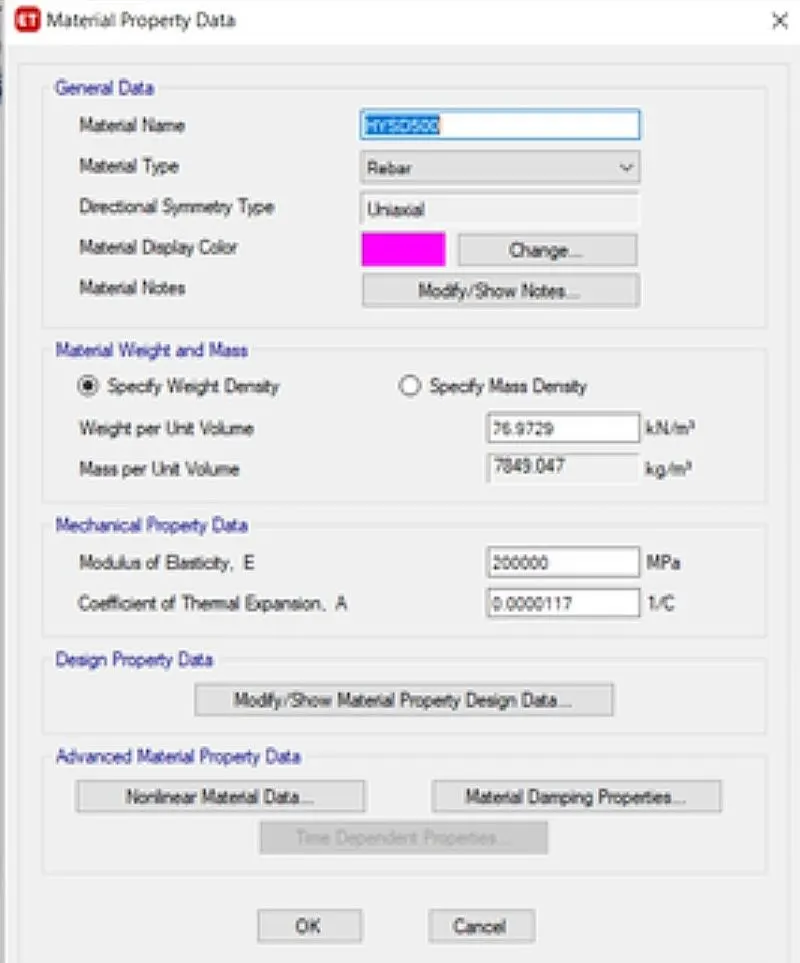
Now we need to add new material type as rebar and grade as HYSD Grade 500
Next we need to check the material property data as shown below
STEP 6:
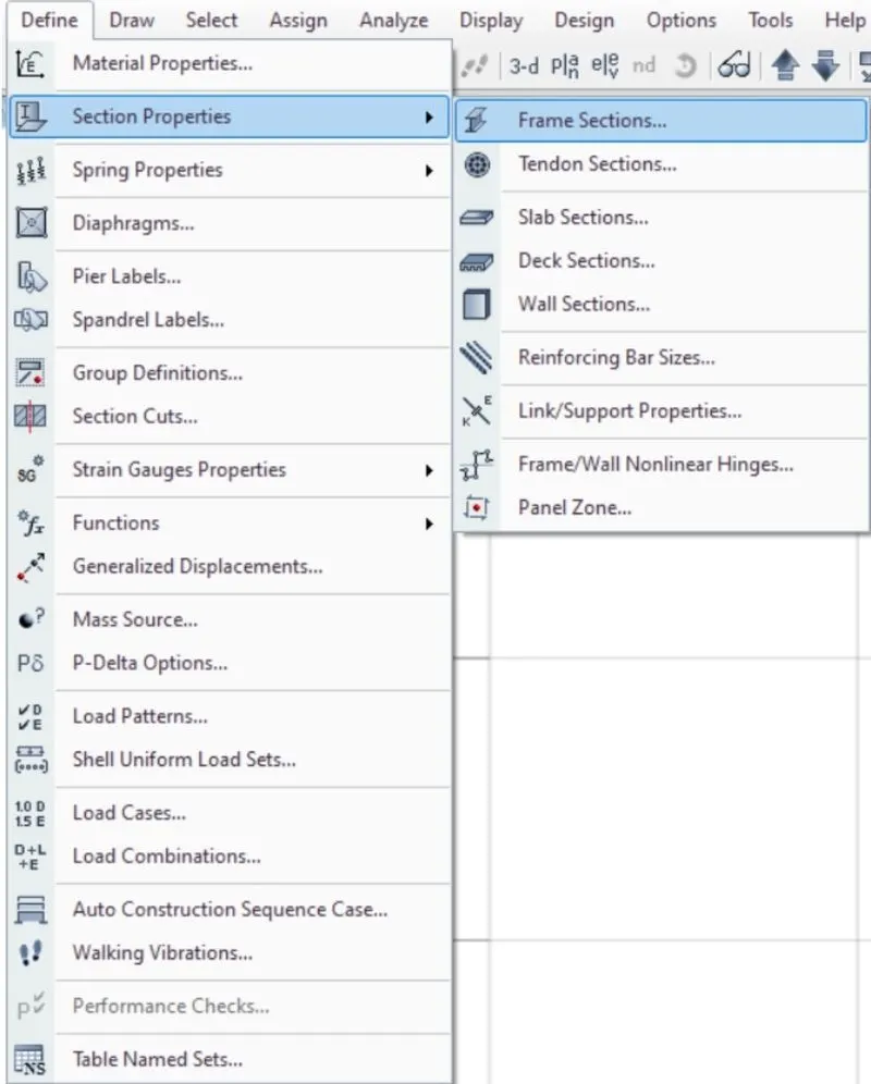
Now go to selection properties and click on frame sections
STEP 7:
After selecting the frame sections the new tab will appear in that we need to select the add new property as shown below
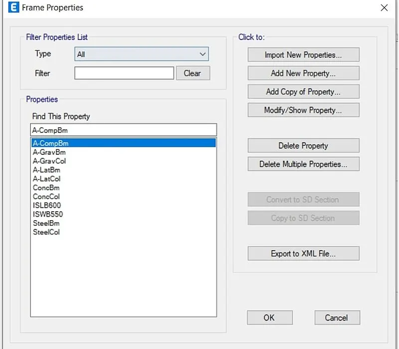
After selecting the add new property the new tab appears
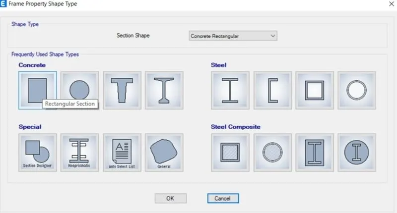
In that new tab we select the rectangular shape type in concrete as shown below
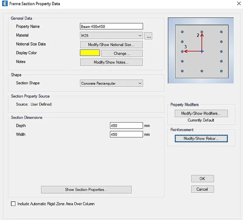
Next the frame section property data will be visible , in that we add a beam of size B450X450
Next we need to select the modify/show rebar option as shown
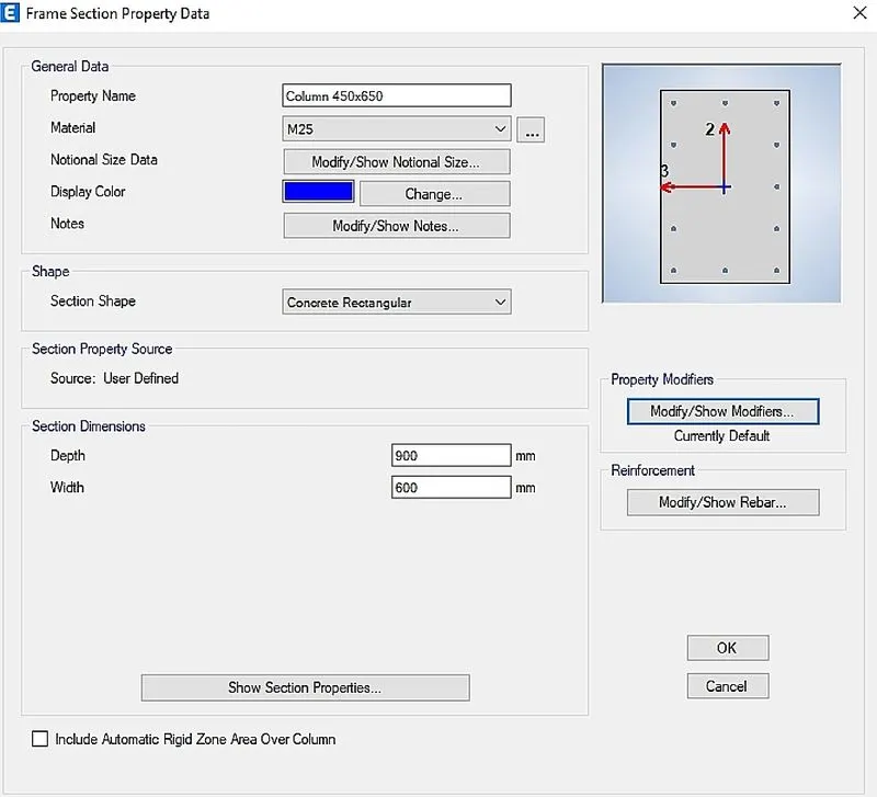
Now we have to add column size 450x650 in the frame section property data as shown
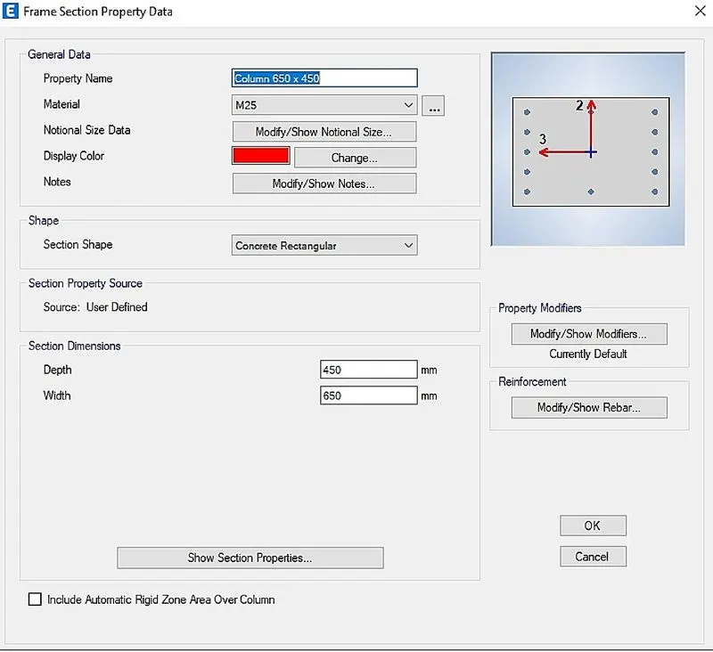
Now we have to add column size 650x450 in the frame section property data as shown
STEP 8:
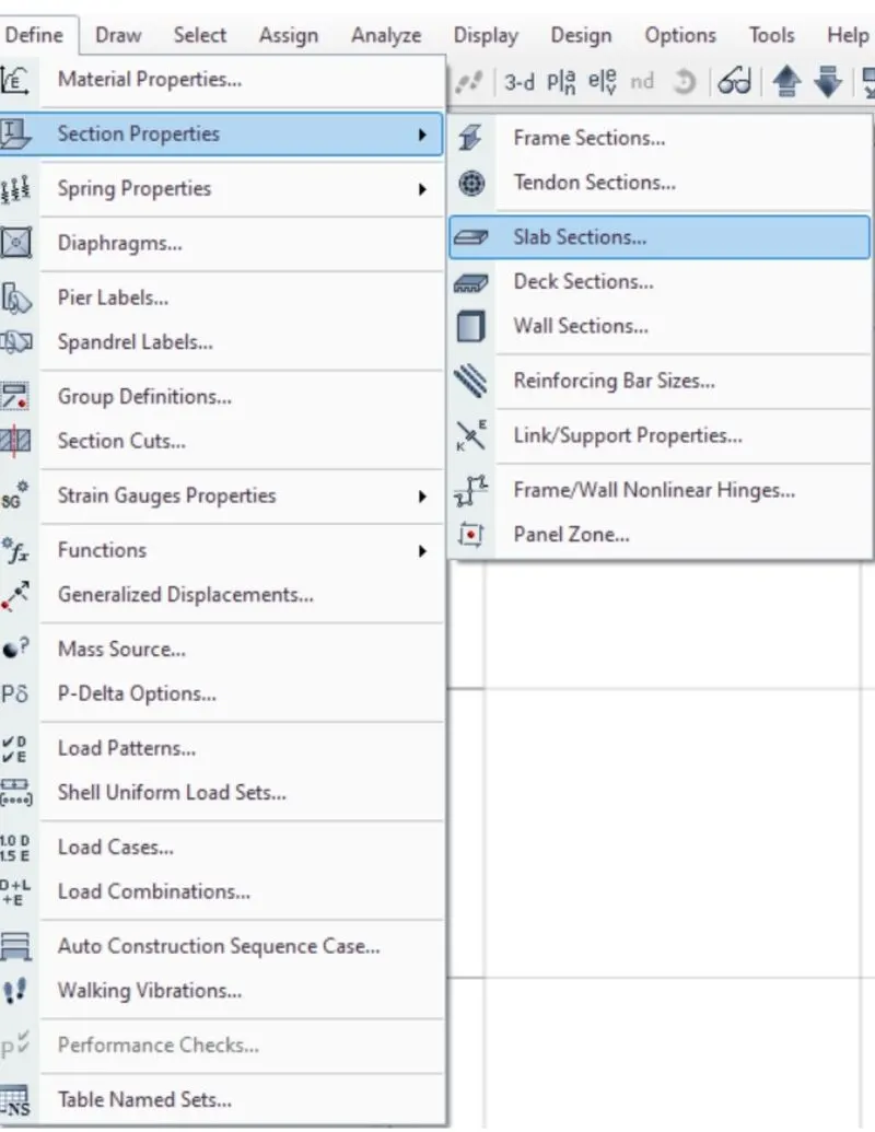
Next we select the slab option
Go to Define > Section properties > slab section
Next the slab properties will be visible.In that we select the Modify/show property option as shown below
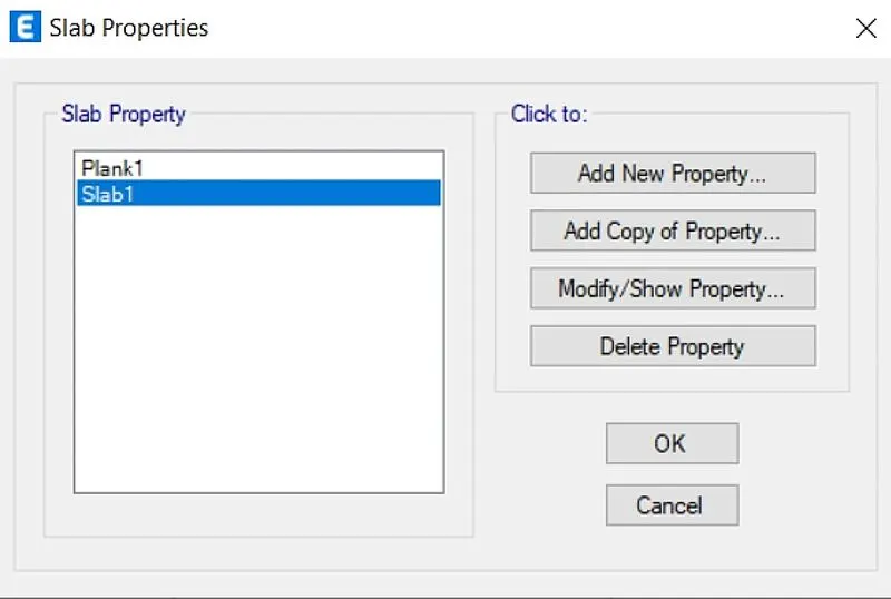
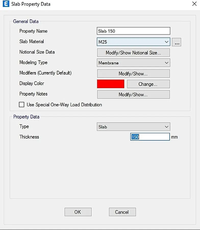
After selecting the option the new tab appears
In that we put the slab name as slab150 as the thickness of the slab is 150mm
We take the concrete grade as M25
Click OK
STEP 9:
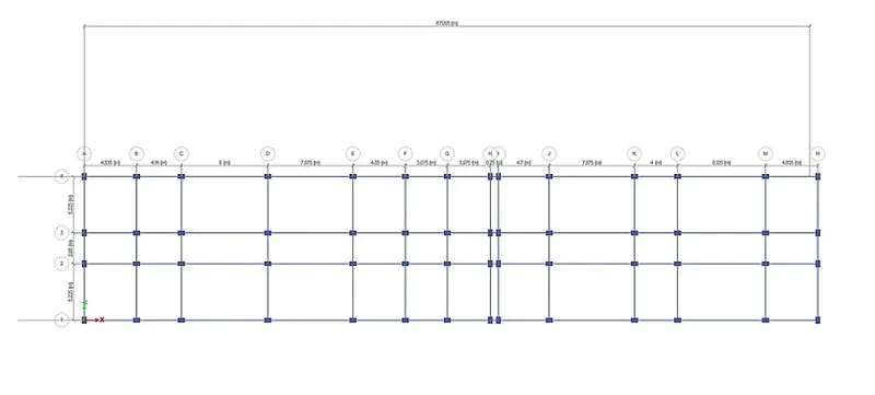
Next we need to add the columns and beams using the quick draw columns/beams option as shown below
STEP 10:
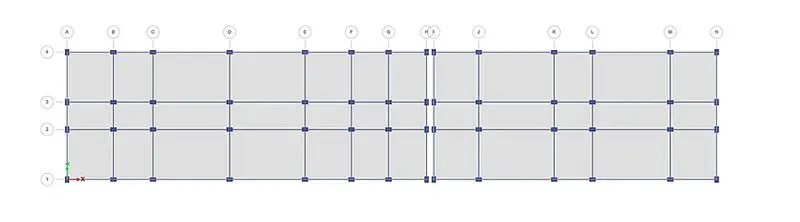
Apply the slabs in model using quick draw floor/walls option
STEP 11:
LOAD CASE:
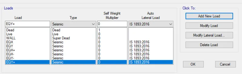
Now we add dead load, live load, seismic loads, wall load as shown below
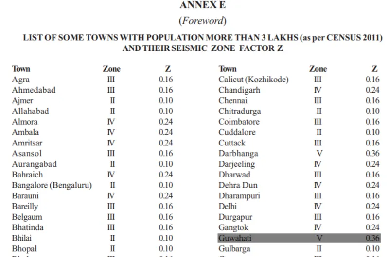
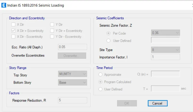
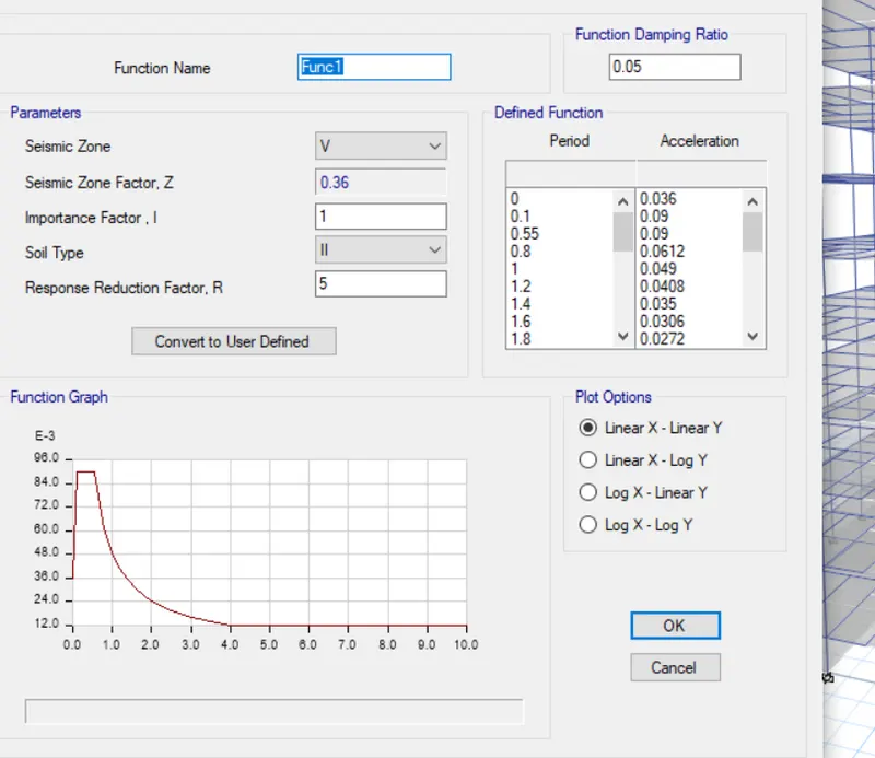
As per IS1893:2002, zone factor for guwahati,Assam is 0.36 and is in 5th zone
STEP 12:
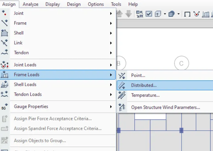
Next we need to select the distributed load from the frame loads as shown below
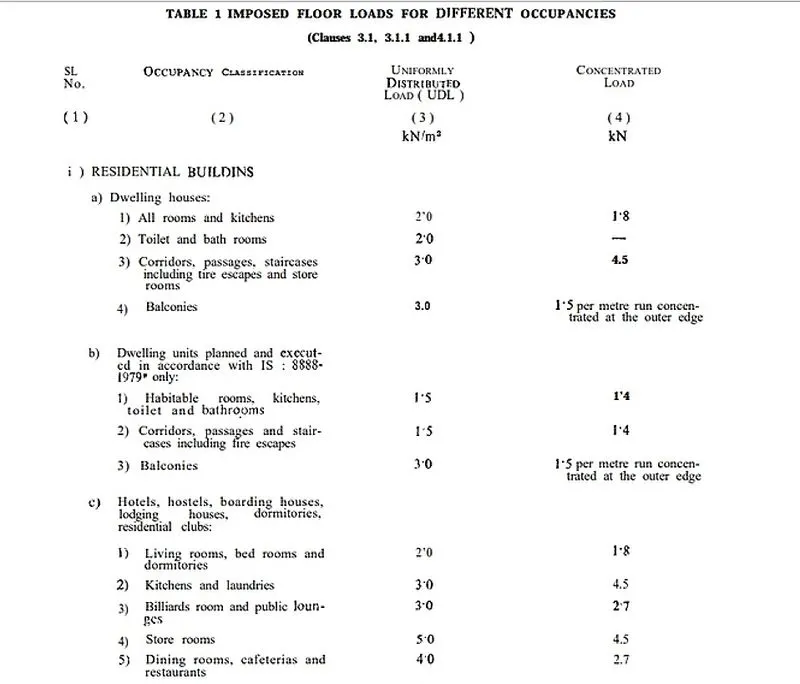
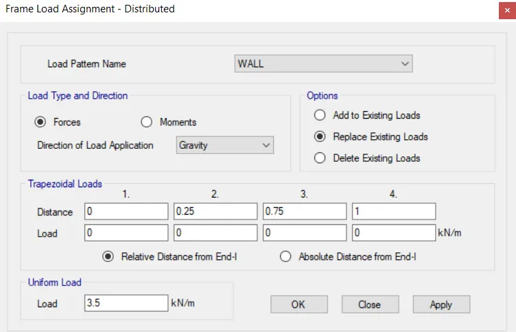
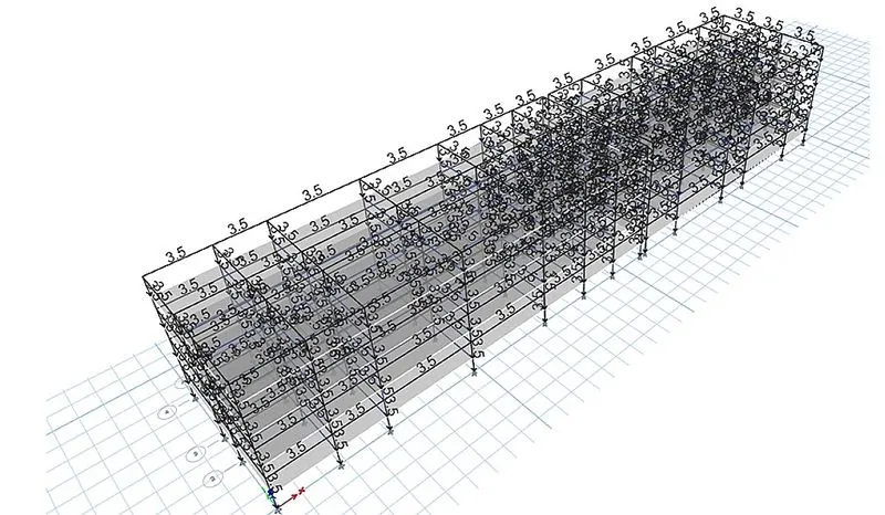
Then after the new tab appears in that we select load pattern as brick wall and we take uniform load as 3.5KN/m as per IS 875 PART2 and then click on apply and close
STEP 13:
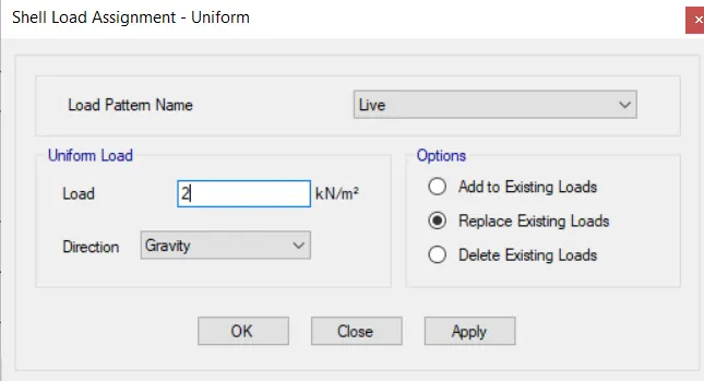
Next we have to click on assign option and then select shell loads from the shell loads we select the uniform load option as shown below
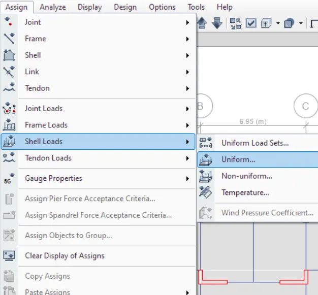
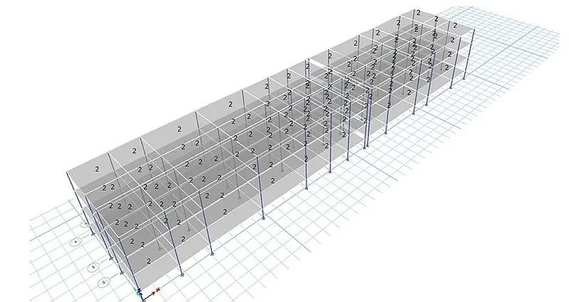
Next we apply 2KN/m2 as per IS 875 PART2 live load on the remaining area of the residential building
STEP 14:
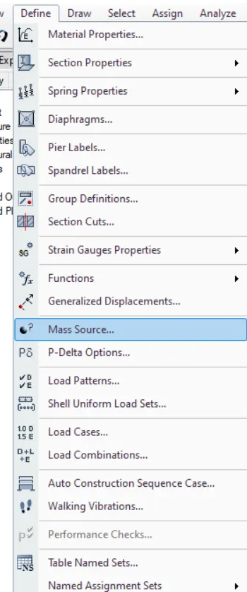
Next from the define option we select the mass source as shown below
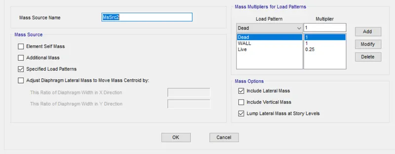
Next we add the load pattern in the mass source data as shown
STEP 15:
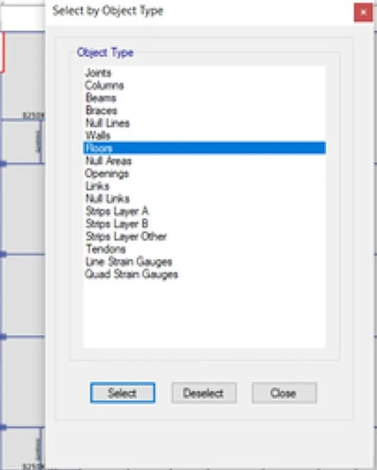
In the select option we select object type option as shown below
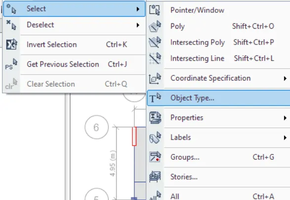
After selecting the object type option the new tab will be visible.In that select the floors and click on the select button and close
STEP 16:
After selecting the load combinations the new tab is visible , in that we assign "Add default design combos" option
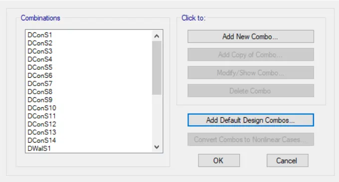
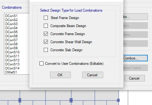
Next we select "concrete frame design" only as others arent needed in the add default design combinations as shown below
Now we can see here the load combinations are visible as shown below
STEP 17:
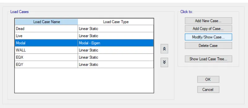
Next we select the modal cases from the define option as shown below
STEP 18:
Next we have to check the modal by clicking the check modal as shown
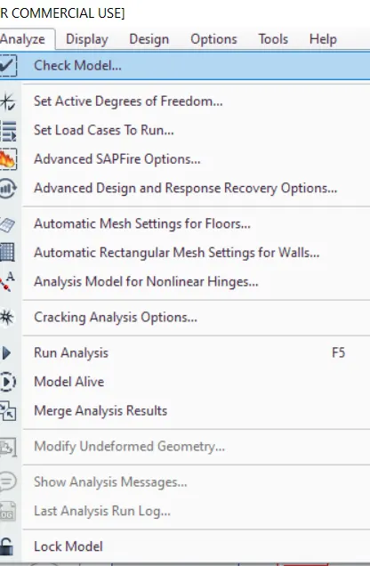
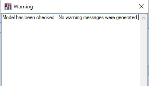
After the modal is checked the the warning tab wll appear and it tells that no warning message is shown
STEP 19:
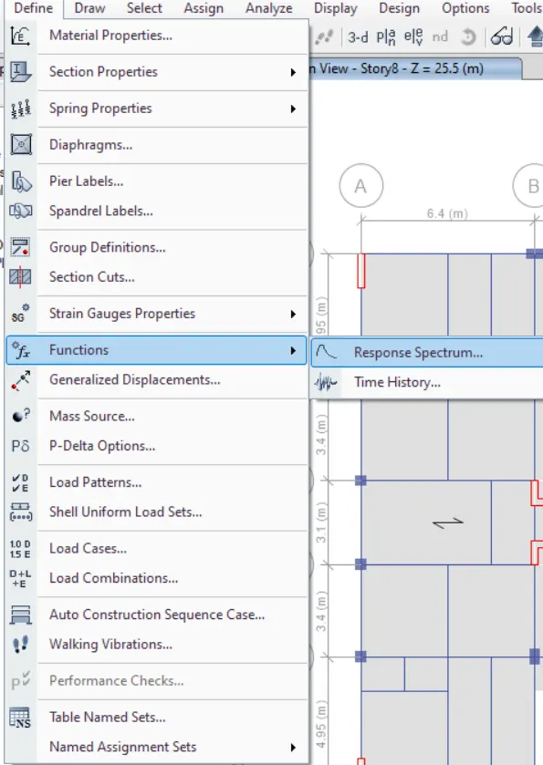
Now we select the resonse spectrum from the functions from define option, as shown below
After selecting the response spectrum the new tab is visible,In that we choose IS 1893:2016 from the "Choose function type" and click on the Modify /Show option as shown below
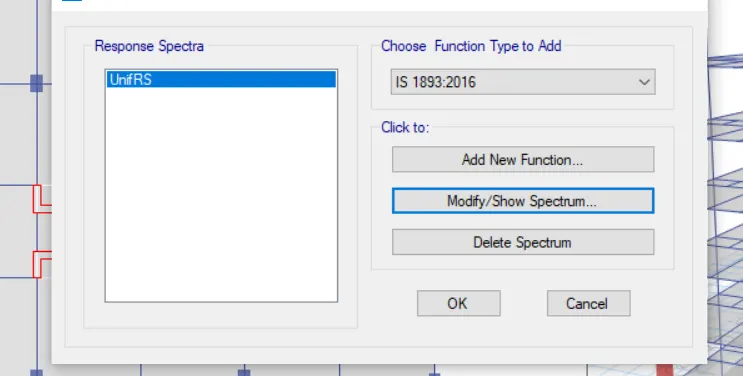
After selecting the modify/show spectrum option the new tab will appear.In that tab give the function name as IS FUNCTION and remaining details will be set by the software itself we dont need to set hem up.
STEP20:
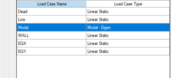
Next we have to select the load cases from the define option as shown below
Apply the loads on model
LIVE LOAD
STEP 21:
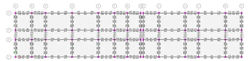
Run the analysis and take the `A_(st)`values for both beam and reinforcement
STEP 22:
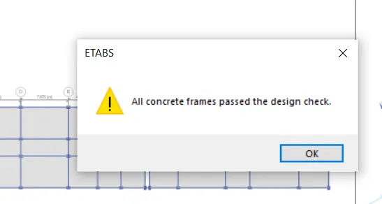
Check if all concrete frames pass the design check and then Export the SAFE file from etab model
STEP 23:
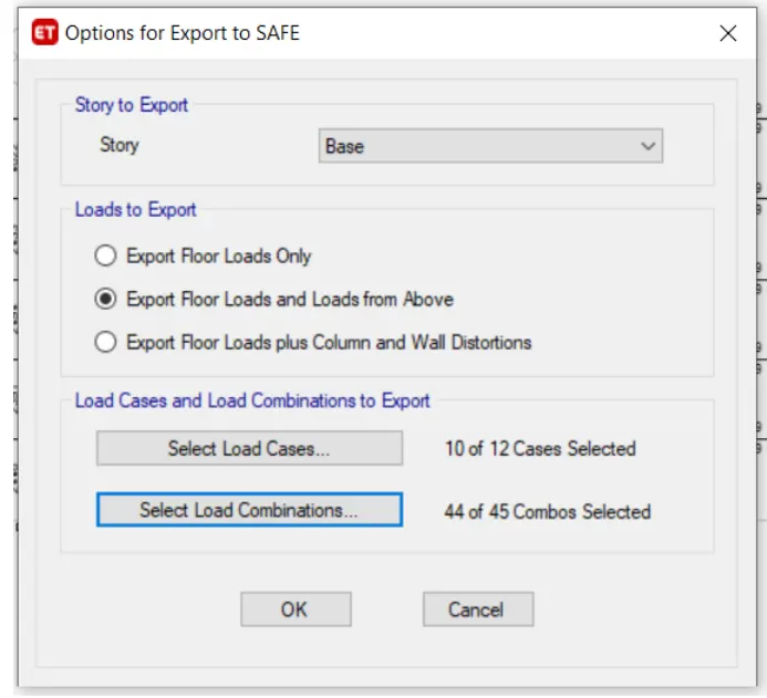
FILE>EXPORT>STORY AS SAFE V12.Fck
We have been given details in the question as follows:
Soil type=3
Piles of length= 10m
Pile dia = 500 mm dia
Load carrying capacity = 280kN
Pile cap-slab type-mat-500mm thick
Column cap-slab ty-stiff-500mm thick
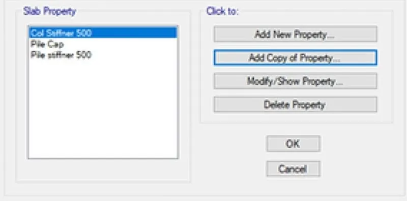
So firstly defining the slab property
STEP 24:
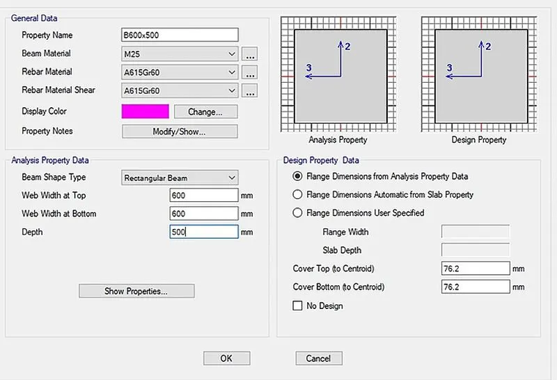
RC Beam section of tie connection of foundation is 600x500mm is assigned
STEP 25:
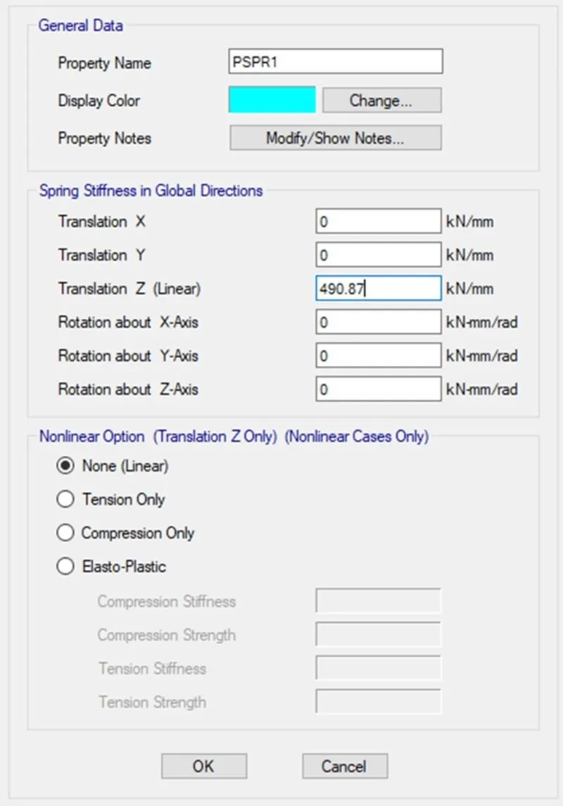
For piles the point springs are assigned , spring constant =EA/L
STEP 26:
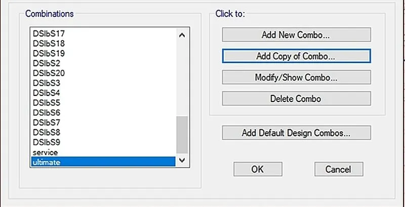
For bearing pressure checking the service load combination is considered
For flexural design the ultimate load combination is considered
STEP 27:
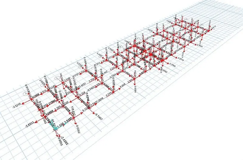
Loads imported from ETabs model is checked for the base support of the column
STEP 28:
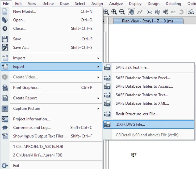
Export the modelling part into DXF file for drafting of pile details,since the drafting model takes time
STEP 29:
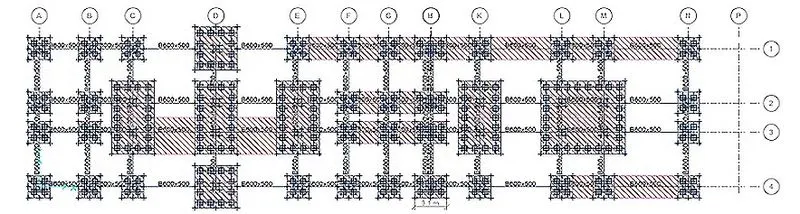
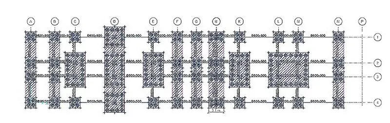
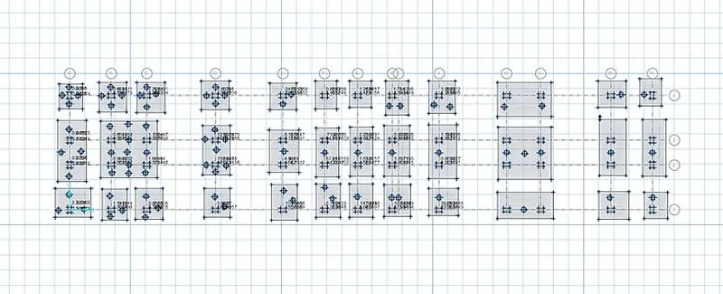
Design strips added in X direction and Y direction to review the strip result
X direction design strip
Y direction design strip
STEP 30:
Run the analysis
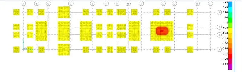
Some of the punching shear values are greater than 1
Need to increase the size size to rectify this error
STEP 31:
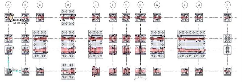
Top and bottom direction reinforcement result as per X direction:
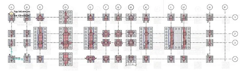
Top and bottom direction reinforcement result as per Y direction:
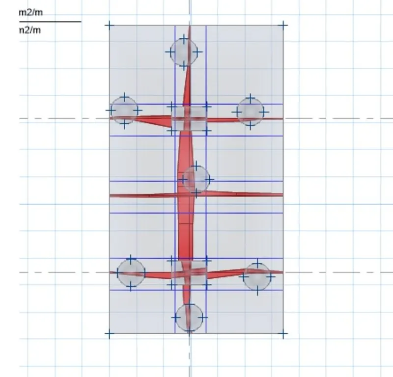
Showing the reinforcement details for one cap detail
RESULT:
The Design & Analysis of the project "Hostel building at Guwahati, Assam" is done sucessfully using ETabs and SAFE software
Also,the detailing drawing and reports are attached with the project