Project 2_Design & Analysis of a Hostel building at Guwahati, Assam
FINAL PROJECT
ANALYSIS AND DESIGN OF A HOSTEL BUILDING LOCATED IN GUWAHATI, ASSAM
INTRODUCTION:
Computational analysis and design of multistory buildings have become a lot easier with the use of modern software tools like ETABS. The software helps fasten the design process and assists from the very first phase of modeling till the detailing process. At the same time, the accuracy and precision achieved through these computational tools are unmatched. However, you must know the manual concepts that run behind any building analysis model. So, the right conceptual knowledge in addition to hands-on tool experience is what is needed to execute any project successfully from start to end. And this is what is done in this project. A 3-story hostel building has been modeled, analyzed, designed, and detailed to send the good for construction drawings at the site.
TOOLS USED:
- ETABS: For modeling, analysis, and design of the superstructure.
- SAFE: For modeling, analysis, and design of the foundation.
- AutoCAD: For reinforcement detailing and producing good for construction drawings to be sent to the site.
DETAILED PROCEDURE:
This project has been divided into three major phases that are:
- Analysis and Design of Superstructure using ETABS for Seismic Force.
- Reinforcement detailing of the concrete frame using AutoCAD.
- Foundation Design Using SAFE.
So, the complete stepwise procedure to carry out each of the above project activities is discussed in detail in the following sections.
1. Analysis and Design of Superstructure using ETABS for Seismic Force.
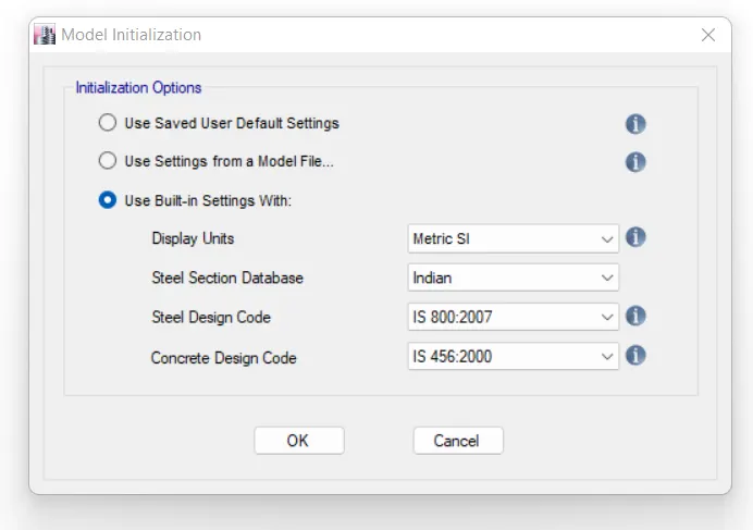
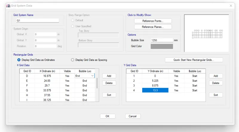
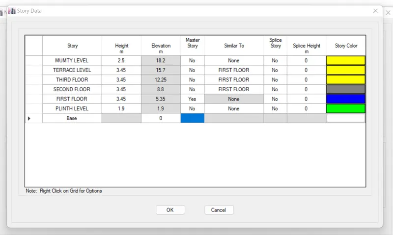
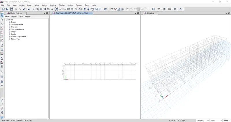
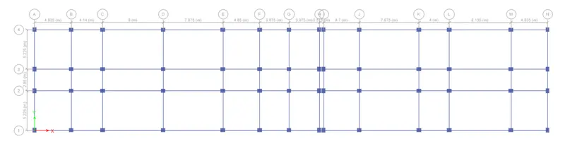
- Open Up New Model and Set Grid and Story Data as per the Architectural Drawings Received
- Whenever you design a building, you will always be provided with the Architectural model specifying the desired column size, position, and orientation within the building limits.
- So, at first, we can initiate the building model with this primary data if it is feasible from the structural point of view as well.
- And if not, we need to discuss the issue with the Architect and try and work out an alternate framing plan as per the structural need.
- However, in our case, the framing plan provided by the Architect seems fine to start with.
- So, once it is done, we can start modeling the building using ETABS.
- The process is fairly simple and has already been discussed repeatedly in previous assignments.
New ETABS Model with Custom Grid and Story Data
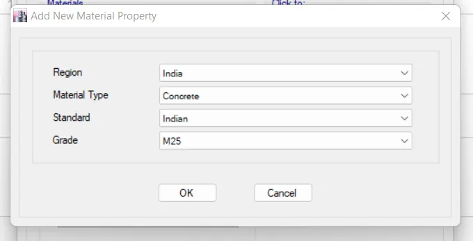
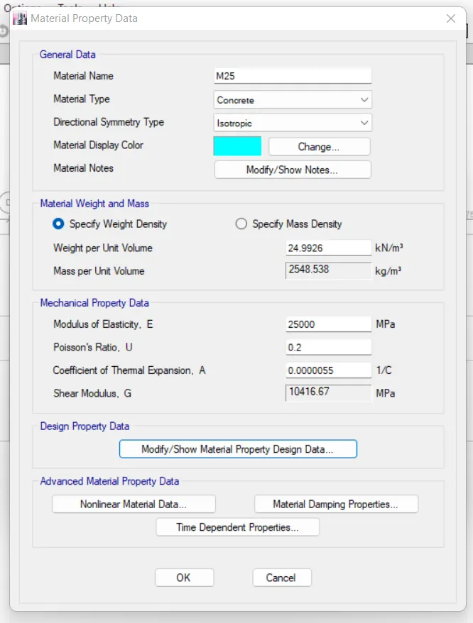
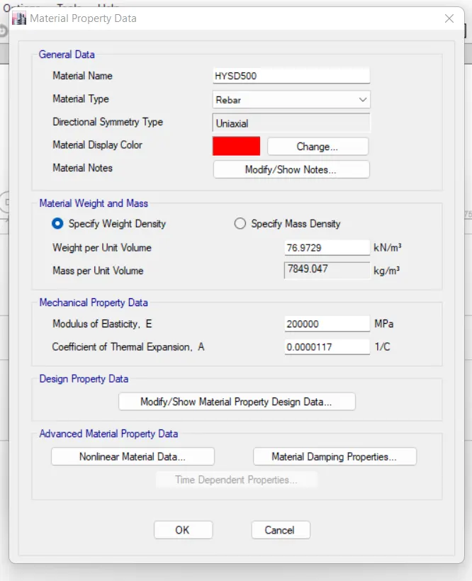
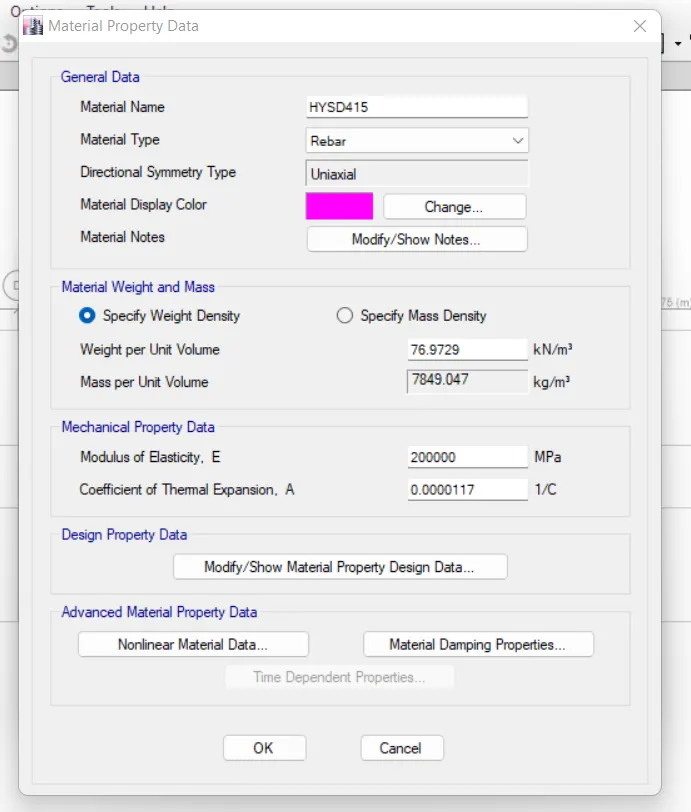
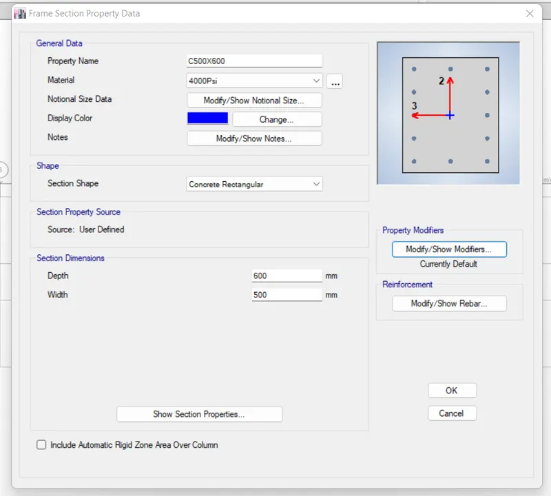
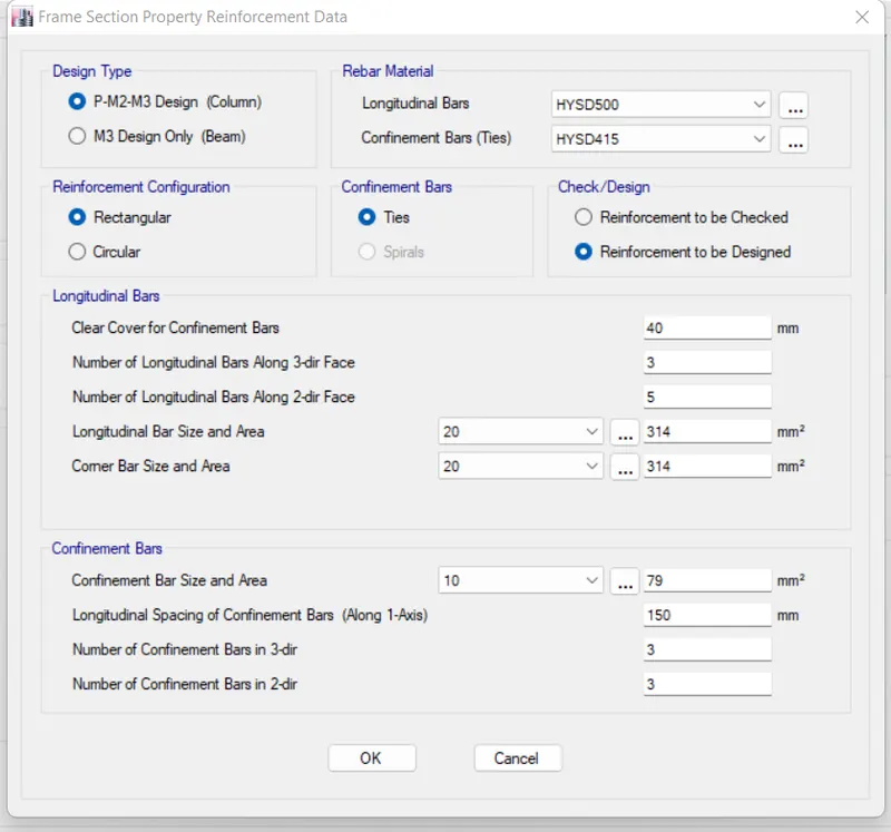
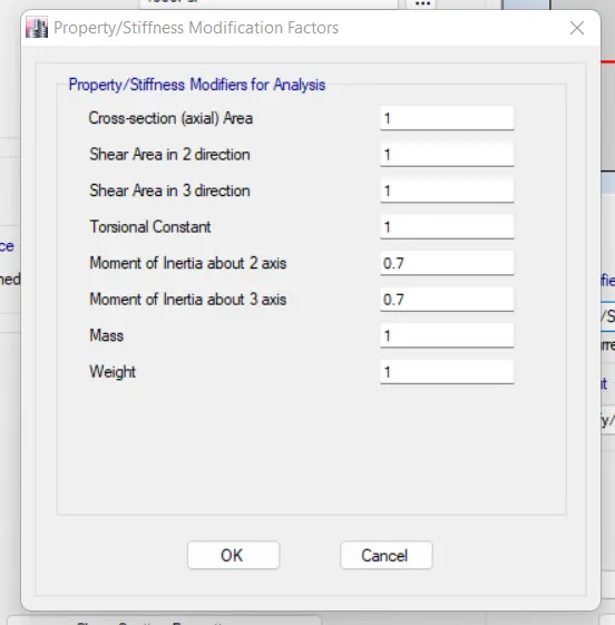
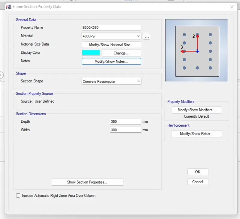
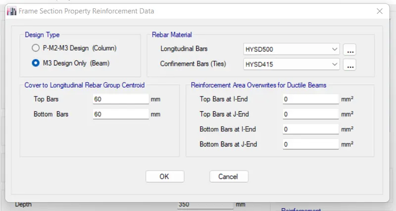
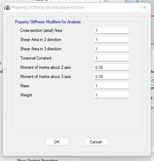
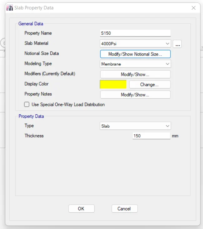
- Define Material and Section Properties
M25
HYSD 500
HYSD 450
C500X600
B300X350
SLAB 150mm Thick
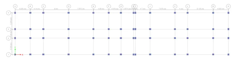
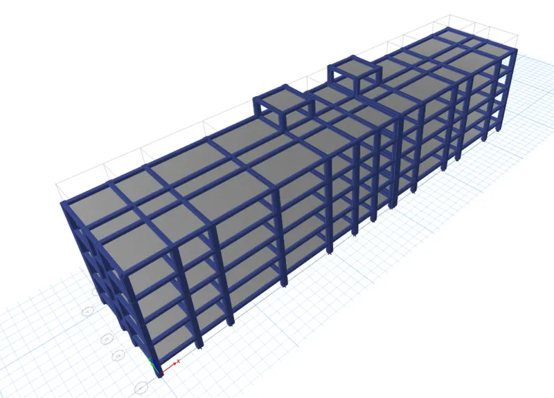
- Start Modeling by Drawing Structural Elements
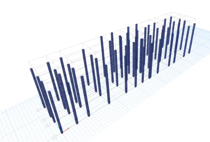
Quick Draw Columns
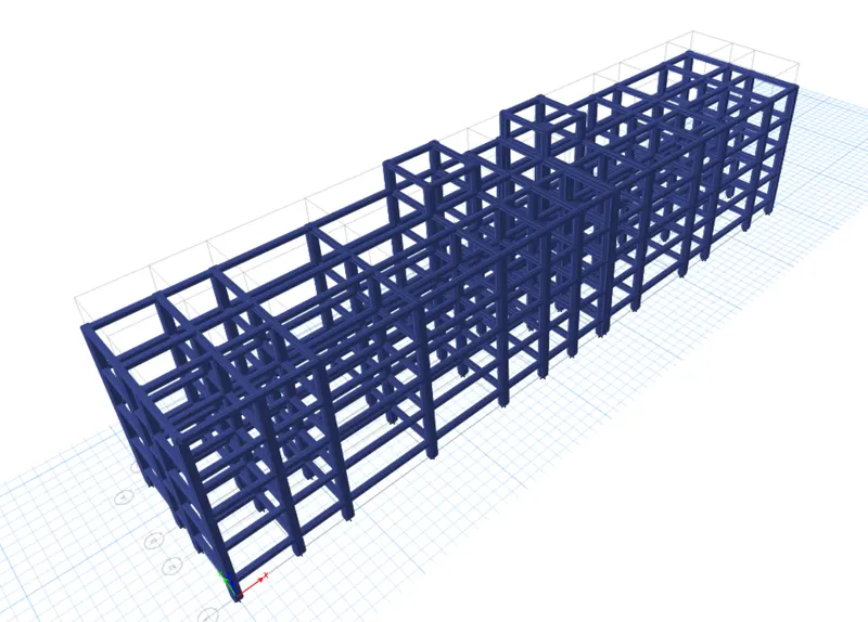
Quick Draw Beams
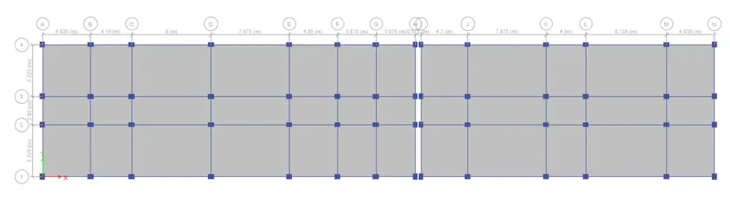
Quick Draw Floors
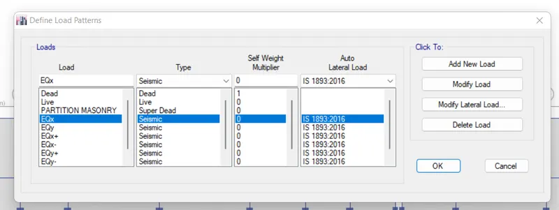
- Define and Assign Load Patterns
Load Patterns
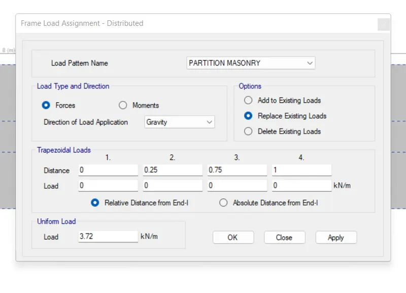
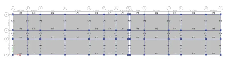
AAC Block Load Assign
AAC Load for Terrace
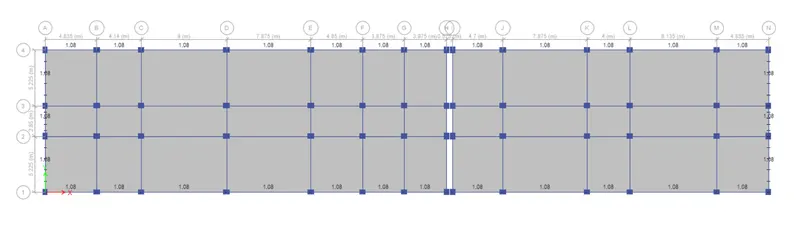
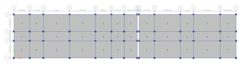
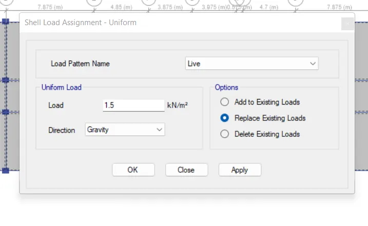
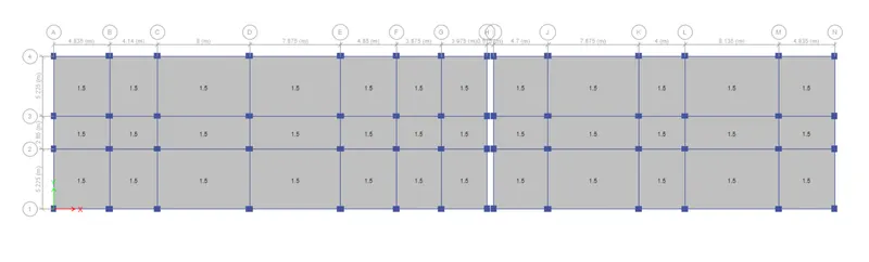
Live Load Assign (For All Rooms)
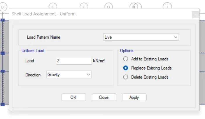
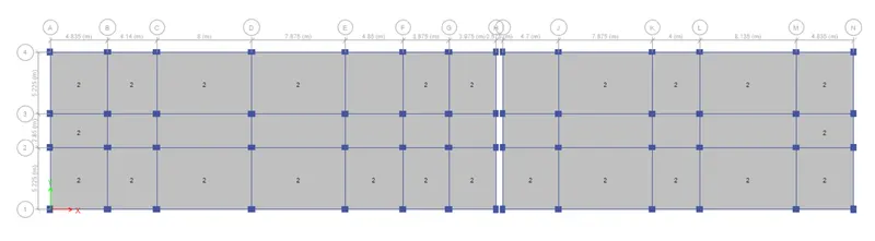
For Corridor and Staircase
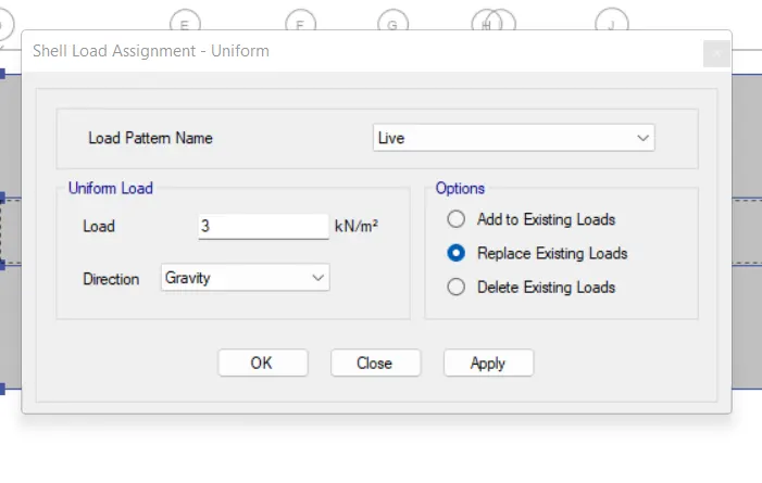
For Terrace
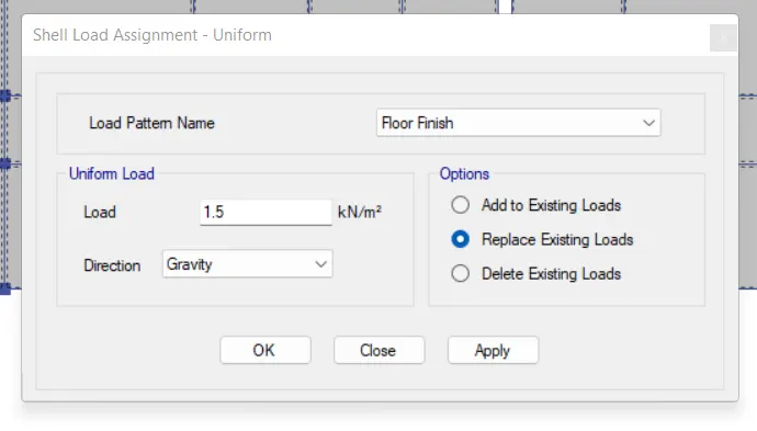
Floor Finish Load
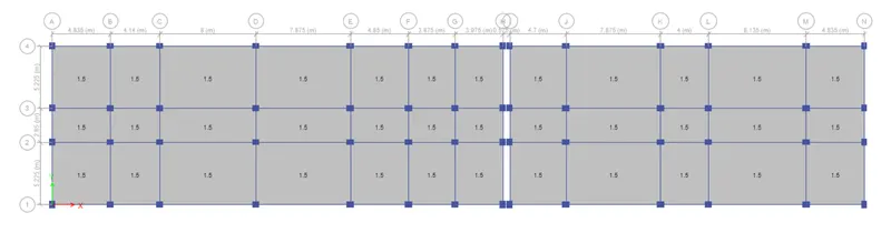
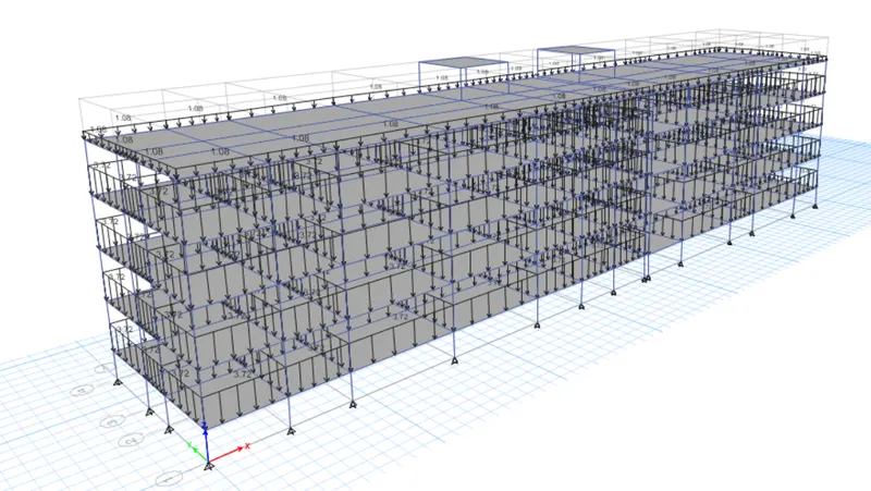
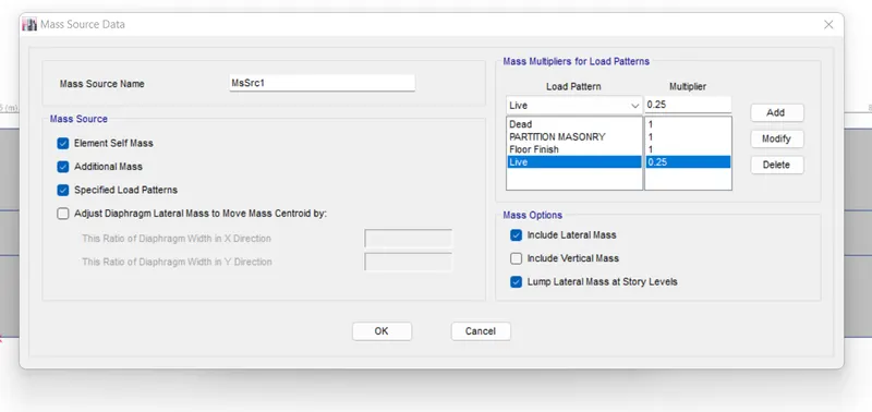
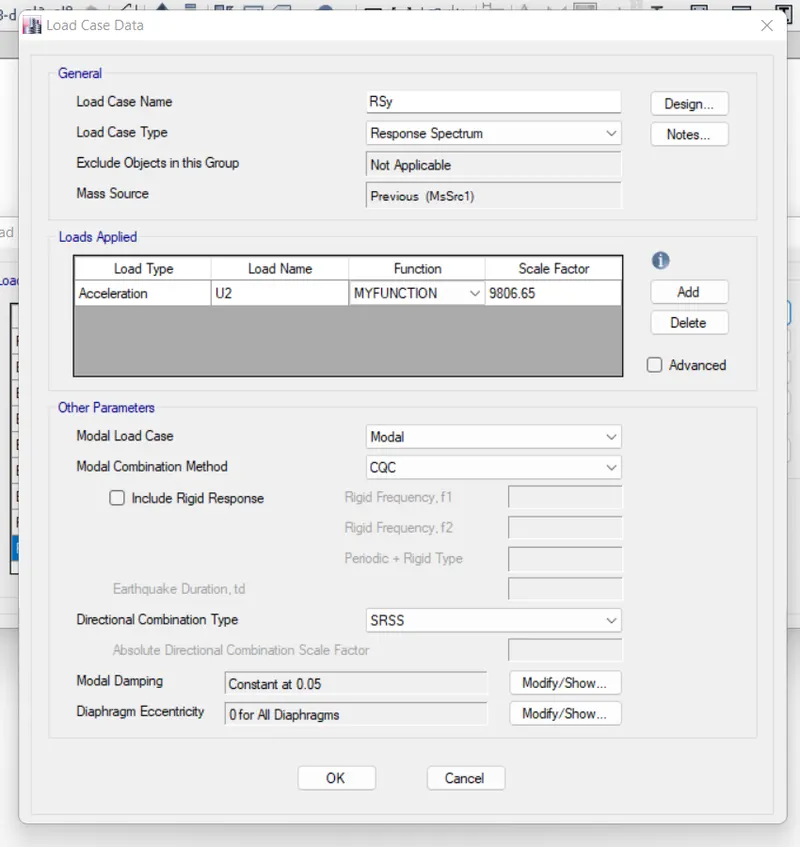
- Define Mass Source, Modal Case, and Response Spectrum Function
Mass Source
Moal Case
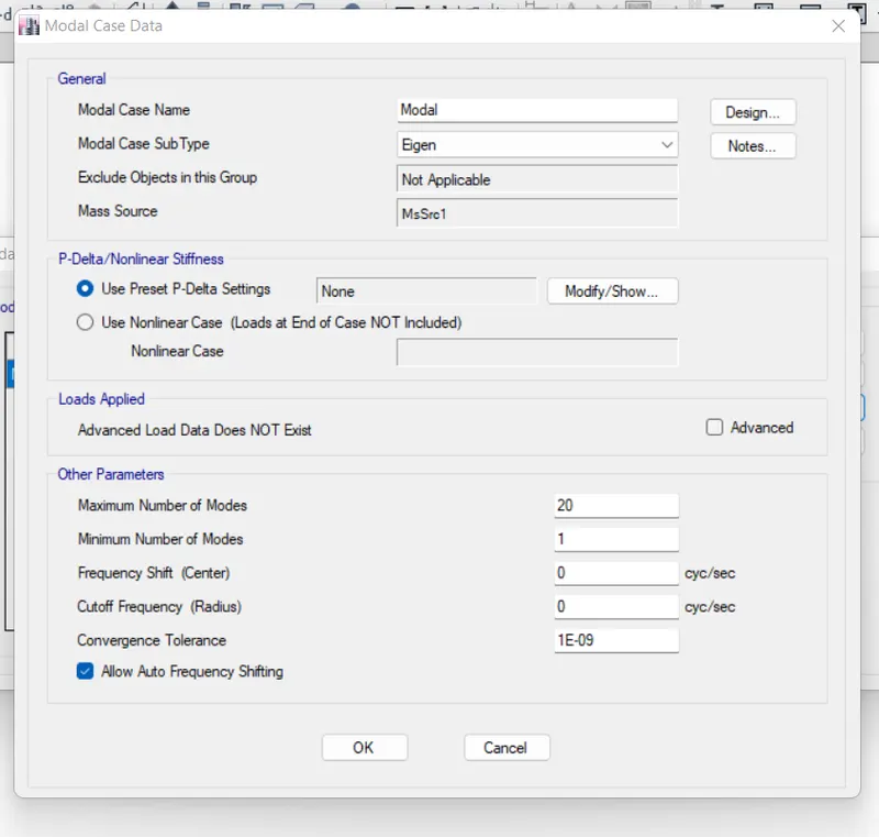
Response Spectrum Function
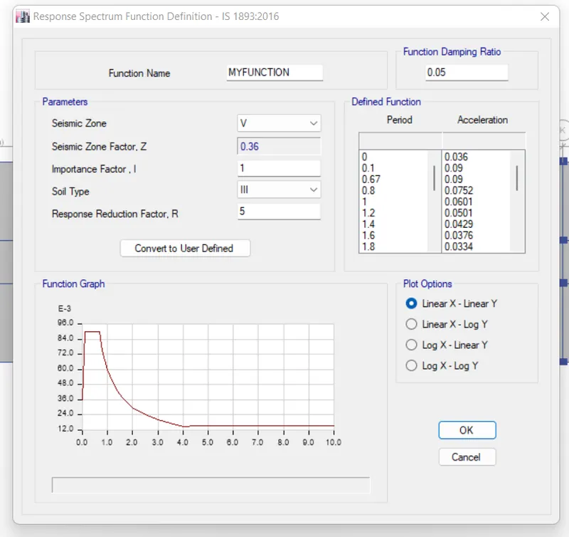
RSx
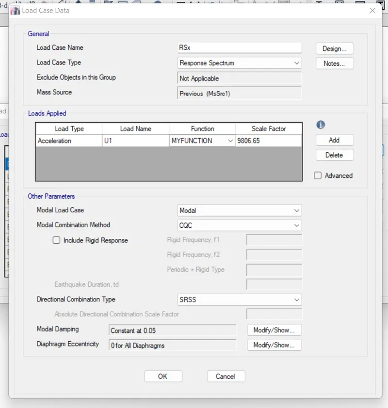
RSy
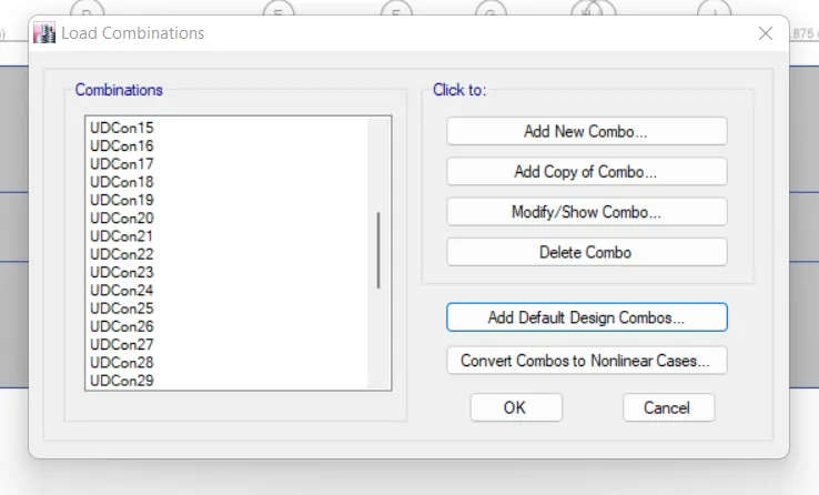
- Generate Load Combinations
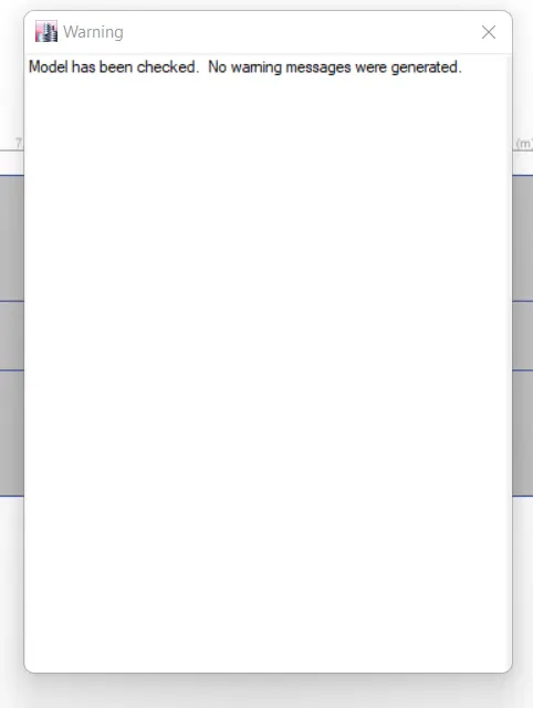
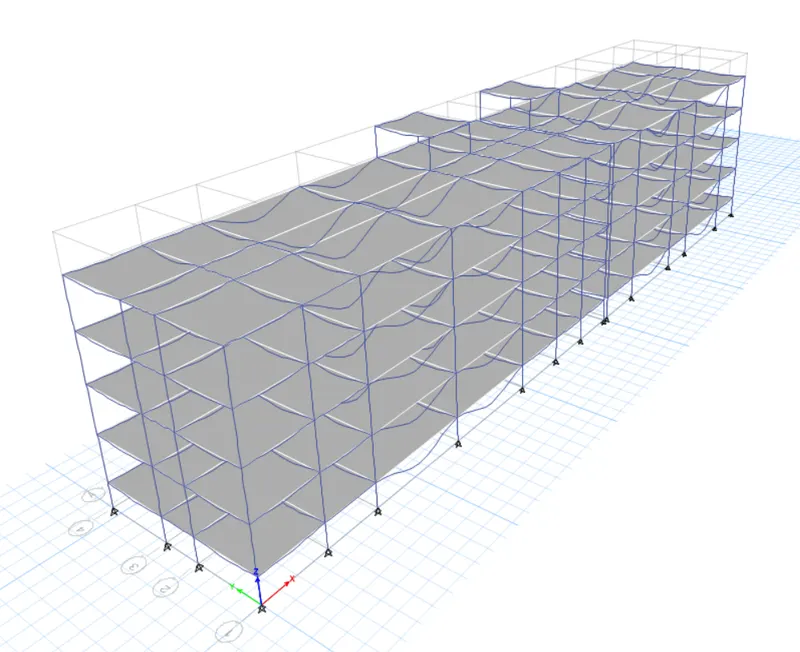
- Check The Model and Run the Analysis
- Conduct the Structural Output Checks
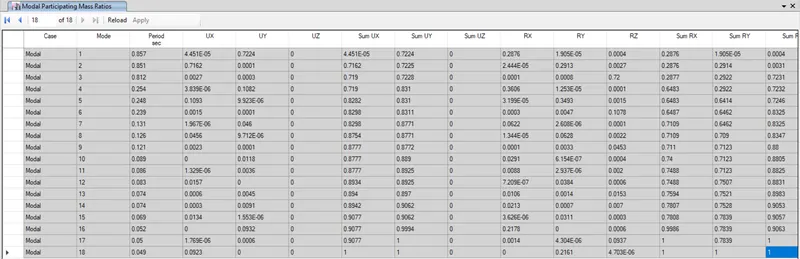
Modal Response Check
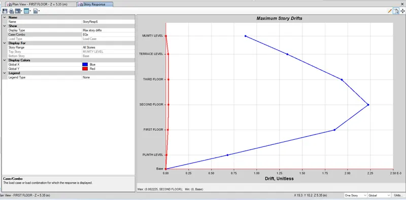
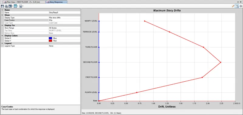
Story Drift Check
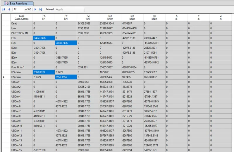
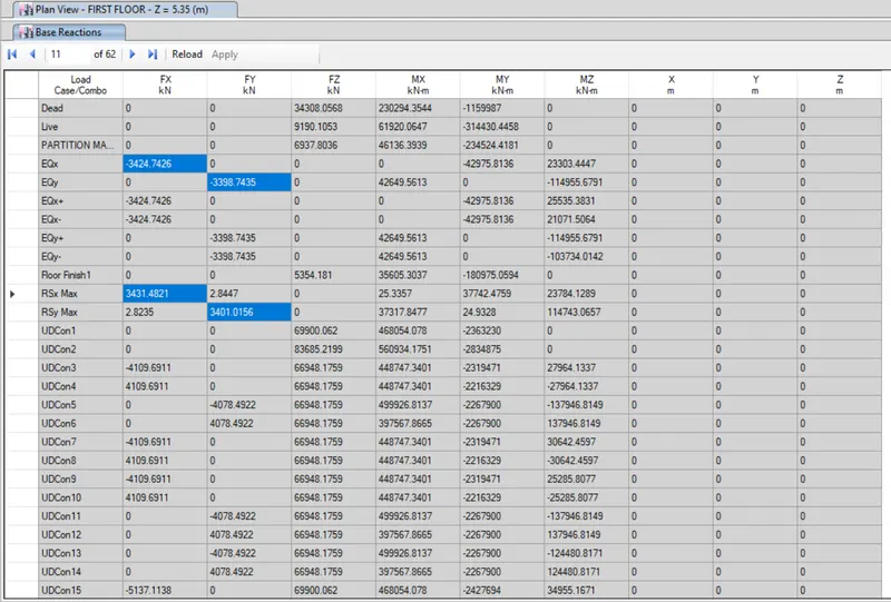
- Base Shear Scaling
Difference in the base shear
Scale Factor Multiplication
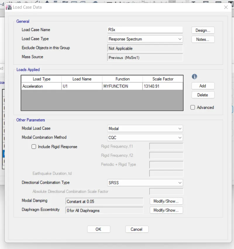
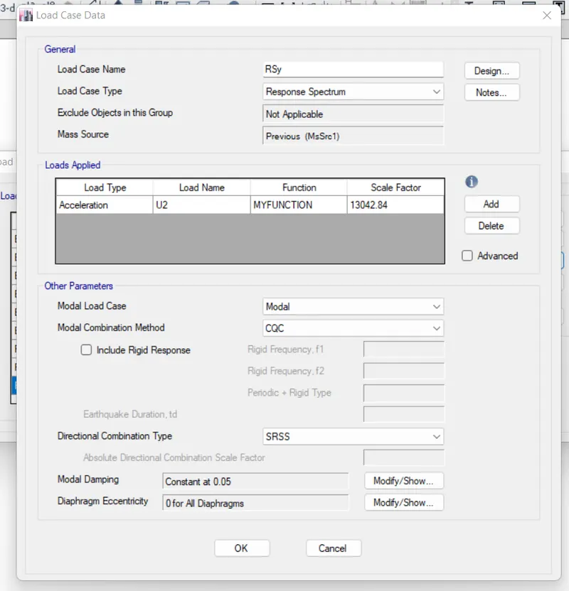
Equal Base Shear
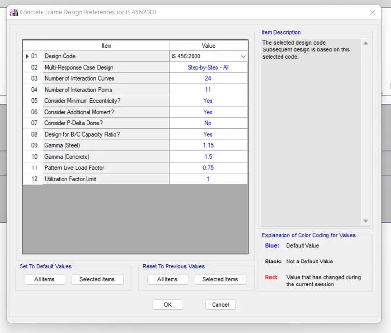
- Run the Design
View/Revise Design References
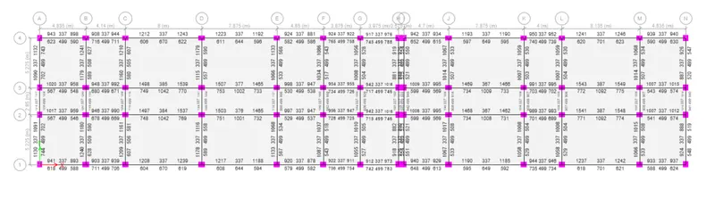
Design Completed
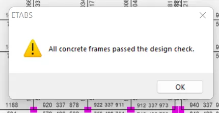
Verify all Members Passed
2. Reinforcement detailing of the concrete frame using AutoCAD.
- Max Steel as per ETABS Results
Beam B34 Longitudinal Steel Requirements

B34 Shear Steel Requirements

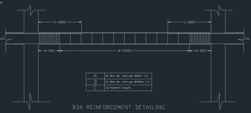
B34 Reinforcement Detailing as per IS-13920
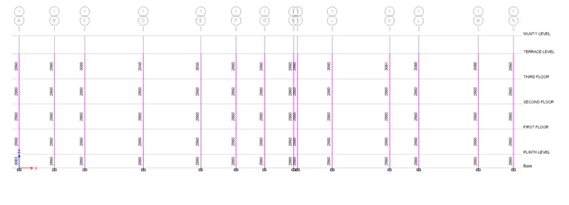
Column C29 Longitudinal Steel Requirements
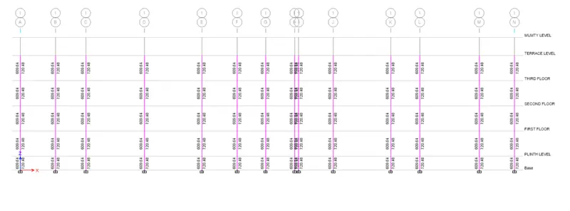
C29 Shear Requirements
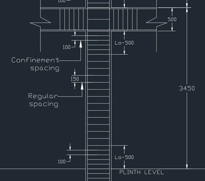
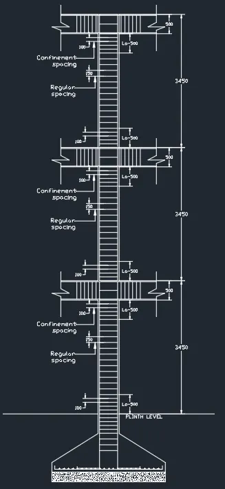
C29 Reinforcement Detailing As per the IS-13920
3. Foundation Design Using SAFE
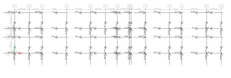
- Export Base Reactions from ETABS to SAFE
Open Base Level Plan in ETABS
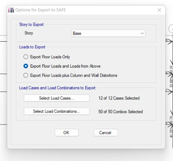
Go to File>Export>F2k File for SAFE
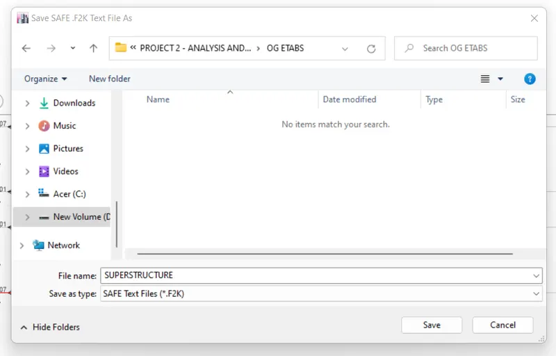
Save at the Desired Location on your Machine
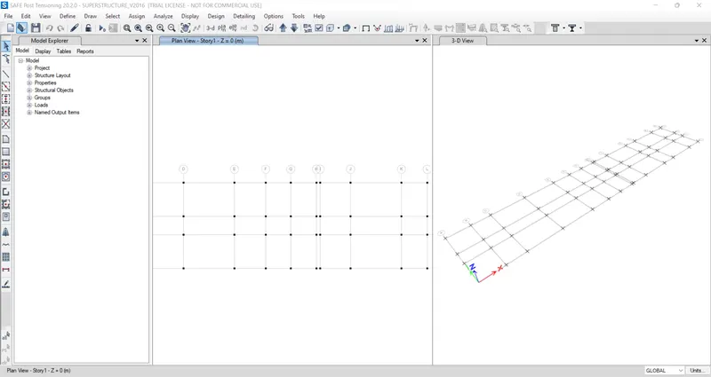
- Open SAFE and Import the Same File
Open safe>files>import>f2k file>Select model>OK
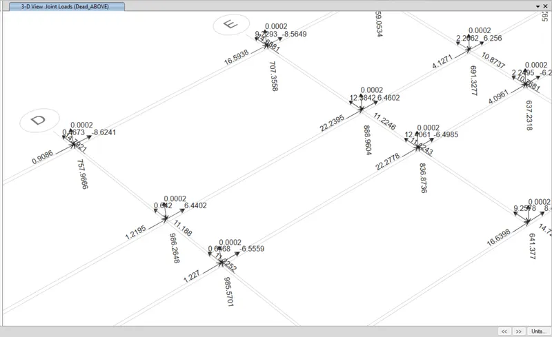
All the Loads Imported and Assigned Already While Importing
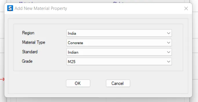
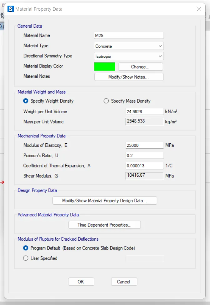
- Define Material and Section Properties
M25
HYSD 500
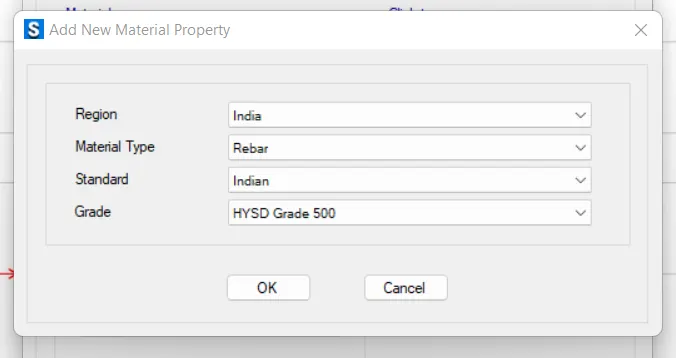
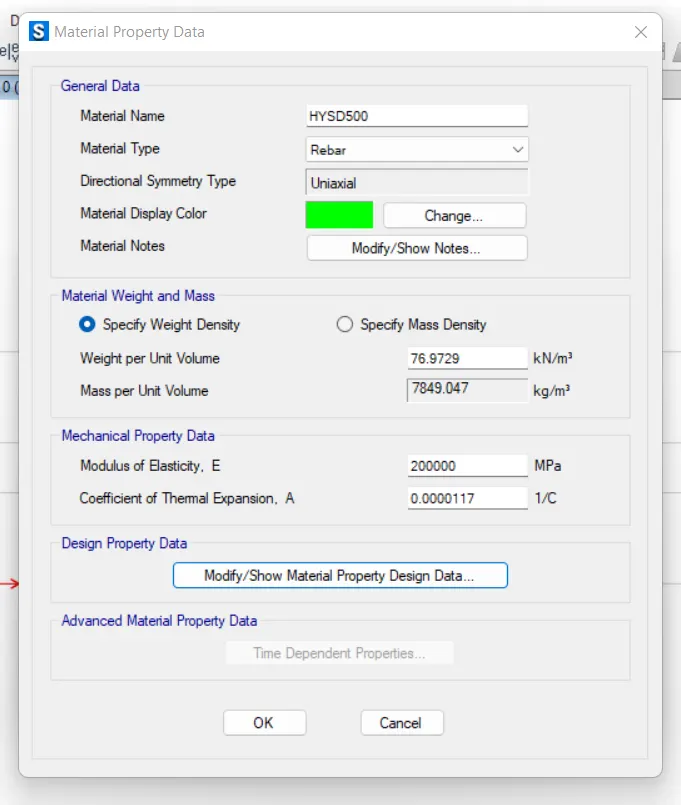
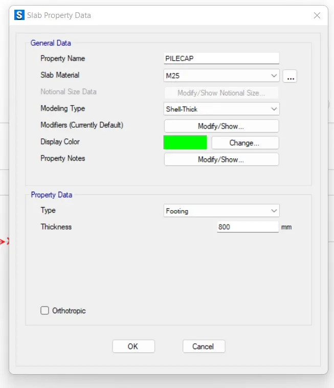
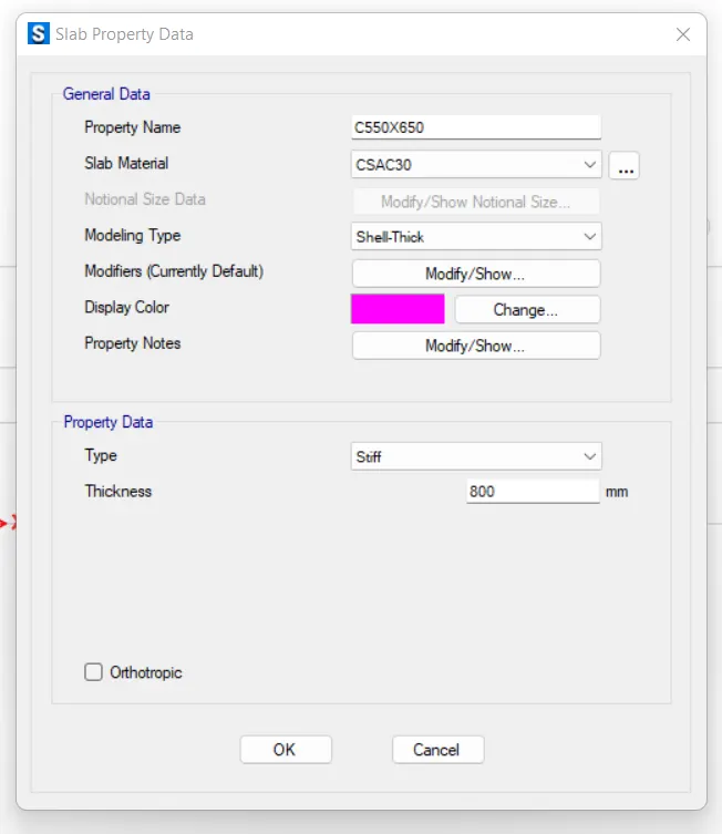
PileCAP
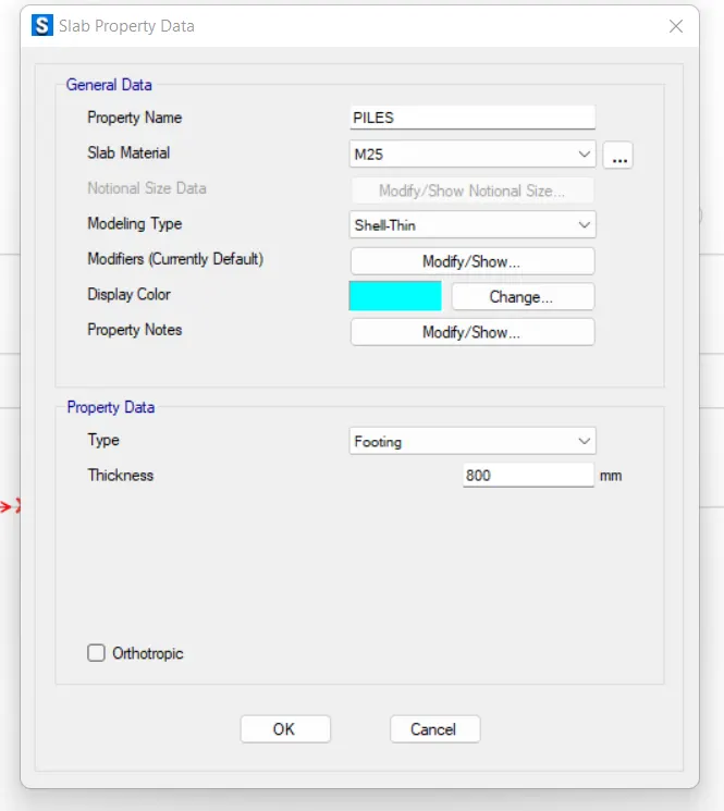
500mm dia. Piles
Stiff Column Section
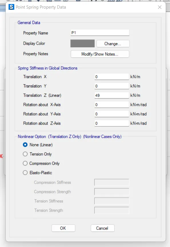
Define Point Spring
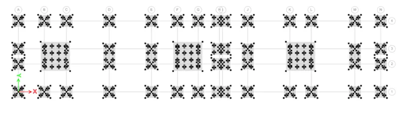
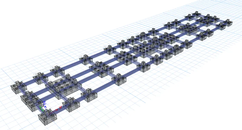
- Draw the Pile Foundation Layout Using Draw Tool in SAFE
NOTE: Detailed explanation on how to execute the drawing has already been given in previous assignments. Hence, the same is not repeated here and rather the final output has been inserted below:
- Run the Analysis and Design and Conduct the needed Checks for the Same
Click on the play button to run the design and analysis of the pile foundation model. All the required checks are inserted below:
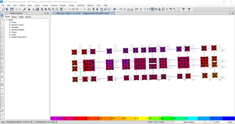
Check for Settlement
A total settlement of 25mm is allowed for pile caps. However, you can see in the below image that the displacement for our design does not even cross 8mm for the SLS load combination. Hence OK.
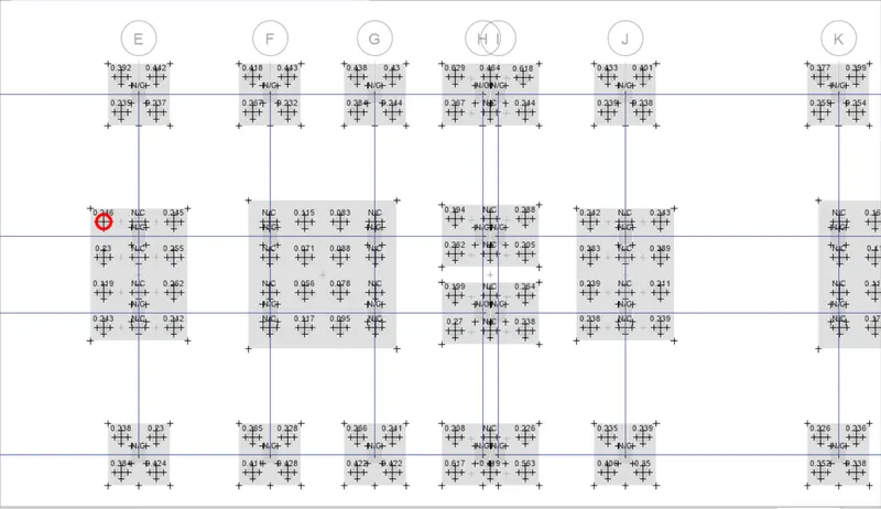
Check for Punching Shear
The punching shear ratio should not cross-unit value which in our case, it doesn't, Hence OK.
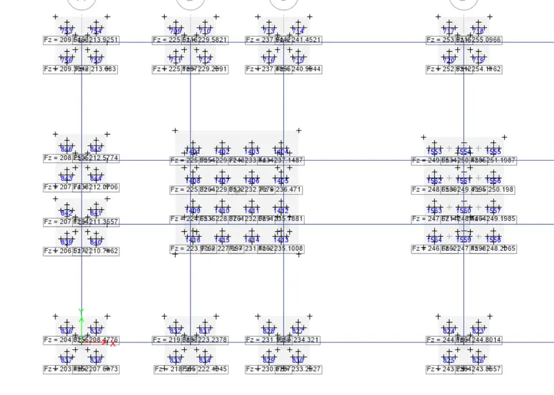
Check for Base Reaction of Piles
The reaction induced in piles must not cross the net bearing capacity of the piles used which in our case is 280KN. And the reactions induced in piles are less than 280 as shown below. Hence, OK
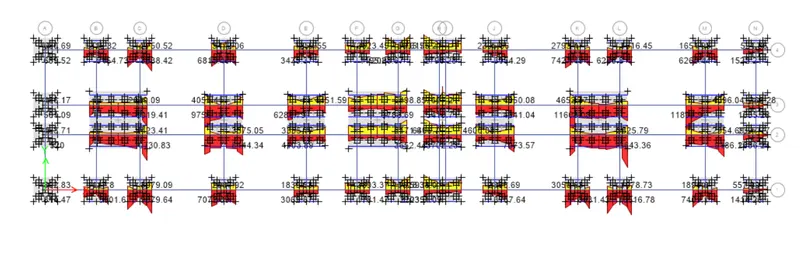
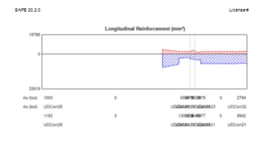
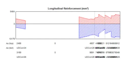
Steel Requirements
CONCLUSION:
Thus, the entire design process for buildings can be completed precisely with the help of the latest computational tools like ETABS when you know how to use them and not to mention, you also have the conceptual clarity regarding the building design calculations.