Project 2_Design & Analysis of a Hostel building at Guwahati, Assam
AIM:- to analyse and design the structure using etabs for the architechtural plan of G+3 hostel building provided which is situated in assam and also design the foundation details using safe
GIVEN DATA:-
- achitechtural plan of the building
- elevation section view of the building
- walls are constructed with AAC blocks
- ground level is 2m above the existing ground level
- grade of the concrete is used as M25
- grade of the steel for main reinforcement is Fe500
- Grade of the steel for shear, confinement reinforcement is Fe415
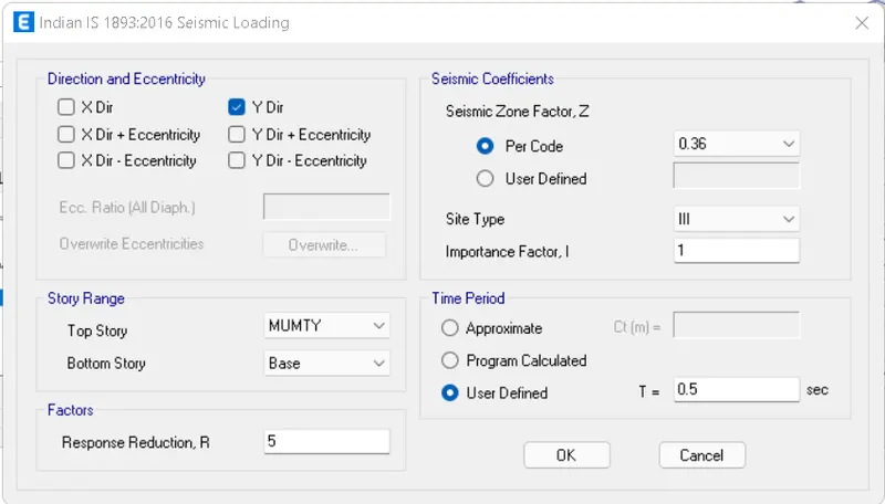
- location of the building is given as guwahati which comes under ZONE 5 with a seismic zone factor of 0.36
- assume any data required as per the IScodes
ETABS MODELINGS
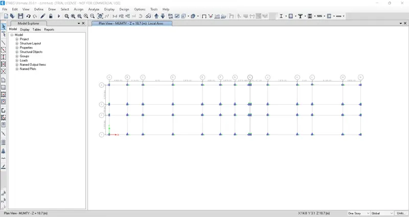
To create grids and story following the architechtural plan
- open etabs
- go to new model
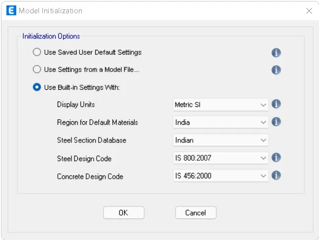
- select the codes for concrete and steel
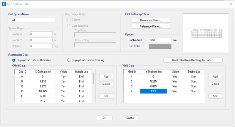
- then click on custom grid data
- add and edit the grids along X and Y diection
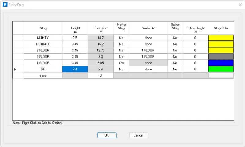
- then click on custom story data
- add the no of storey and specify the height of each storey as per the elevation view
- then click on ok
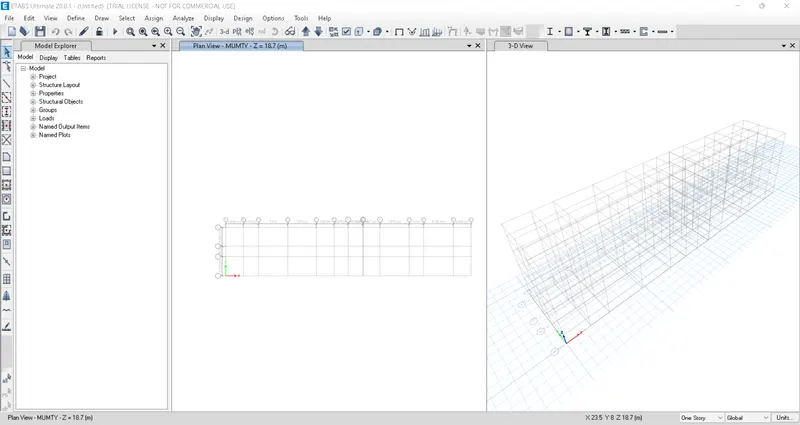
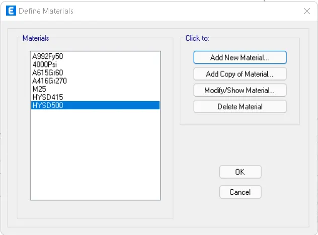
To define material properties
- go to define
- click on material propeties> add new materials
- add grade of concrete as M25
- grade of the steel Fe415 and Fe500
To define section properties
- go to define
- click on section properties> Frame section
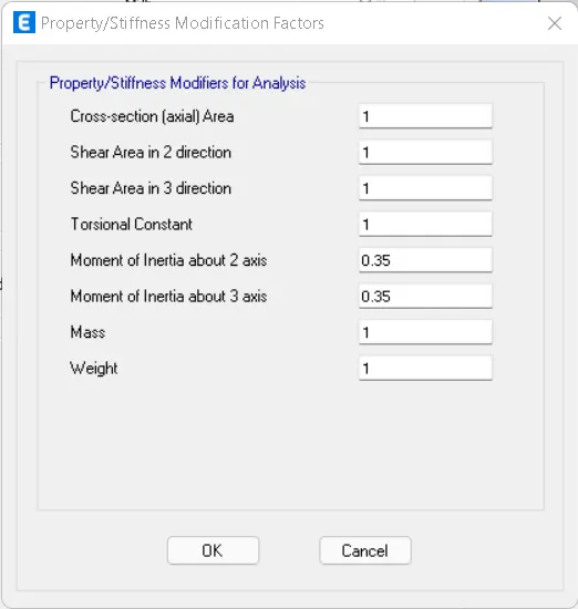
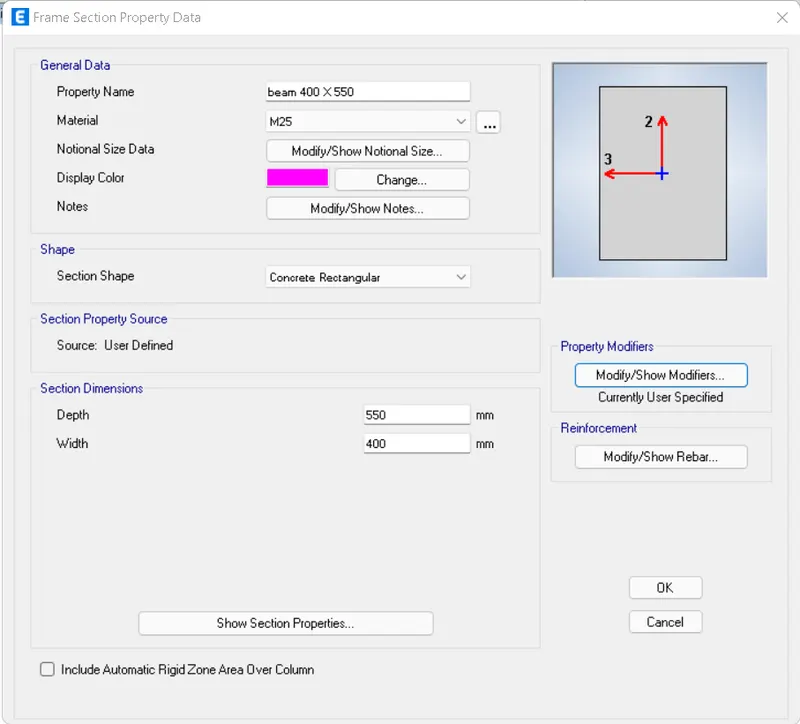
- define beam size as 400 x 550
- modify the properties and add rebar details
- go to define
- click on section properties> Frame section
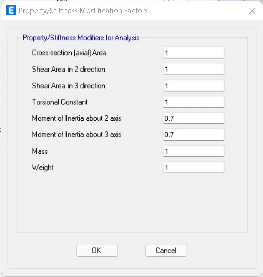
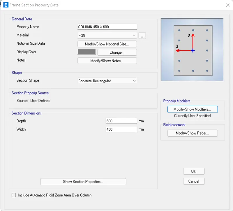
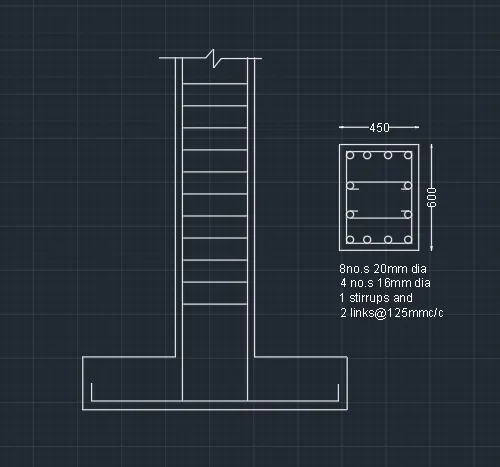
- define column size as 450 x 600
- modify the properties and add rebar details
To define slab properties
- go to define
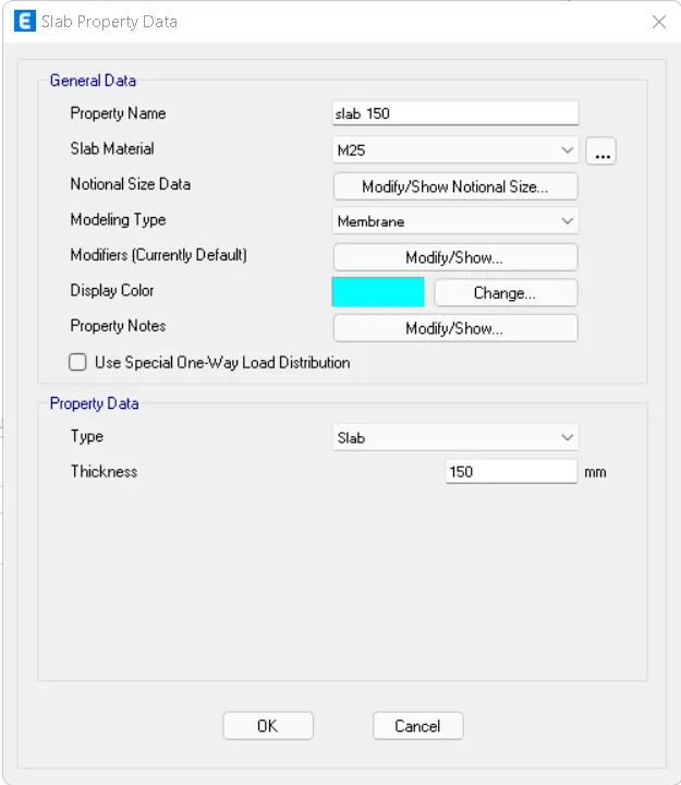
- click on section properties> slab sections> add new property
- specify the thickness of the slab as 150mm
- click on ok
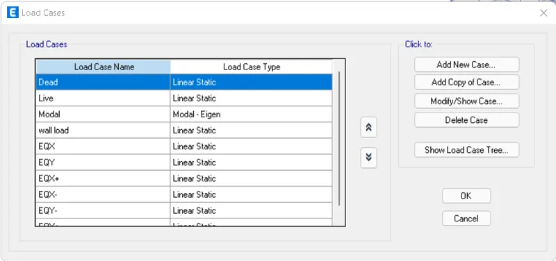
To define load patterns and load combinations
- go to define
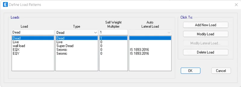
- select load patterns
- add wall load and earthquake loads
- modify the parameters of the earthquake load as per the zone of the location and type of the soil
- go to define
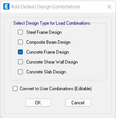
- click on load combination
- select add default design combination
- click on concrete frame design
- all the default load combinations will be added
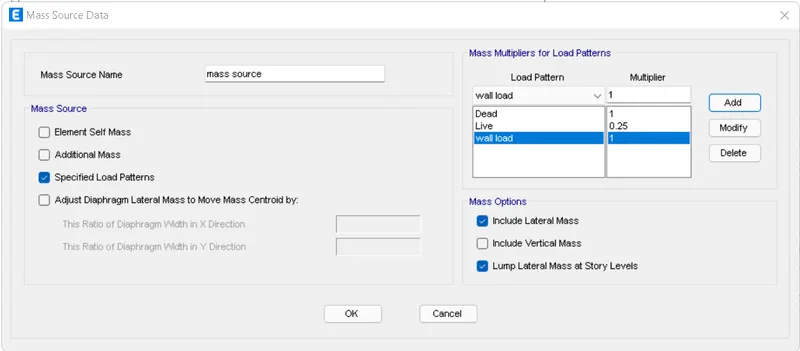
to define mass source
- go to define
- click on mass source
- add the load patterns and its multipliers
- click on ok
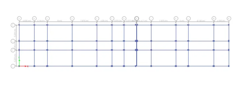
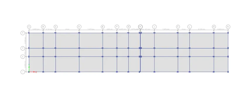
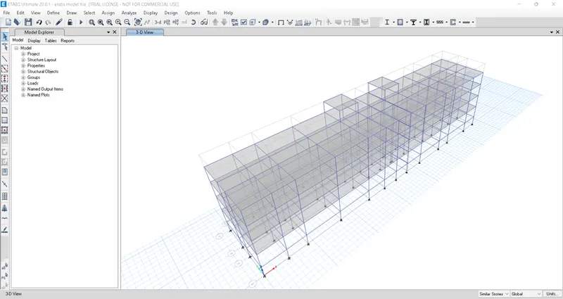
to add beams and colums and slab elements
- click on quick draw columns icon
- select the property of the column
- click on the grid intersections to draw the column
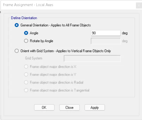
- to orient the column along y direction
- select the column
- go to assign>frame> local axes
- specify the angle as 90
- click on apply ok
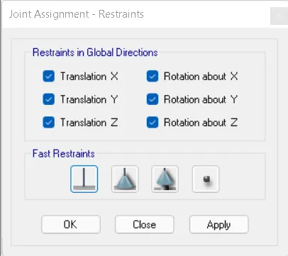
To assign base restraints
- open the base view of the structure
- select all the points
- go to assign
- select joints>restraints
- select the restraints as fixed restrains
- click on apply and ok
To assign wall loads and live loads to the structure
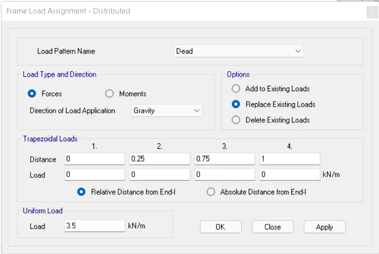
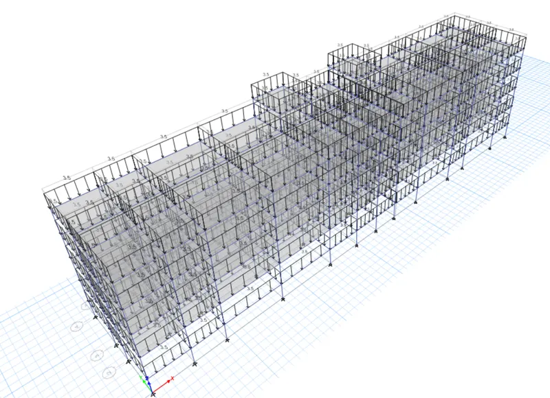
- to assign wall loads select the beam elements
- go to assign>frame loads
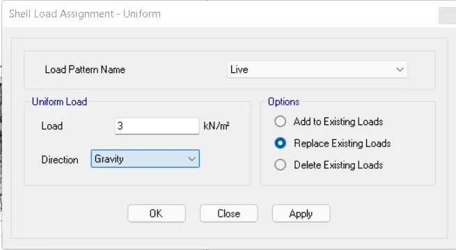
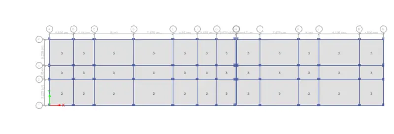
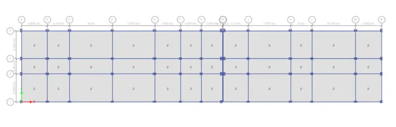
- select all the slab elements to assign live load
- to go assign
- click on shell loads> uniformly distributed
- live load for terrace is assumed as 2kn/m^2
- live load fo other storey is assumed as 3kn.m^2
- select all the slab elements
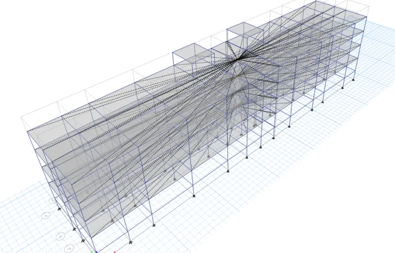
- go to assign
- select shells
- click on diaphragms
- now check the model for any warnings
- then run the analysis
- after the analysis has been completed we can view the deformations
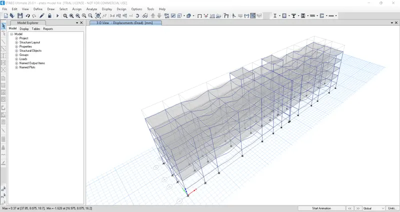
ANALYSIS RESULTS
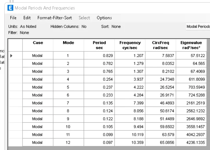
MODAL FREQUENCIES AND ANALYSIS
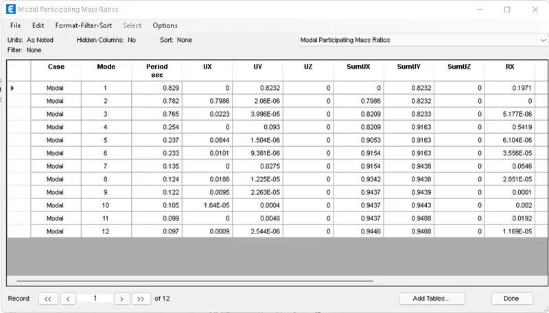
MODAL MASS PATICIPATING RATIOS
- after the analysis we need to design the structure
- go to design
- click on concrete frame design> start design check
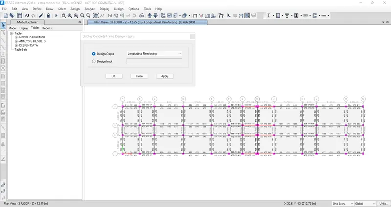
- after the design is complete we can view the reinfocement details of beams and columns
LONGITUDINAL REINFORCING DETAILS
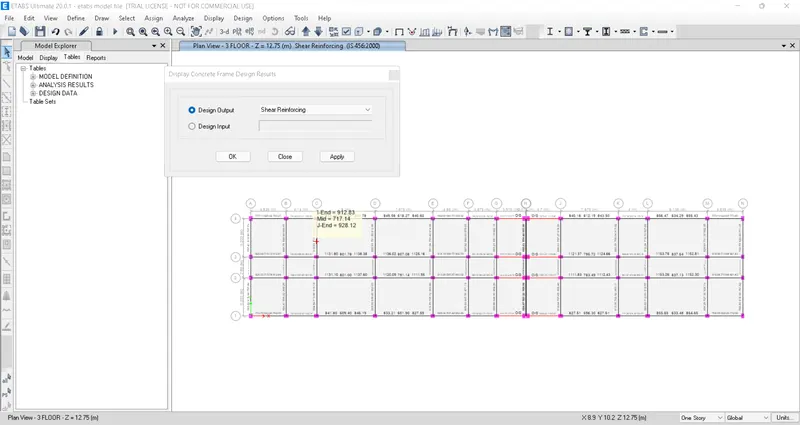
SHEAR REINFORCING DETAILS
REINFORCE DETAILS OF THE BEAM
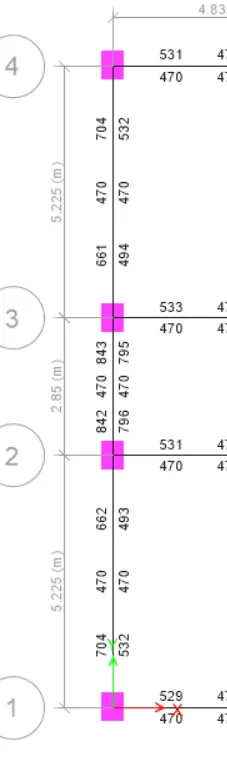
Considering the above beam as typical beam og fround floor reinforce detail drawing is provided
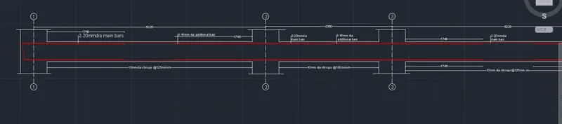
2-20mm dia bars are provided as main reinforcement along the length of the beam
3-16mm dia bars are provided as additional reinforcement
shear reinforcement of 10mmdia stirrups@125mm c/c in the end spans and 10mmdia@100mmc/c in the mid span
REINFORCING DETAILS OF THE COLUMN
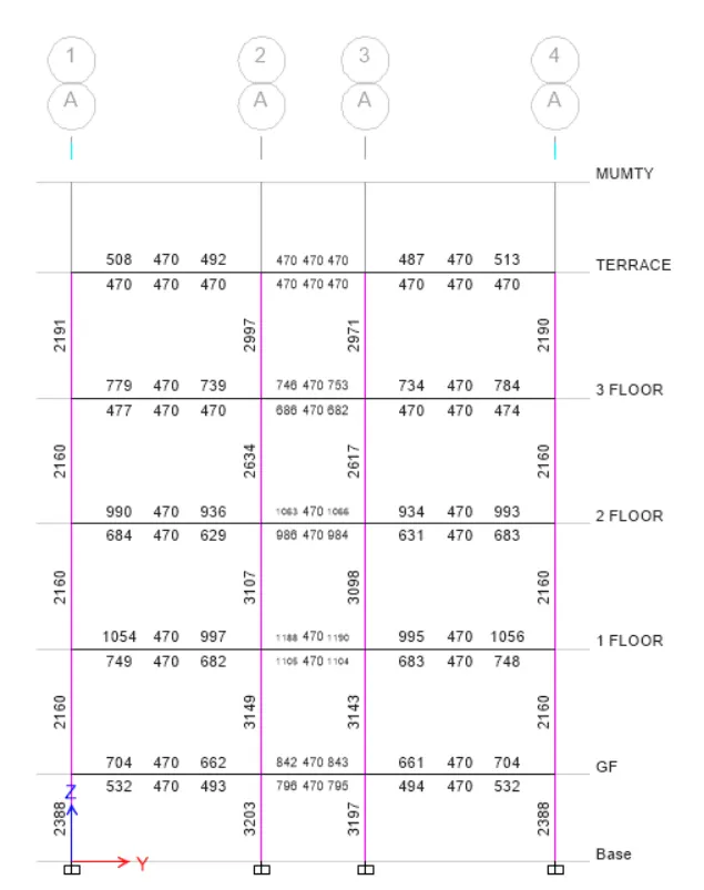
column along the grid A2 is considered as typical column and reinforcing details are provided for the same with a max Ast of 3203mm^2
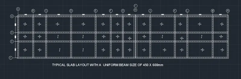
FRAMING PLAN OF TYPICAL FLOOR
TO DESIGN FOUNDATION FOR THE ABOVE STRUCTURE
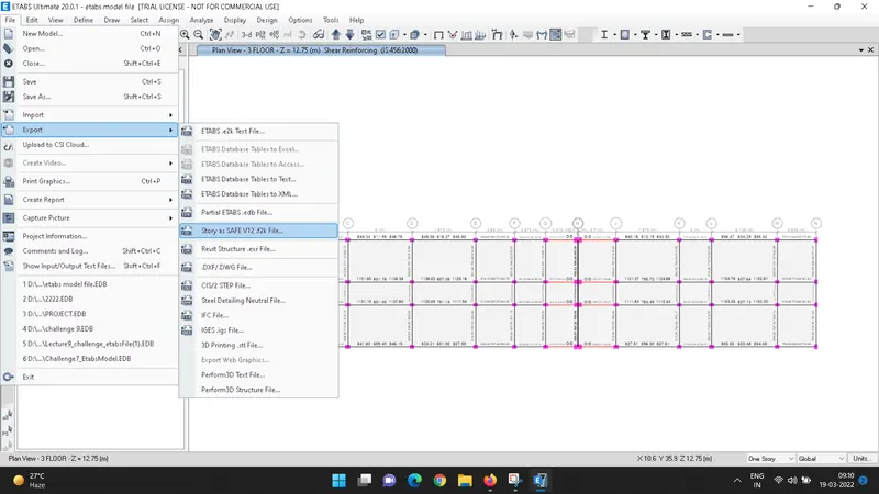
- firstly export the details of the base restraints and its reactions to safe
- go to file>export
- select the format as story as safe f2k file
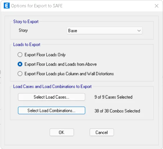
- click on ok
- now open the safe software
- click on import
- select the file and open
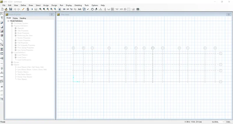
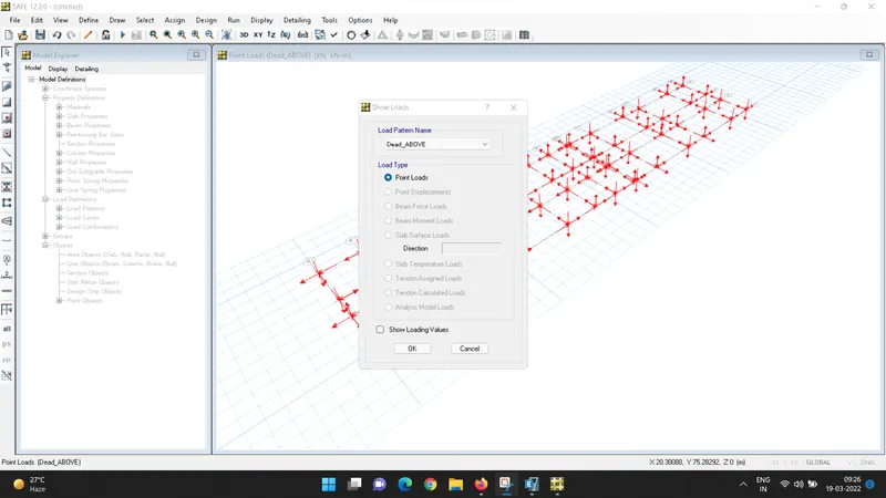
- all the loads and load combinations are also imported
SAFE MODELING
given data:-
- building rest on type 3 soil
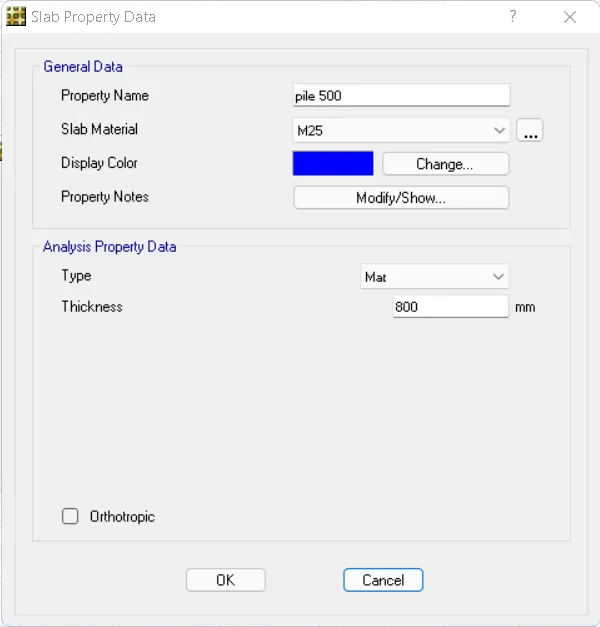
- dia of the pile is 500mm
- length of the pile is given as 10m
- capacity of individual pile is 280kn
- point spring is calculated as AE/L
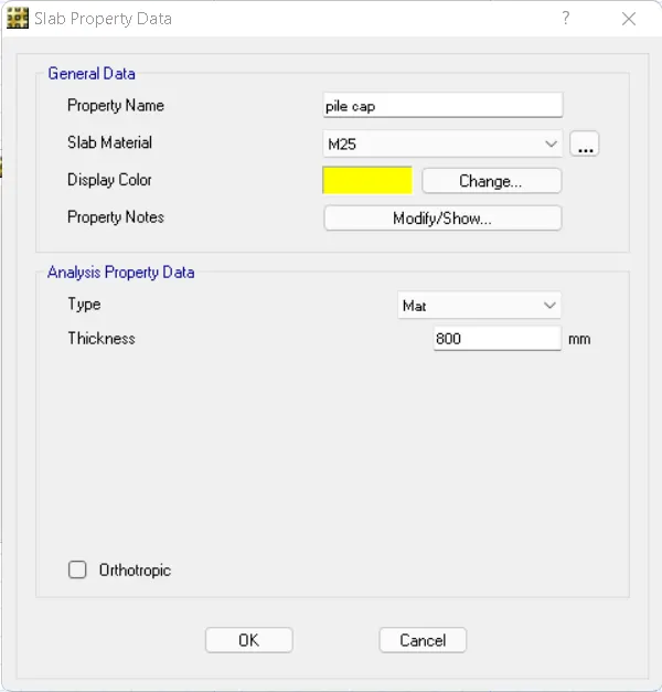
- assume the thickness of the pile cap as 800mm
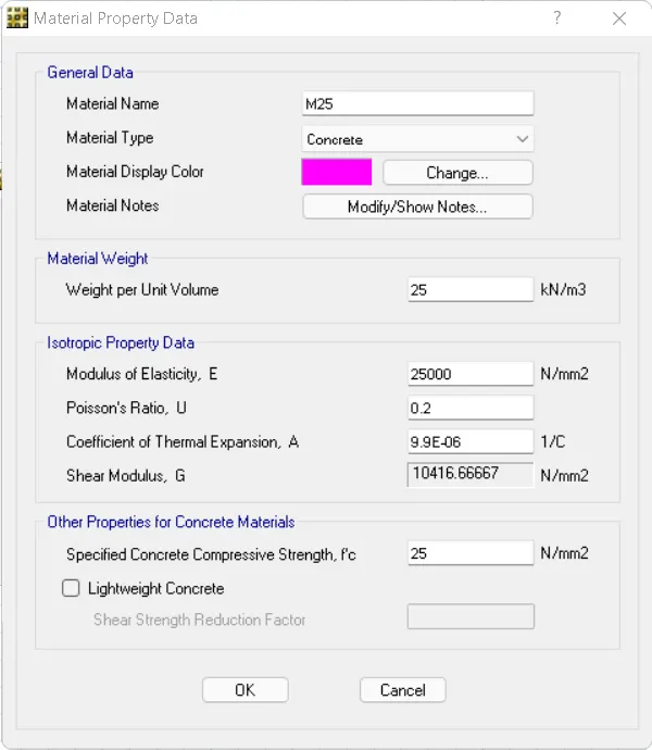
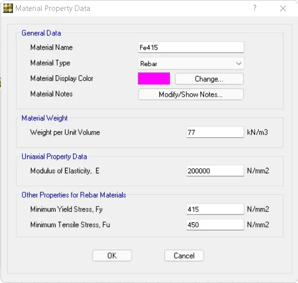
DEFINE MATERIAL PROPERTIES
- go to define
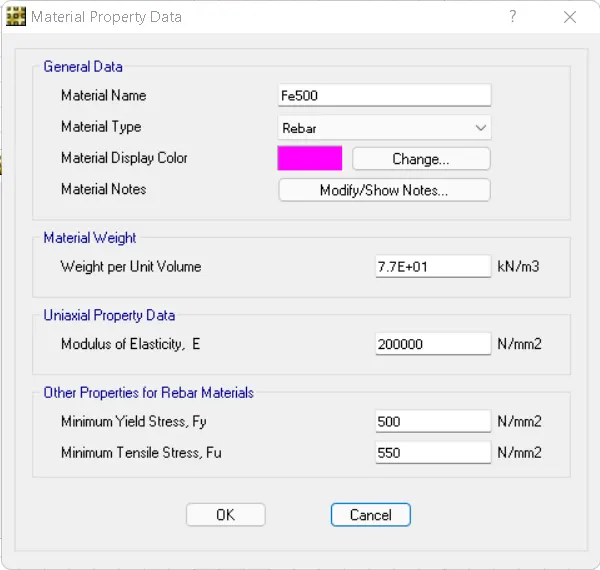
- Click on materials> add new property
- add grade of concrete and rebar material
to define slab propeties
- go to define
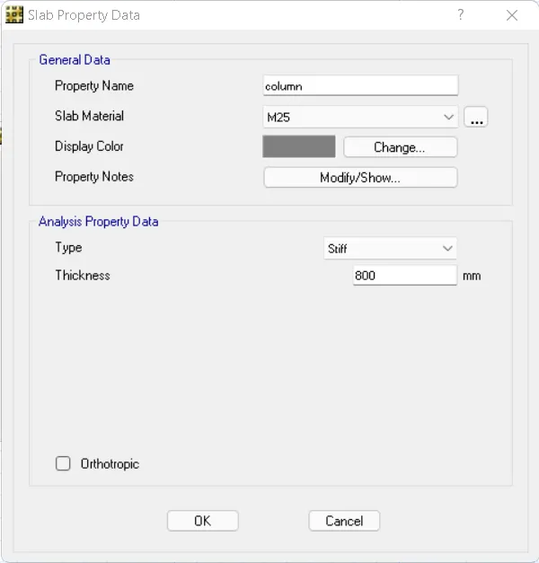
- click on slab properties
- select add new property
- add propoerties of pile cap, piles and column and modify its parameters
Add pilecap, piles and columns to the model
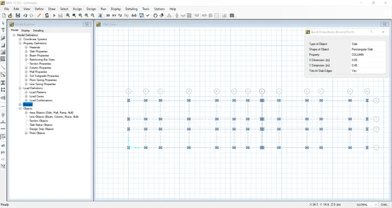
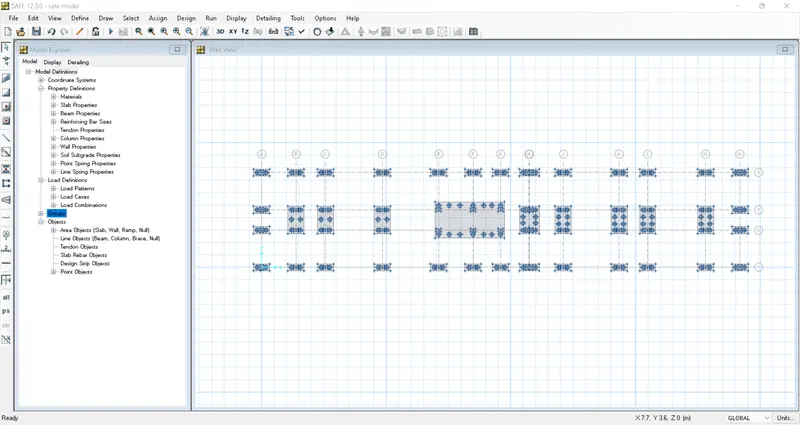
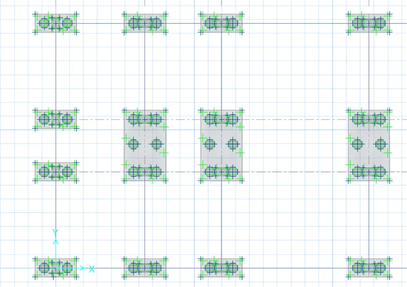
- then add piles with a distance of 3d between the adjacent piles and at a distance of d from the edge of the column
- draw the pile caps
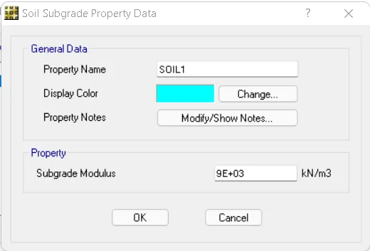
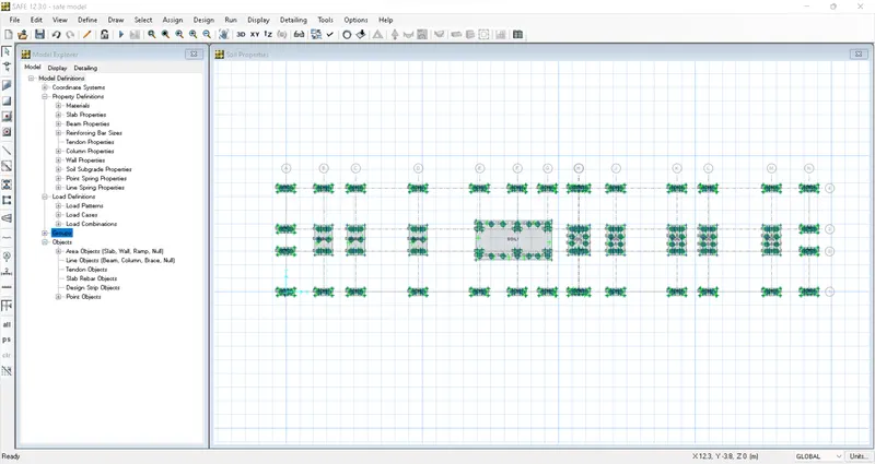
to define the subgrade properties
- select all the elements
- go to assign
- click on support data> soil properties
- specify the elastic subgrade modulus and click on ok
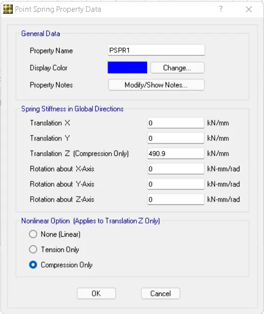
to assign pile springs
- AE/L=196349.5 x 25000/10000=490873.85n/mm^2
- 490.9kn/m^2

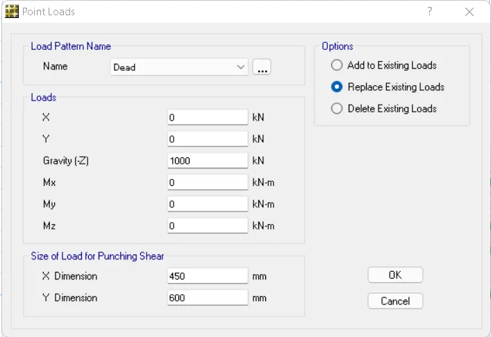
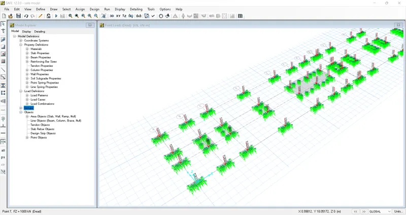
to assign loads
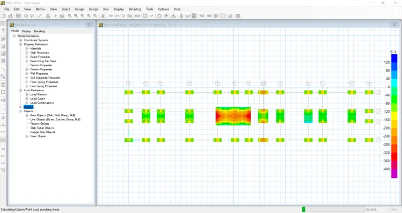
run analysis
To add tie beams between the pile caps to transfer the loads effectively
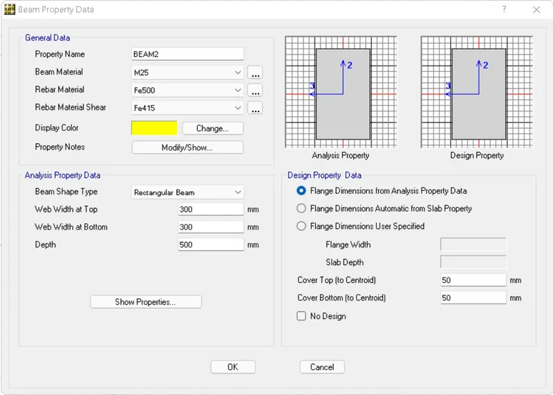
define the beam property with a uniformsize of 300 x 500
add the beam to the model
Add the design strips to view the moments
go to show slab design
to view the moments and also to view the reinforcement details
RESULTS:-
- punching shear is above 1 so redesign the foundation by increasing the thickness
- reactions are within the capacity of the piles