Project 2_Design & Analysis of a Hostel building at Guwahati, Assam
Aim: Design & Analysis of a Hostel building at Guwahati, Assam
Introduction:
In this project, participants will get to experience the entire design process from modelling, analysis, design, and preparation of construction drawings. The architectural drawings of a G+3 RCC building is provided. The following information on the building is to be used:
- Location – Guwahati, Assam
- Function – Hostel block in an academic institute
Procedure:
The Above mentioned Project is done as per Is 1893 Part-1 2016 the following procedure is as follows,
Step-1
- Open E-tab Software and Select a new file and save the project as Final Project.
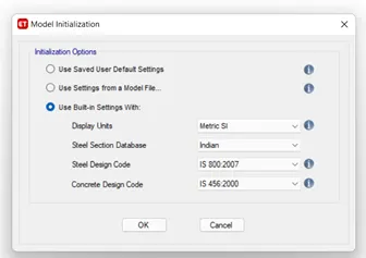
- Now the is step is to set the Model initialization.
- Select the built in option.
- In which select unit as metric SI.
- Steel section database as Indian.
- Steel Design code as IS 800 2007.
- Concrete Design code as Is 456 2000 and press ok as shown below.
Step-2
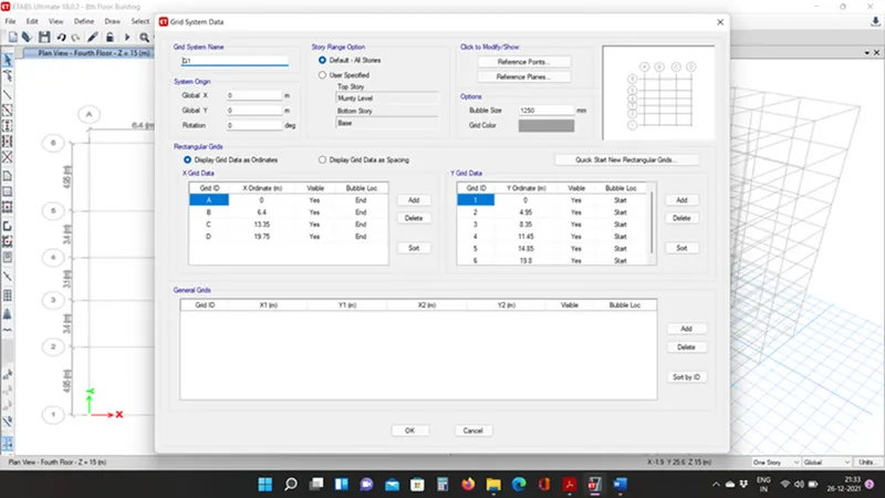
- Now Giving the Spacings of Grids.
- Select grid only option and press ok.
- Now select display grid data as spacing.
- and provide spacing as Shown in Architectural Plan Given by architect
- 14 grids along x and 4 grids along y as mensioned in question.
- As shown below.
Step-3
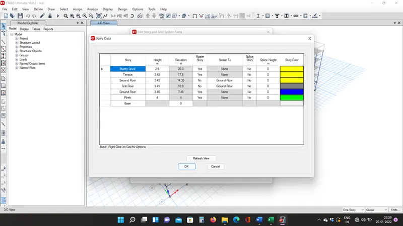
- Select the Storey Data and input the data as mensioned.
- That is select 5 story that is Plinth level and 3 Floors and Roof.
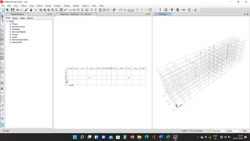
- With 1st floor as master storey and remaining 3 floors as its copy as shown below.
- After completely renaming the Storey press ok.
Step-4
- Now its time to define the materials Properties
- Select concrete as Indian and M30 grade.
- For steel select Rebars Indian ie HYSD 415 grade.
- After completing Selct ok as shown Below.
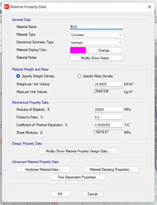
Step-5
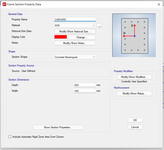
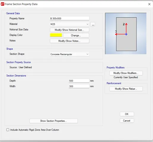
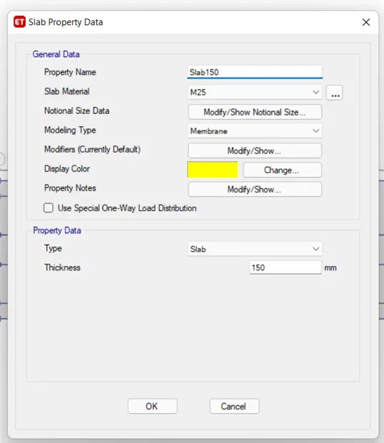
- Now give Section Properties for Column, Beam and Slab ie.,
- For Column select size as 450x600mm
- For Beam 300x500mm
- And For Slab 125mm thk.
Step-6
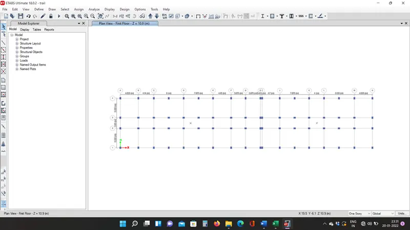
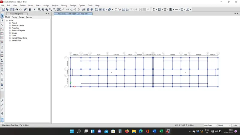
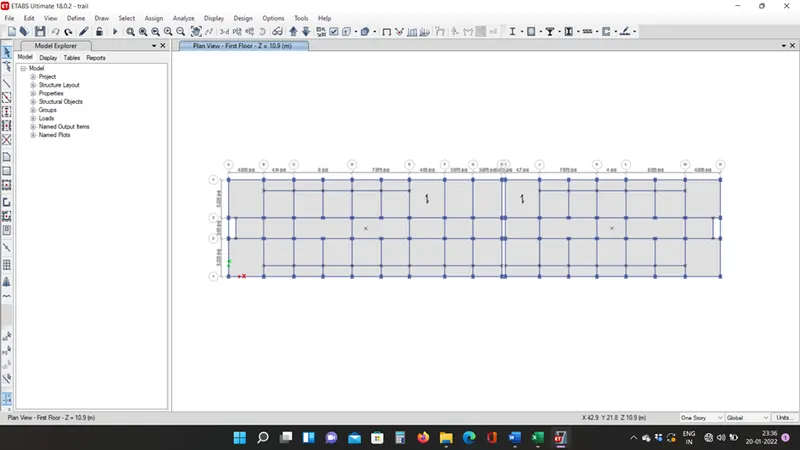
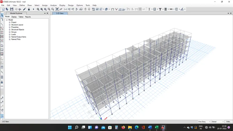
- Now placing of Columns and Beams is done.
- select the quick column option and select Column C1 i.e., 450x600 and place it where required.
- Simillarly select quick beam and select the grids where beams are required.
- and also select quick slab selection and place the slab of given size i.e., 125mm thk.
- And Must be noted that the all storeys option should be selected.
Step-7
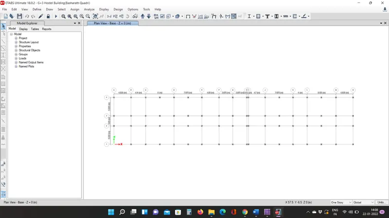
- Now its time to assign the Supports whether fixed or hinge or pined
- In this case hinge support is given that is restricted along x and y only.
- it is done by selecting the points from base plan and assigning the hinge support as shown below.
Step-8
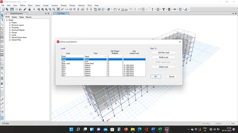
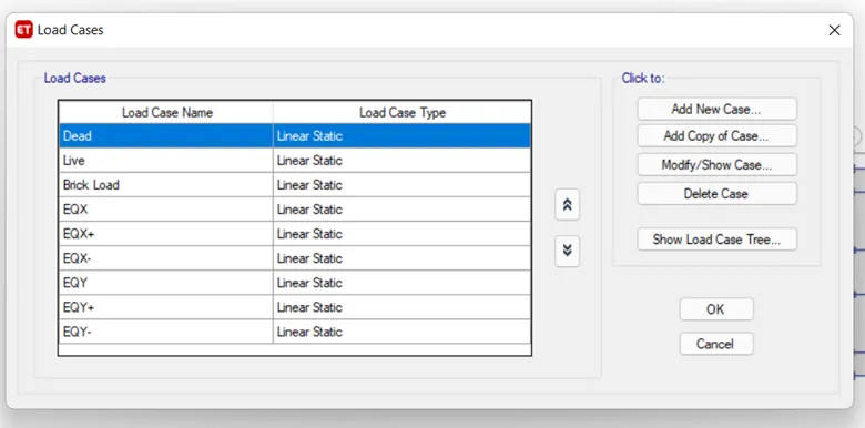
- Defining of loads acting on the building that is
- Dead load, live Load, Wall Load, and Earthquake load.
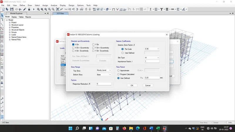
- For Earthquake load There loads are given those are EQ in X, EQ in X+, EQ in X- and EQ in Y, EQ in Y+ and EQ in Y- As shown below.
Step-9
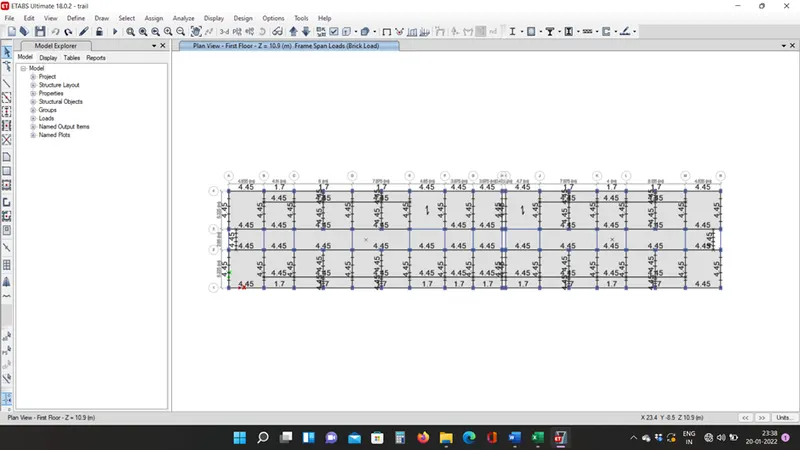
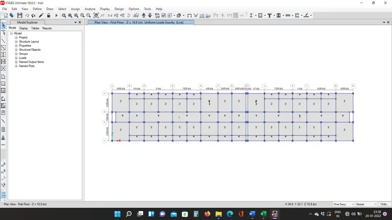
- Assigning the Live Load, Dead Load to the Structure
- Brick load =4.45N/m
- And Live Load as 4 for Corridor, 2 for Room.
- and Assign the loads as shown in Is 456 2000
Step-10
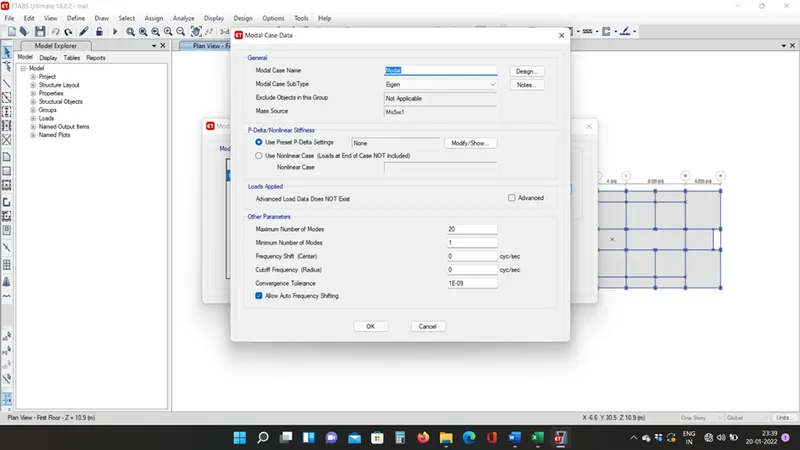
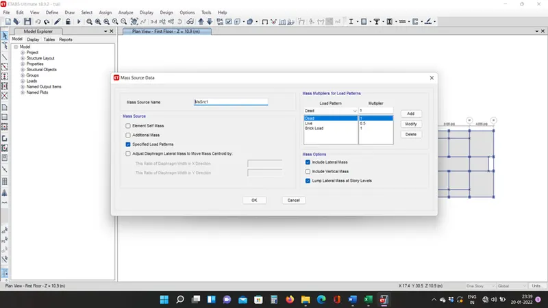
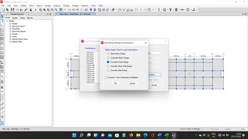
- Now Apply the Modal Case and Modal Mass.
- And Select the Load Combination and also Select the Load Cases as shown Below.
Step-11
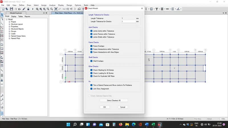
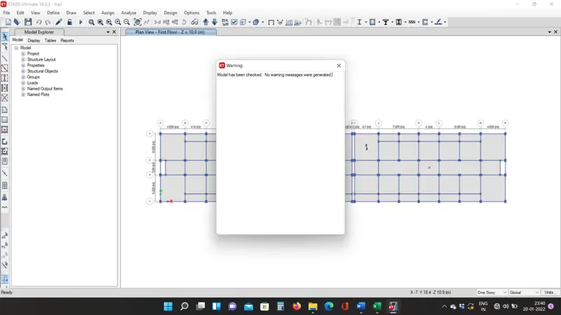
- Now Apply Run the Analysis and Check Whether th Modal is Good.
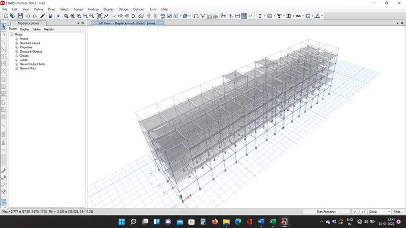
- Next Analyse the Model.
- And Hence the modal is Analaysed as Shown Below.
Step-12
- Now the Neccesary check has been checked as per Is 456 2000 and IS 1893 2016
- Hence the Model is Checked and Redy for the Designed
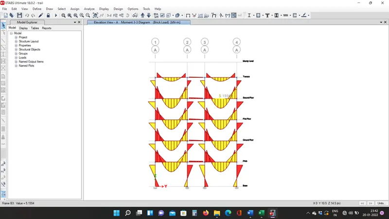
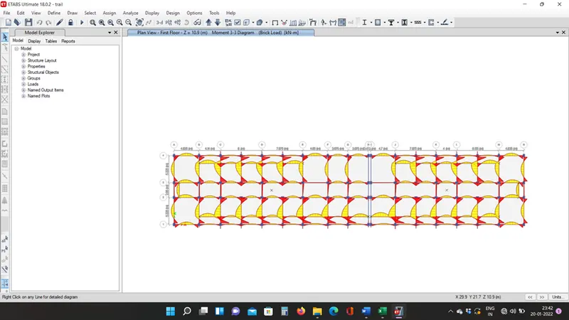
Step-13
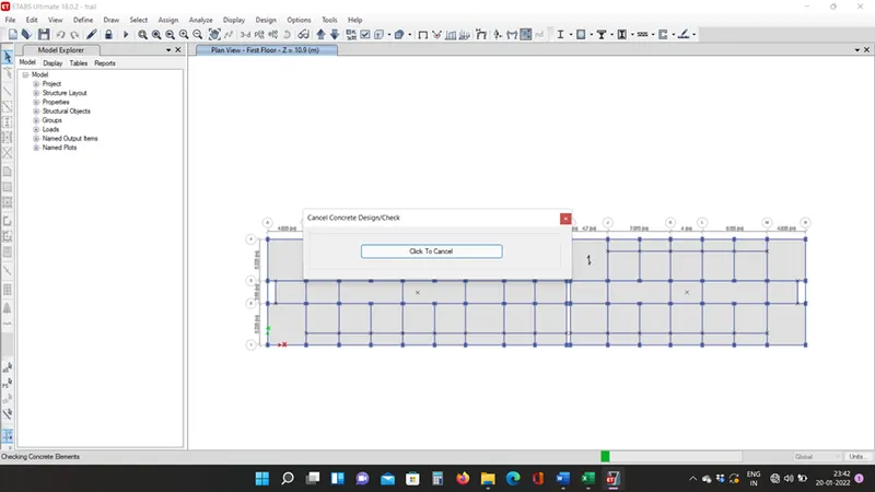
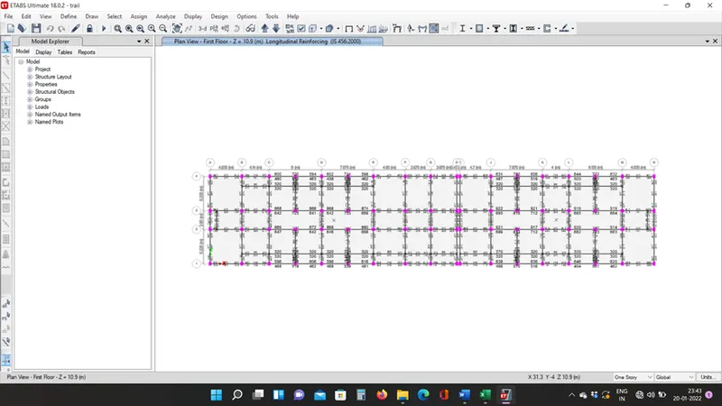
- Now after Completing the Modeling now select the Design the beam by selecting concrete design logo
- Now Select the Beams and Selct the lonitudinal reinforcement and Shear Reinforcement
- And Also do the same For Column as shown Below
Step-14
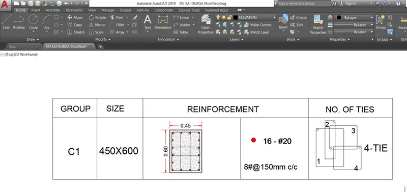
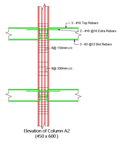
- Now Select the Column of A2 column
- And Selcect the Longitudinal Reinforcement
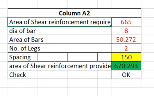
- And Select Shear Reinforcement and Also Check for Rebar Percentage that is it should not be more than 4
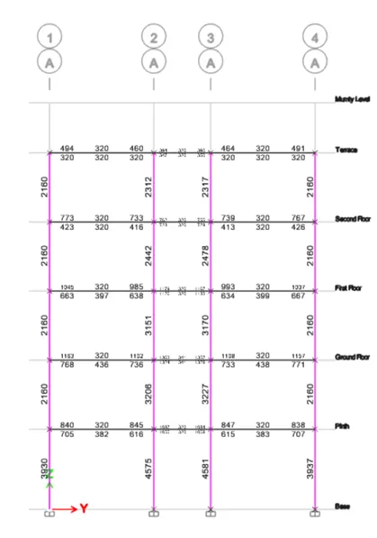
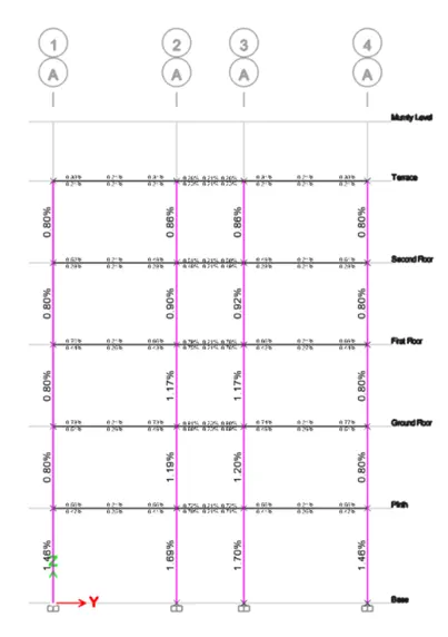
- Hence the Longitudinal Reinforcement of Column A2 Is 4575 N/mm
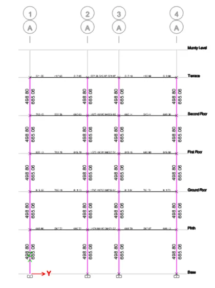
- And Shear Reinforcement 498.80and 665.06 at top and Bottom
For Shear Reinforcement
And Shear Reinforcement 498.80and 665.06 at top and Bottom
Step-15
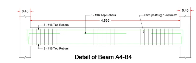
- Now Select the Beam of A4-B4 Beam
- And Selcect the Longitudinal Reinforcement
- And Select Shear Reinforcement and Also Check for Rebar Percentage that is it should not be more than 2.5
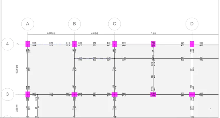
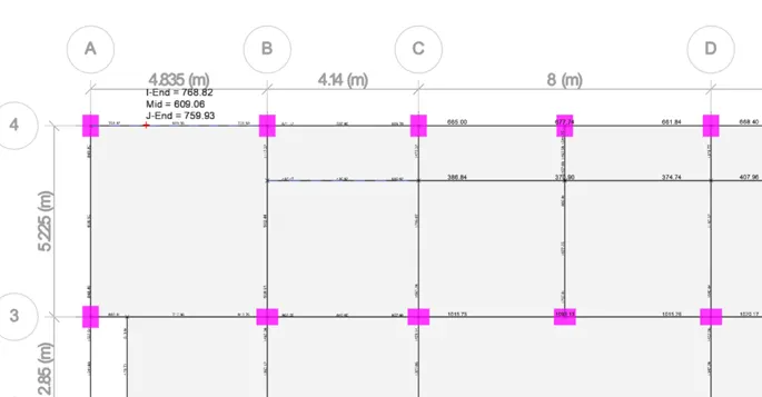
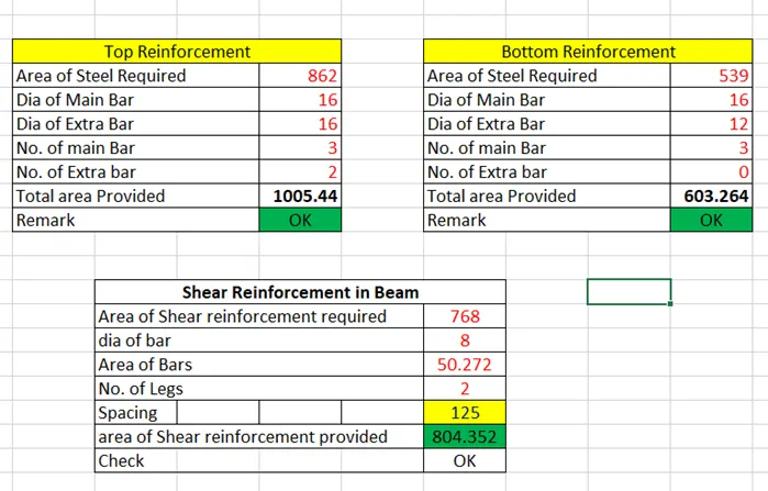
- Hence the Beam Shows Required Rebars is that is 862
- And Shear as 768
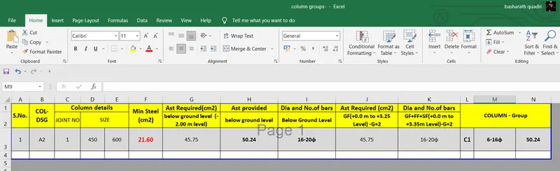
- Hence the Sheet is already prepared we just need to provide the value as shown Below
Step-16
- Now the time for Foundation in order to design for Pile Foundation Necesaary details has to be Calculated.
- So check the Load acting on the Column A2
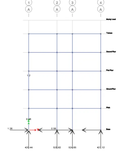
- So now Go to Safe 2016 Software and Design Manually
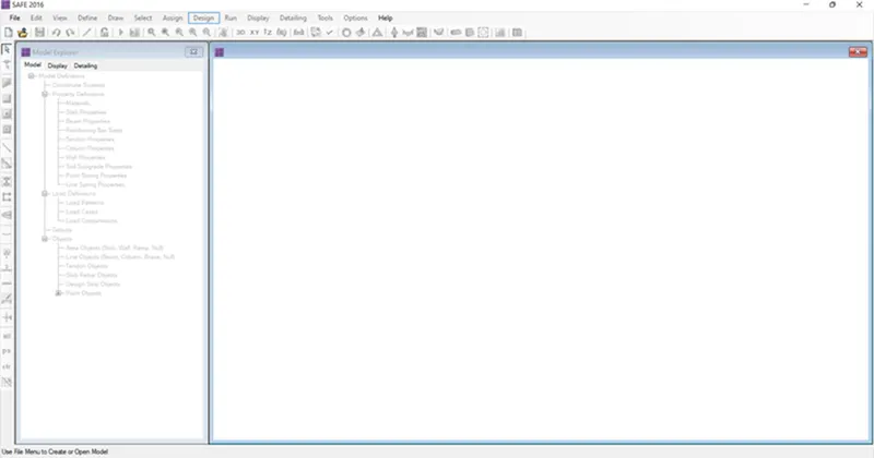
- Open New File And Save as Footing
- Open the Safe 2016
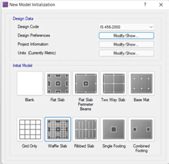
- Select the file option and Select new model
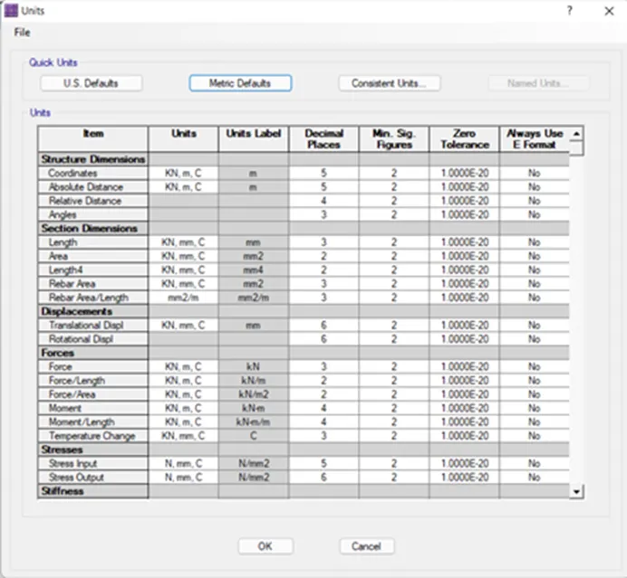
- Select the IS code and all necessary modifications as shown below.
Step-17
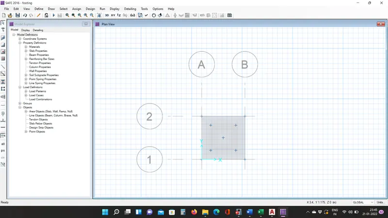
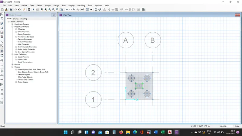
- Select Grid only option and give proper details.
- Add the dimension of Pile cap and column.
- As per IS 2911 part-2 and SP 34 the edge of pile to cover should be 100mm to 150mm so we assume 200mm
- And the distance between two pile should be 2.5D hence for 500mm dia pile 1250mm is required.
- The Load given is 780 KN and pile capacity is 200KN hence no of pile =4no.s as shown below
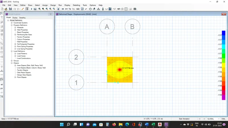
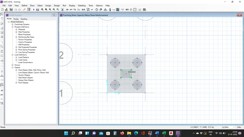
- Hence the Pile Foundation is Designed As per Is 456 2000
- This Completes the Project 2 Of Designing G+3 Hodtel in Guwait, India
----------------------------------------------------------------------------------------------------END-------------------------------------------------------------------------------------------------------------