Project 2_Design & Analysis of a Hostel building at Guwahati, Assam
AIM: To experience the entire design process from modelling, analysis, design, and preparation of construction drawings using ETABS and SAFE software of a G+3 RCC building which is loacted in Assam.
INTRODUCTION:
Given bulding is a G+3 to be constructed to serve as hostel block for a academic institue,loacted at Guwahati, Assam.
-
The walls will be made of AAC blocks. Other loadings are to be calculated as per the architectural drawings.
-
The buildings rests on type 3 soil. Piles of length 10 meters and 500 mm diameter with a load-carrying capacity of 280 KN is to be used.
-
The ground floor level will be at a height of 2 meters above the existing site level to avoid floodwater enter the building.
-
M25 grade of concrete with Fe500 for longitudinal reinforcement and Fe 415 for shear reinforcement is to be used.
The following design IS codes will be required for reference:
- IS 875 part 1
- IS 875 part 2
- IS 13920
- IS 1893
- IS 2911 part 2
- IS 456
- SP 34
PROCEDURE:
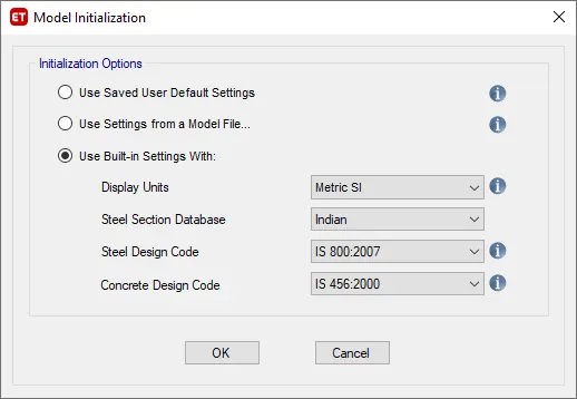
- open etabs software>new model>set the units and standards.
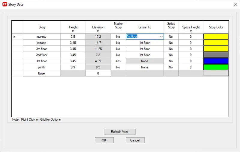
- set the grids and storey as custom and edit.
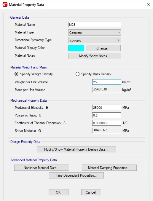
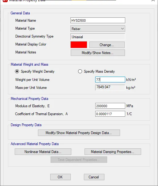
- define the properties for concrete as M25 and rebar as HYSD500 and HYSD415.
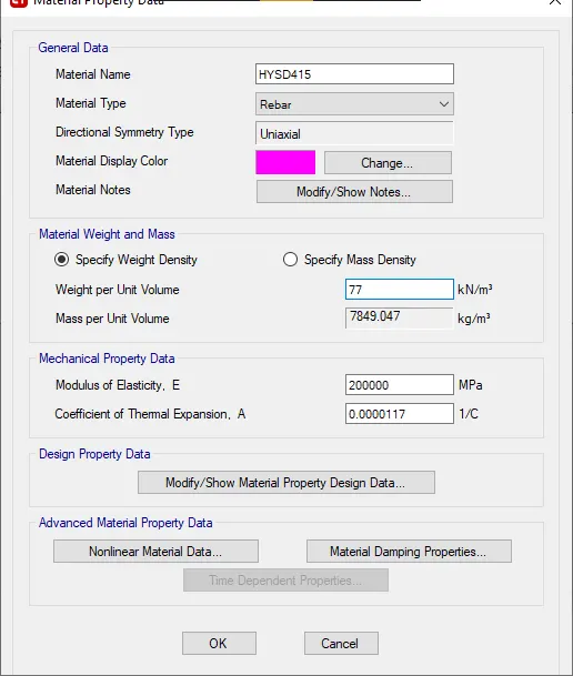
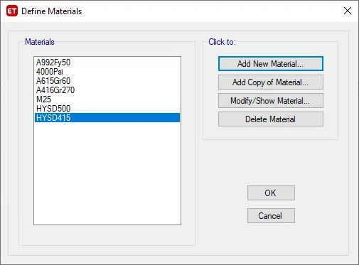
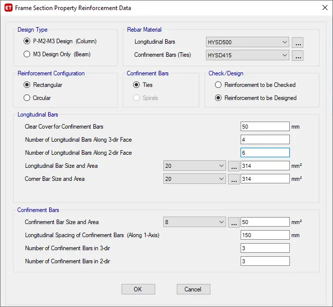
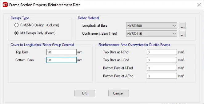
- define the materials for column(400x600mm and 600mmx400mm) and beam(300x500mm).
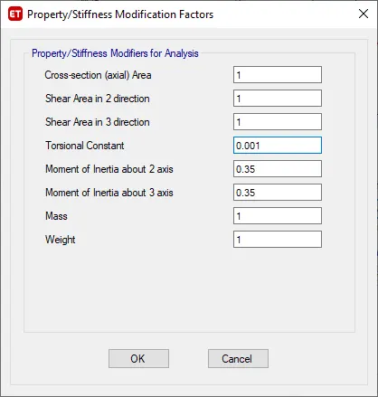
- define the slabs for floors and staircase.
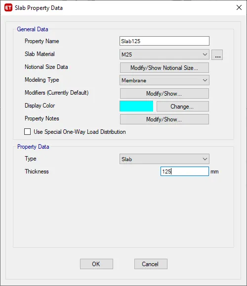
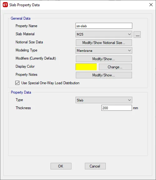
- select quick draw column annd place the column.
- similarly quick draw beams and slabs.
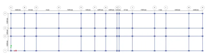
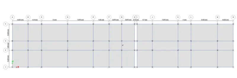
- select joints in base and assign restraints as fixed.
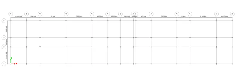
- once geomteric model,define loads and assign them.
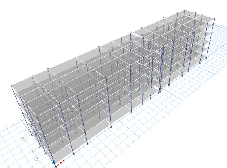
now for load,as per IS 875 part 1-
dead load is self weight of the members-
brickwall load(AAC blocks,6kN/m^3),height of the brick wall is =height of floor -depth of beam=3.45-0.45=3m
given thickness of brickwall as 0.2m
brickwall load=6*3*0.2=3.6 kN/m
assume plaster thicknness as 0.024 m and density of plaster as 20kN/m
plaster load=0.024*3*20=1.44kN/m
total brickwall load,3.6+1.44=5.04 kN/m,approx 5kN/m for each story.
for paraphet wall total brickwall load=(0.9*2.6*6)+(0.024*20*0.9)=1.5kN/m
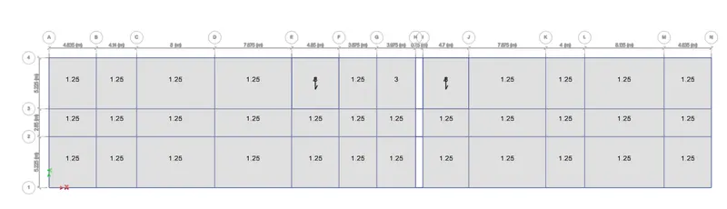
for floor finish given vitrifies tiles,1.25kN/m^2
and for staircase floor load as 3kN/m^2.
live load as per IS 875 part2,
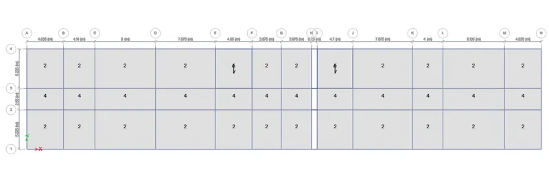
- rooms,toilet and wardeners room=2kN/m2
- recreational and kitchen room=3kN/m2
- dinnig room=4kN/m2
- cooridors and passage=3kN/m2
- store room=5kN/m2
- balconies as 4kN/m2
earthquake load as per IS 1893:2016,
- Gwahati,Assam comes under seismic zone V,Z=0.36(table 9)
- given soil type as 2
- importance factor of the building is 1
- moement resisting frame with mansory infills clause 7.6.2
- time period ,T in x-direction as Ex=0.09*17.2/sqrt67.8m=0.19sec
- T in y-direction=0.09*17.3/sqrt13.3=0.424 sec
load assigning-
- assign brickwall load for all beam by setting simialr floors.
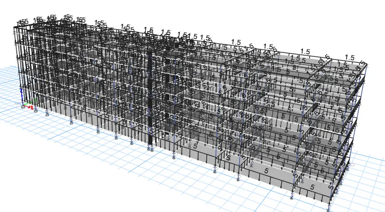
- assign live load for slabs 2kN/m2 for all rooms,3 for kichten and 4kN/m2 for dinning in GL.
- assign floor finish for slabs.
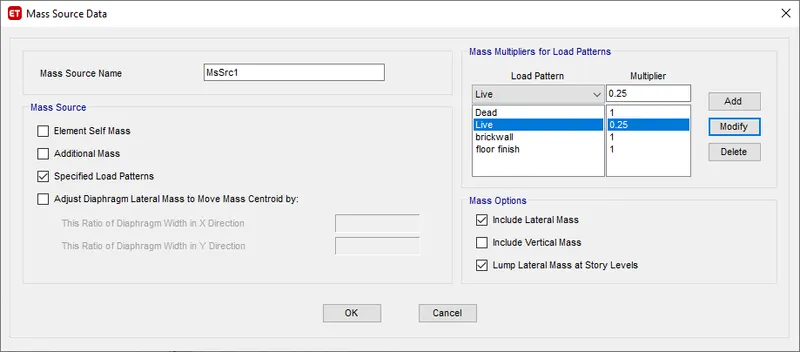
- assign earthquake load,mass source>combination of specified.
- define modal properties.
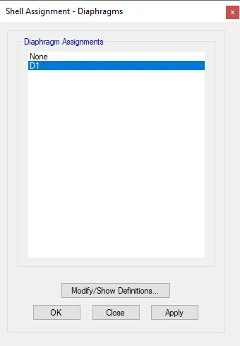
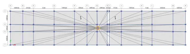
- assign diaphragm load for all slabs.
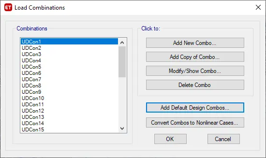
- define load combination>default.
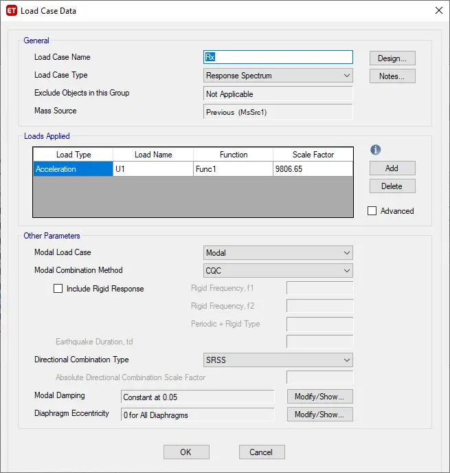
- for response spectrum,define load case for Rx and Ry.
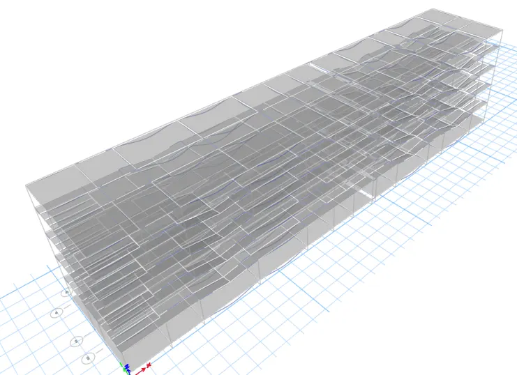
- check for model overlapping,analyze>check model.

- run analyses.
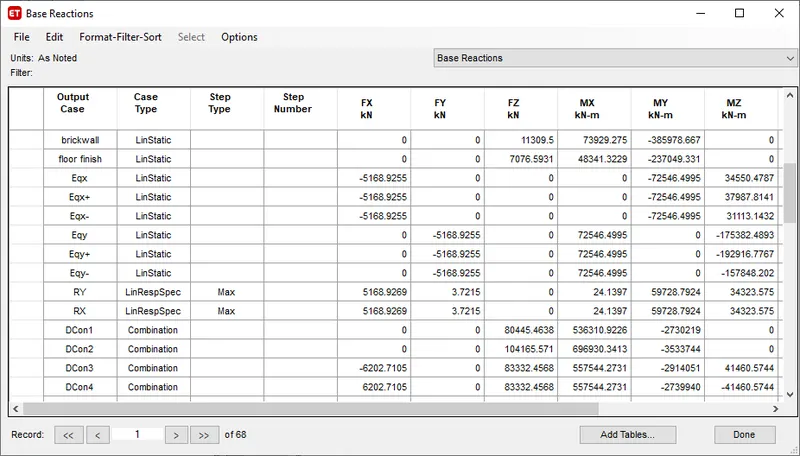
check for response spectrum ratio-
display>show table>strcuture>base reaction.
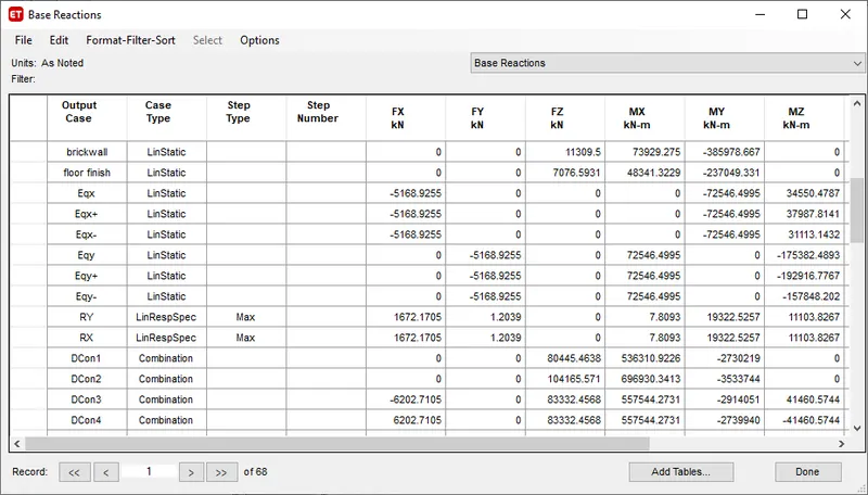
scale factor need to be increased by ration 3.
check for modal number-
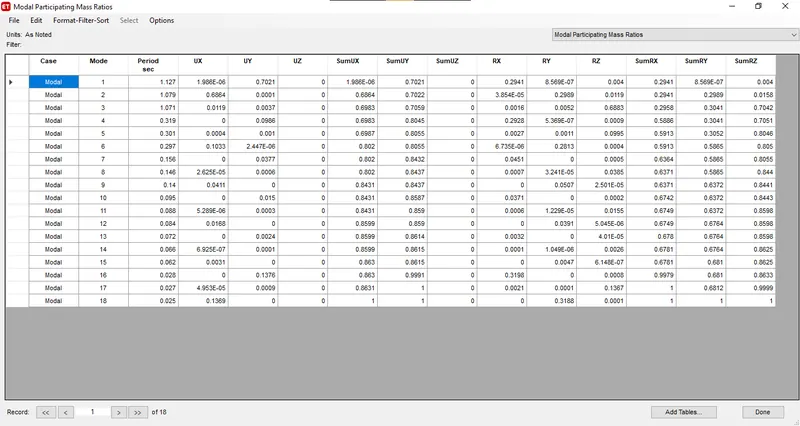
the sum of first two fundametal natural period in translational is greater than fundmental natural period in torsional direction,1.127+1.079>1.071.
Ux=69%
Uy=70%
Rz=69%,Ux and Rz need to be made bit stiffer
18 number of mode will capture more than 90% in all 6 degree of freedom.
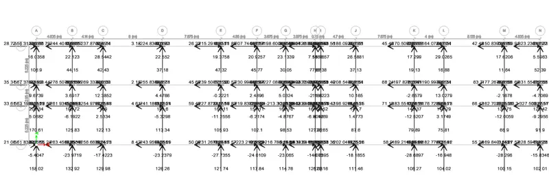
show base reaction-
run frame design analyses-
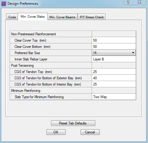
check for deisgn perference
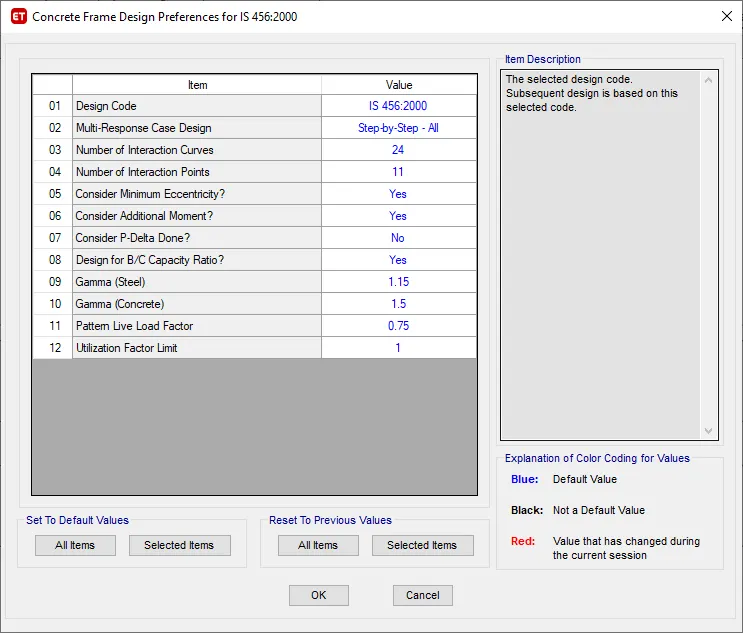
start design/check-
by default longitudinal reinforcement details will be showed after frame design
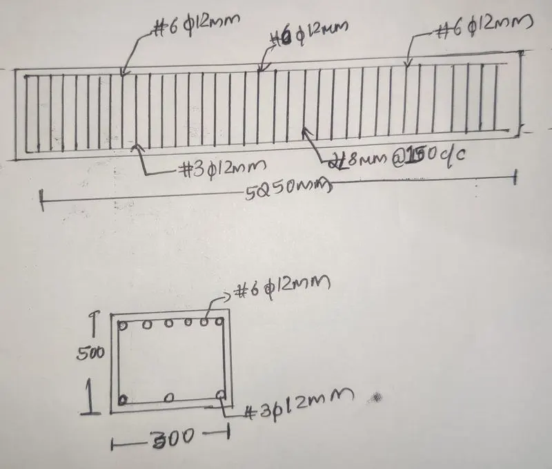
beam reinforcement detail at groundlevel is
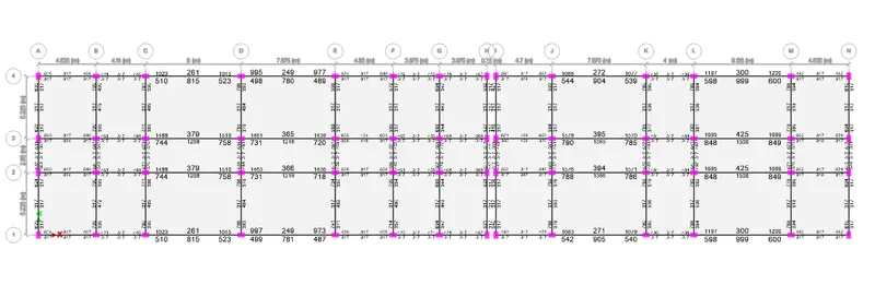
lets consider beam reinforcement of B@4-A grid,
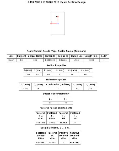
logituidinal reinforcement required is 630mm^2.
miimum reinforcement required to be provided as per IS 456:2000 is Ast/bd=0.85/fy
Ast=(0.85*300*500)/500=255mm2
630mm2>225mm2,hence ok.
maximum longituidinal reinforcement required=0.04bd
0.04*300*500=6000mm2
630mm2<6000mm2,hence ok.
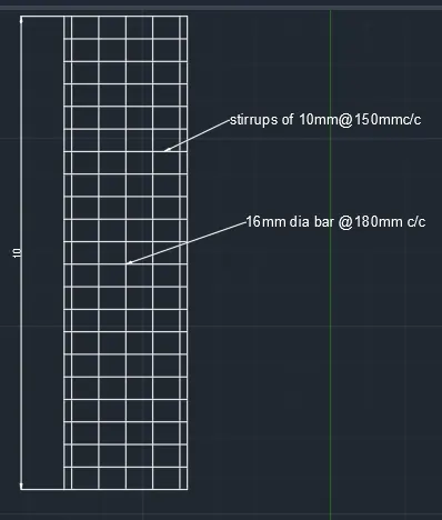
for shear reinforcement,provide 2L 8mm diameter stirrups @150mm c/c throughtout.
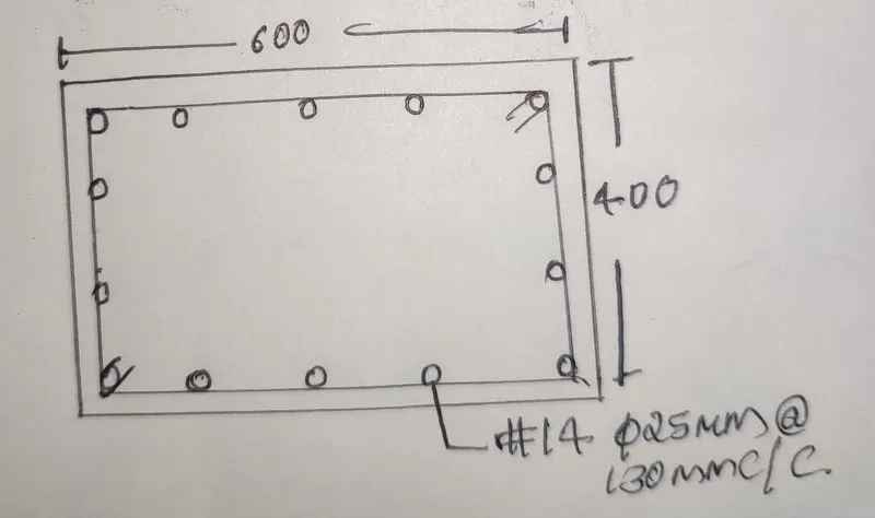
lets consider column 1-A,
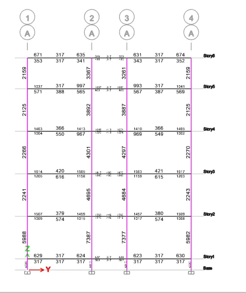
the maximum reinforcement area in 1-A colum is 5988mm2
total number of longitudinal bars=5988/3.14*25*25/4=13
[provide 13 number of 25mm dia bar,Asc provided=6378>5988,hence ok.
provide 2L 8mm dia stirrup at 150mm c/c spacing.
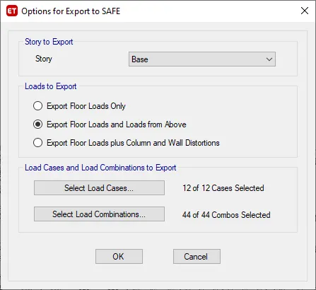
now export the file to safev12 file-select base and all load combination and cases.
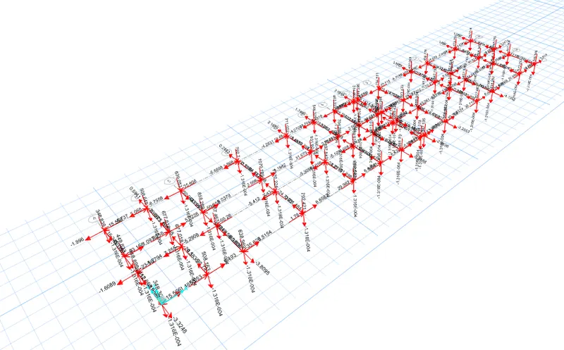
- define the properties,M25 and fe500.
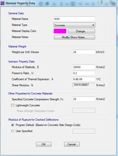
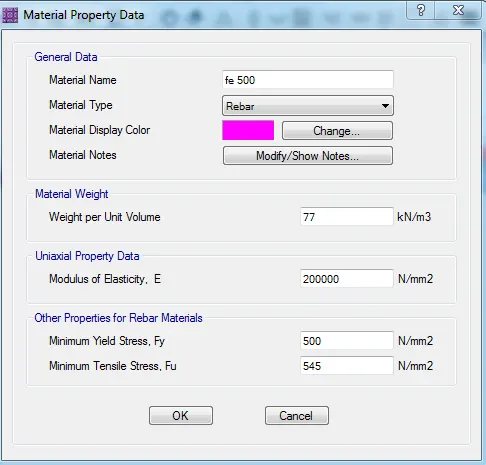
- define slab properties for pile mat,cap and column.
- define soil property.
- now use quick draw by area commands for deining size of footing along with pile cap.
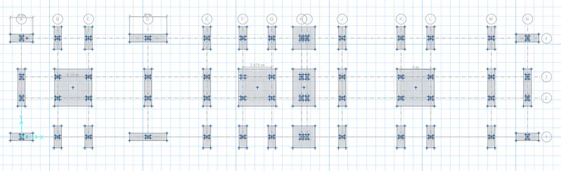
- assign spring constant for pile cap.
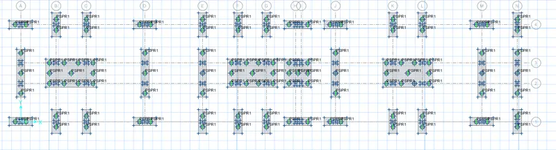
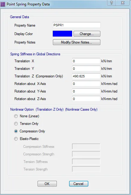
- assign the soil property.
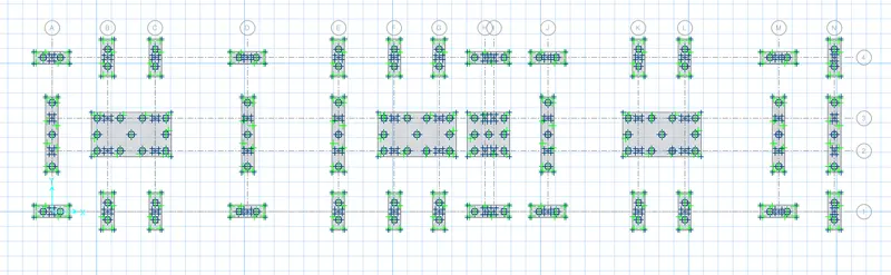
- recheck for design references and run the analysis and design.
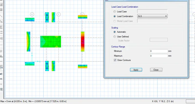
- check for deflection.
deflection under all service load and ultimate load combination is within 25mm,hence ok.
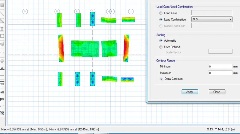
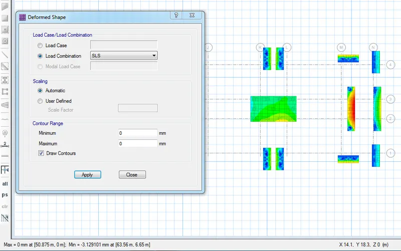
- check for punching shear.
punching shear was found to be within 1,hence ok.
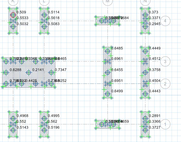
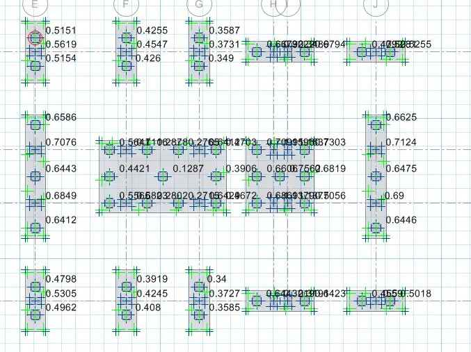
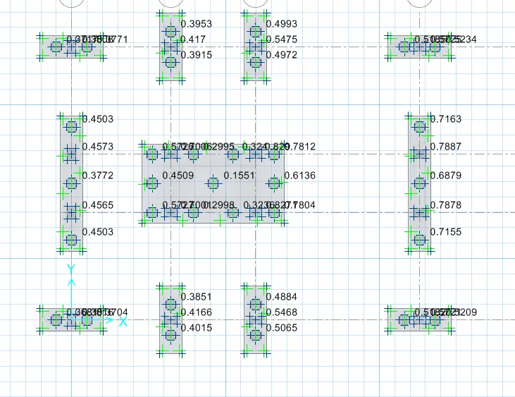
- check for reaction force.
the soil bearing soil exceeded 150kN/m^2,hence need to increase pile numbers and area of footing.
also point reaction exeeding 280kN.
refined pile group and number is as below.
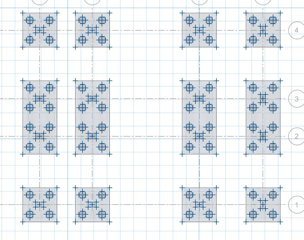
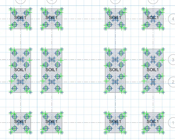
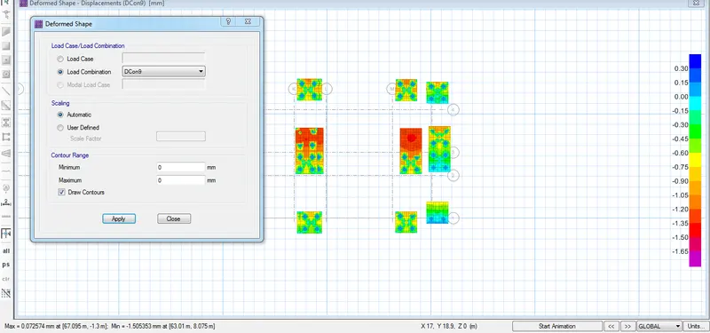
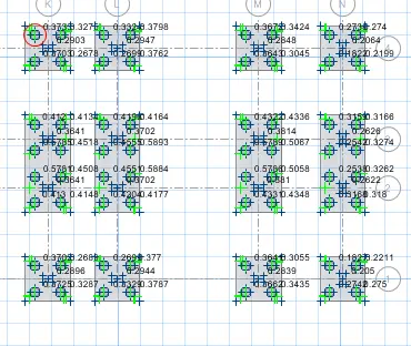
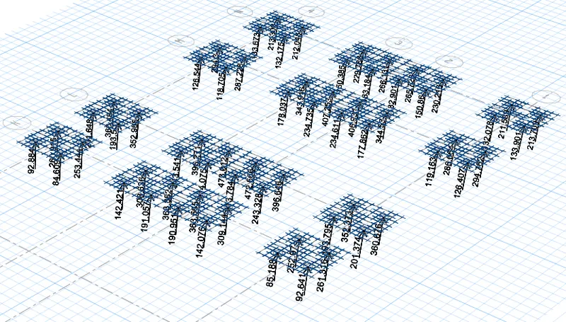
reaction force is less than pile capacity,hence ok.
- define the design strip.
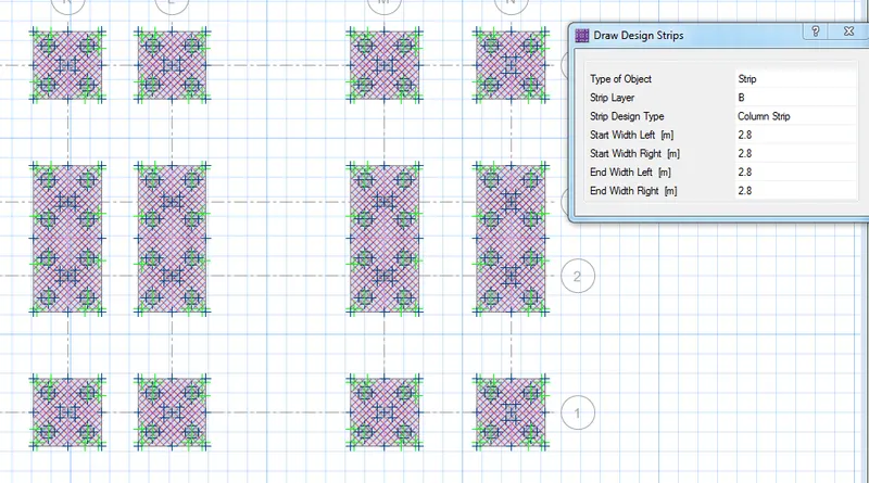
- run analysis again and show slab design.
- check for requirement and design the reinforcement.
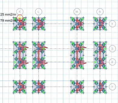
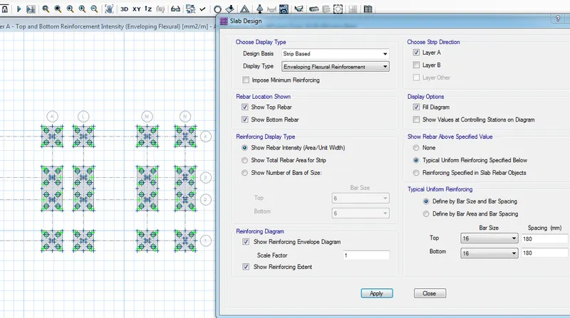
provide 16mm dia bar @180mmc/c for both top and bottom reinforcement.
RESULT:
- Etabs model for the two blocks on either side of the expansion gap is analysed.
- Framing plan for typical floor is obtained.
- Column reinforcement is provided.
- Beam reinforcements for ground floor is provided
- Foundation details illustrating the pile & pile cap reinforcement using SAFE.
- Tie beam details connecting the pile caps.