Project 2_Design & Analysis of a Hostel building at Guwahati, Assam
AIM: ANALYSIS AND DESIGN OF HOSTEL BUILDING AT GUWAHATI, ASSAM BY USING ETABS MODEL AND SAFE MODEL
ANS:
- GIVEN:
- Location – Guwahati, Assam
- Function – Hostel block in an academic institute
The walls will be made of AAC blocks. Other loadings are to be calculated as per the architectural drawings.
The buildings rest on type 3 soil. Piles of length 10 meters and 500 mm diameter with a load carrying capacity of 280 KN is to be used.
The ground floor level will be at the height of 2 meters above the existing site level to avoid flood water enter the building.
M25 grade of concrete with Fe500 for longitudinal reinforcement and Fe 415 for shear reinforcement will be used.
The following design IS codes will be required for reference:
- IS 875 part 1
- IS 875 part 2
- IS 13920
- IS 1893
- IS 2911 part 2
- IS 456
- SP 34
- DATA:
- There are two types of foundations:
- Shallow foundation
- Deep foundation
- Shallow foundations are of 5 types they are :
- Isolated footing
- Combined footing
- Strip footing
- Strap footing
- Raft or mat footing
- Deep foundation is of 2 types:
- Pile foundation
- Drilled shaft or caissons
- Pile foundation:
- A pile foundation is a kind of deep foundation and its used in a place where the water table of soil is above or if the soil is clayey type
- pile foundation is a type of slender column below the soil which is used to transfer the load at desired depth either by end bearing or skin friction
- the depth of the pile is decided by the depth of the hard strata
- each pile will have a pile cap for connecting the column
- PROCEDURE:
- Step1:
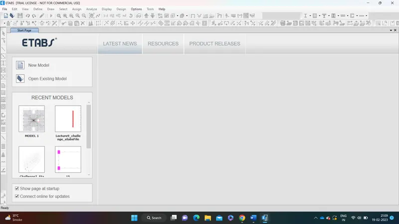
- Open the ETABS software by double-clicking on it
- Then click on the new model option which is on the left side of the screen
- Step2:
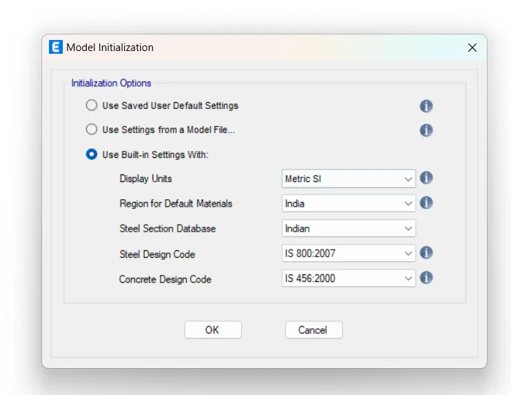
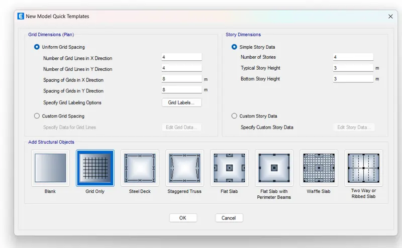
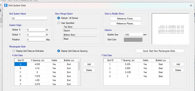
- after clicking on the new model the model initialization dialogue box will open
- select the use built-in setting with
- set the unit as metric database as Indian, steel code book as IS 800:2007, and concrete design code as IS 456:2000
- then click ok
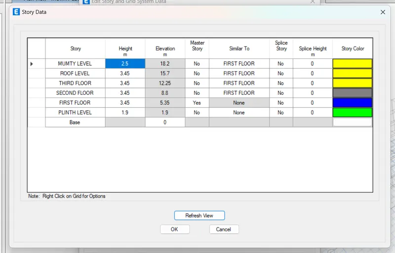
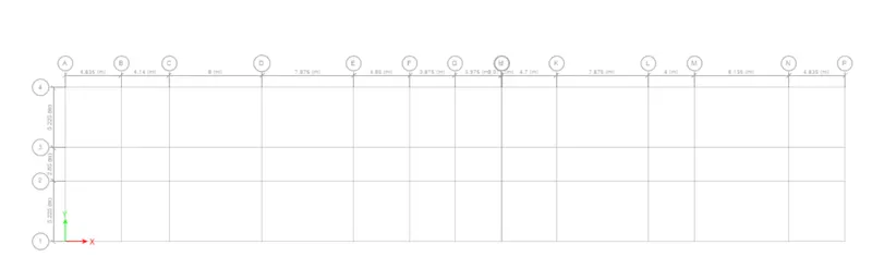
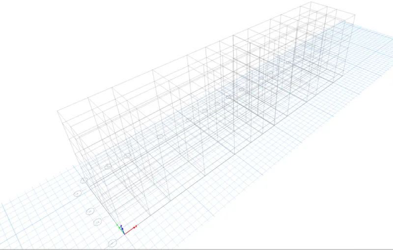
- step 3:
- after completing all the settings define the material and define the section for the column, beam, and slabs
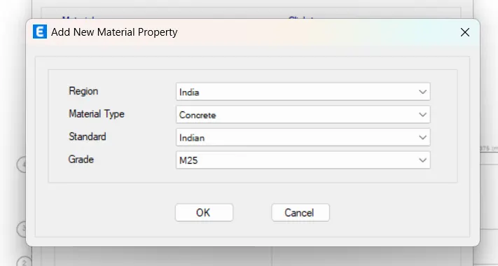
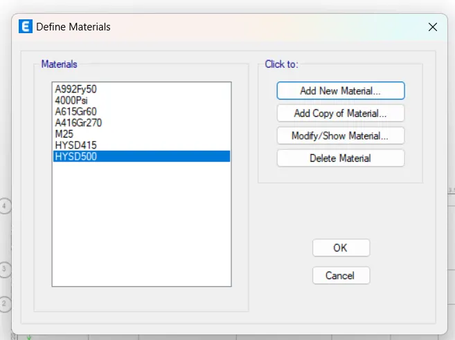
- click on define and select the material properties
- click on the new material to create a new material
- select the required properties of the material
- region as india, material type as concrete, standard as Indian, grade as M25
- Then click ok
- Step4:
- Click on the new material to create a new material
- Select the required properties of the material
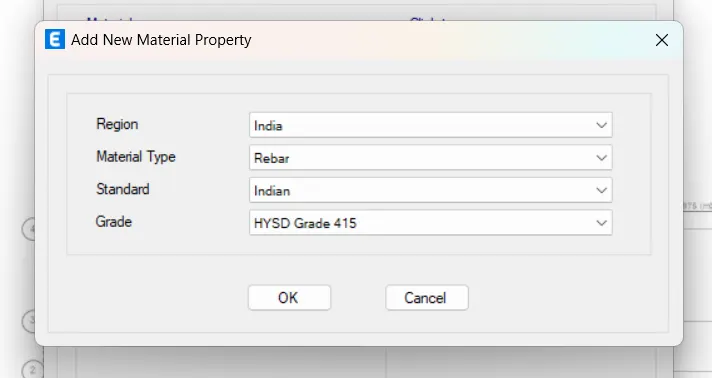
- Region as india, material type as rebars, standard as Indian, grade as HYSD grade 415
- Then click ok
- Step5:
- Click on the new material to create a new material
- Select the required properties of the material
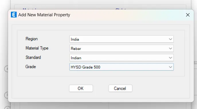
- The region as India material type as rebars, standard as Indian, grade as HYSD grade 500
- Then click on ok
- Step11:
- to define a section properties
- click on the define then click on the section properties then select the frame section
- after selecting the frame section
- click on the add a new property to create a new frame section
- select the rectangular concrete for the column then click on ok
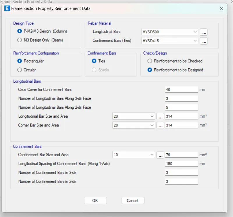
- after clicking on ok the frame section property data dialogue box opens
- change the property name to column 450x650 change the material as M30 change the dimension
- click on the modify show rebar to get more
- change the longitudinal bars to HYSD 500
- change the confinement bar to HYSD 415

- Step 12:
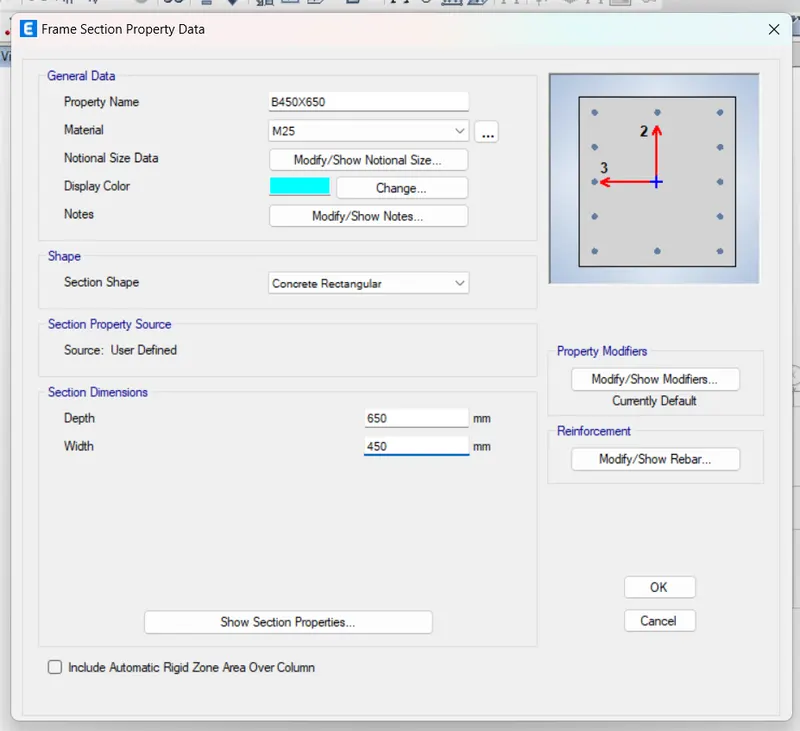
- Select the rectangular concrete for the beam then click on ok
- After clicking on ok the frame section property data dialogue box opens
- Change the property name to beam 400x650 change the material as M25 change the dimension
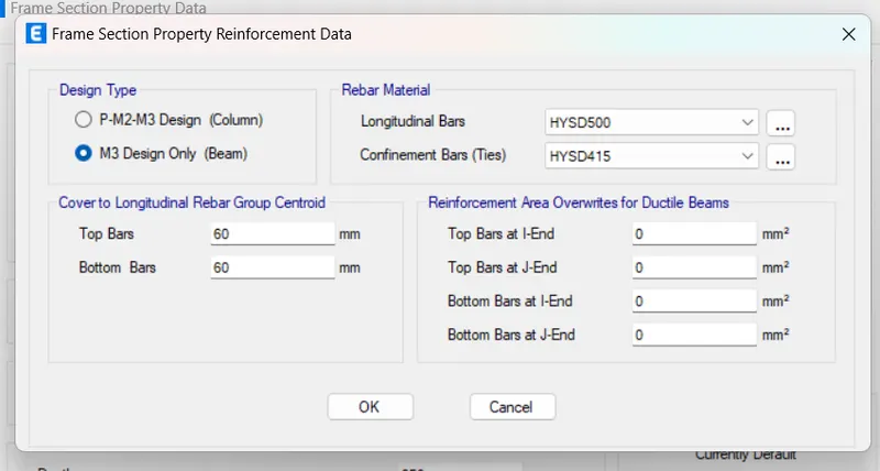
- Click on the Modify
- Step 8:
- After opening the modify then this dialogue box opens
- Select the M3 design only (beam)
- Then change the longitudinal as HYSD 500 and confinement bars as HYSD 415
- Then click on ok
- Step9:
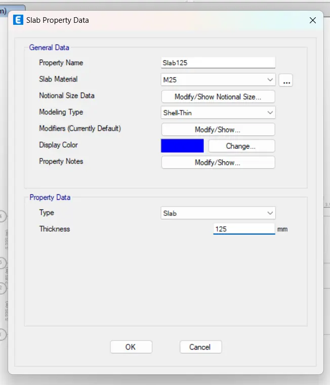
- To create slab, click on the define then select the section properties then click on slab section
- After selecting slab section, the slab properties dialogue box opens
- Then click on the modify show properties to change the properties
- Change the properties name as slab 125mm change the slab material as M25 and change the slab thickness
- Then click on ok
- Step10:
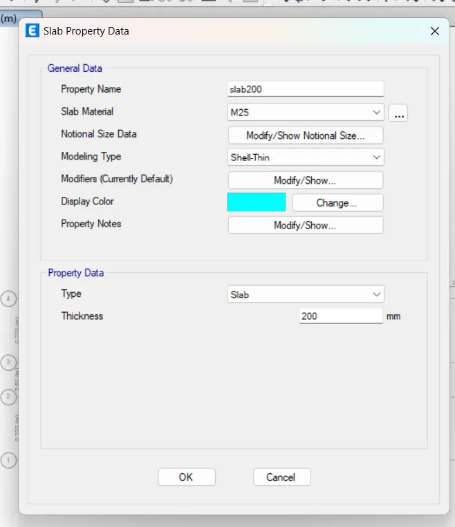
- Then click on the add new properties to change the properties
- Change the property name as slab 200mm change the slab material as M30 and change the slab thickness
- Then click on ok
- This slab is used for the slab stairs
- Step11:
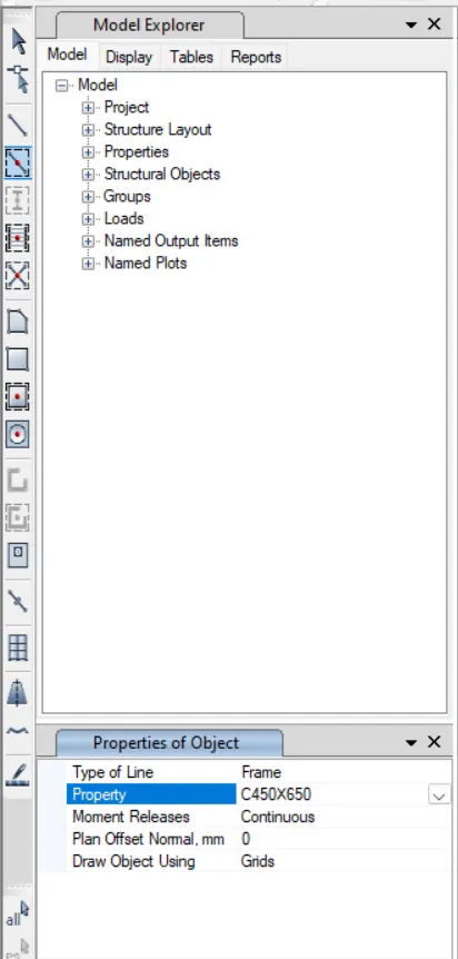
- Draw the column at the junction of the grid line
- Click on the quick draw column icon in the tool bar
- Step12:
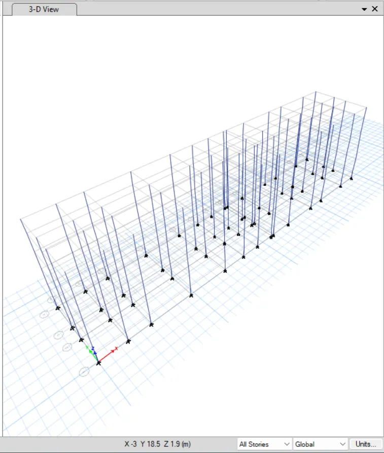
- After drawing all the column then change its orientation
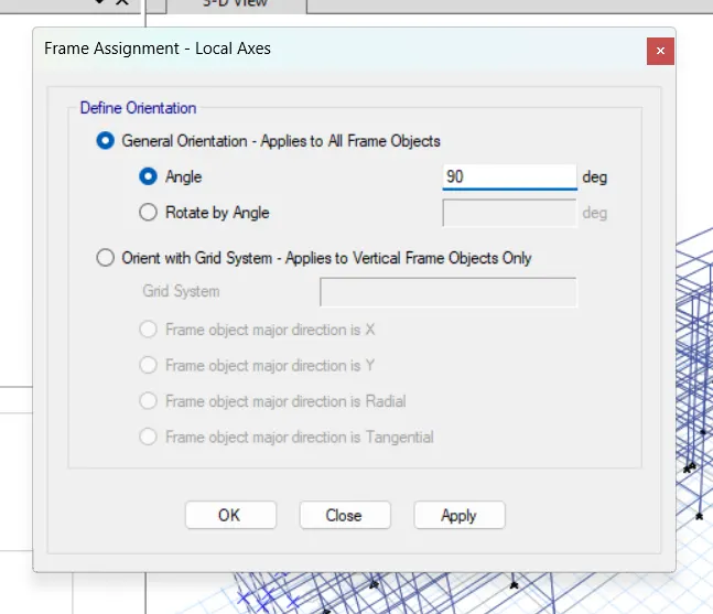
- Go to the assign then go to the frame then go to the local axes
- Then the frame assign ment dialogue box opens
- Then select the rotate by angle and give the angle as 90 degree
- The column will orient
- Step13:
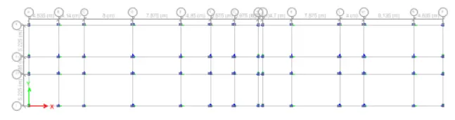
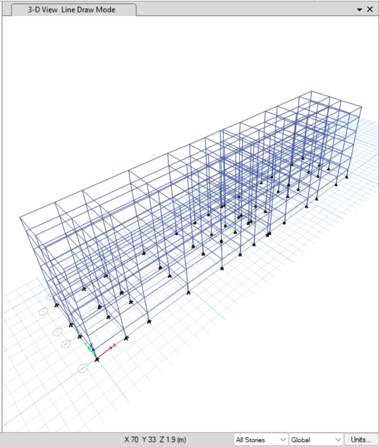
- This is the how the column placement after changing the orientation of the column
- Make sure the required column is oriented correctly
- Steps14:
- Draw the beam along the junction of the grid lines
- Click on the quick draw beam/column icon in the tool bar
- Select the grid in which you required the beam
- Select grid where the column connection occurred
- Step15:
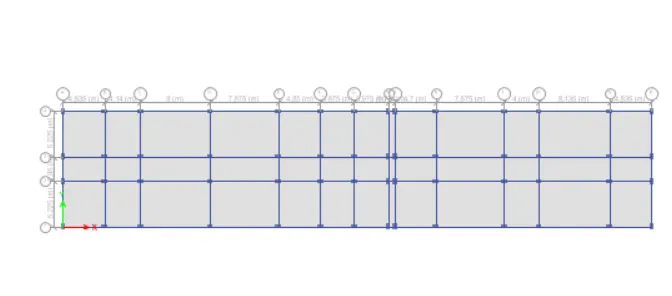
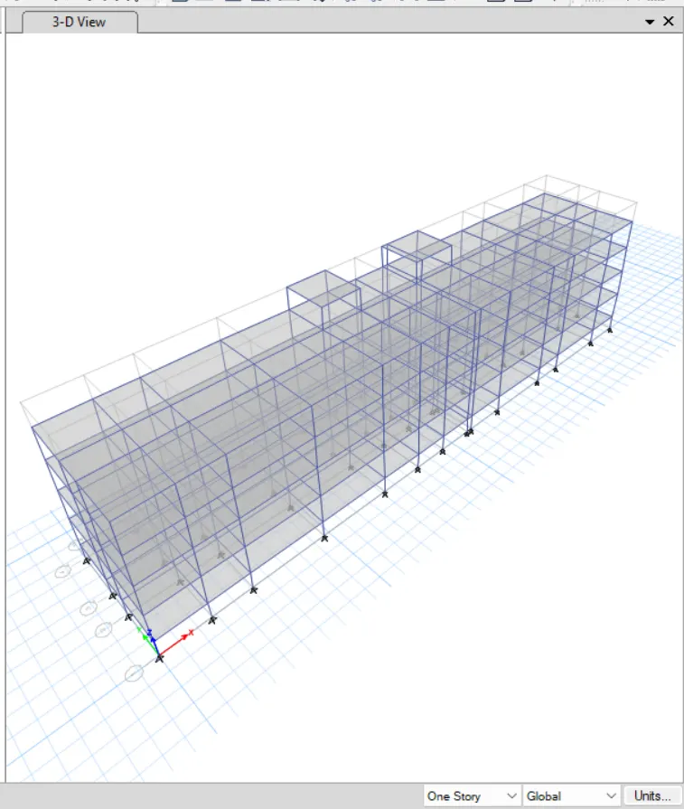
- To create a slab
- Click on the define then select the section properties then click on slab section
- After selecting slab section the slab properties dialogue box opens
- Then click on the slab 200mm for stair and 125mm for building
- This is the how the slab will look like after assigning the slab properties
- Steps16:
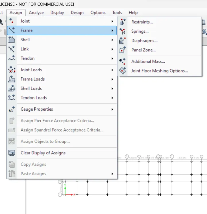
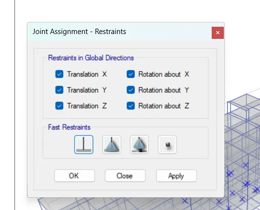
- Assign the joint to the base
- First select the base point then go to assign then click on joint
- Then click on restrained
- Steps17:
- After selecting the restrained then joint assignment dialogue box opens
- Then select the fixed joint then click apply
- Then click ok
- Steps18:
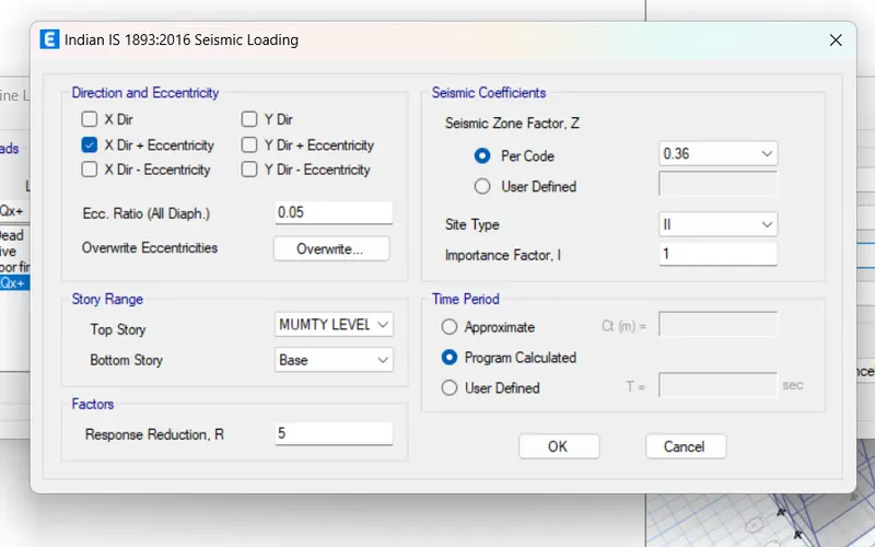
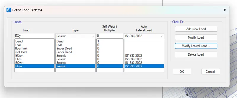
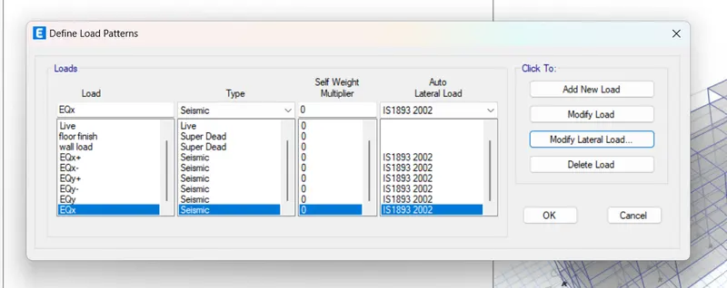
- To define the load pattern
- Click on the define then click on the load pattern
- Add the load pattern
- Dead load, live load wall load, seismic load in both x and y direction
- Mention the code book for seismic load
- Modifying lateral loads for EQx
- Steps19:
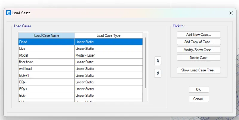
- To define the load cases
- Click on the define then click on the load cases
- Load cases are assigned by the software only
- Click on ok
Step24:-
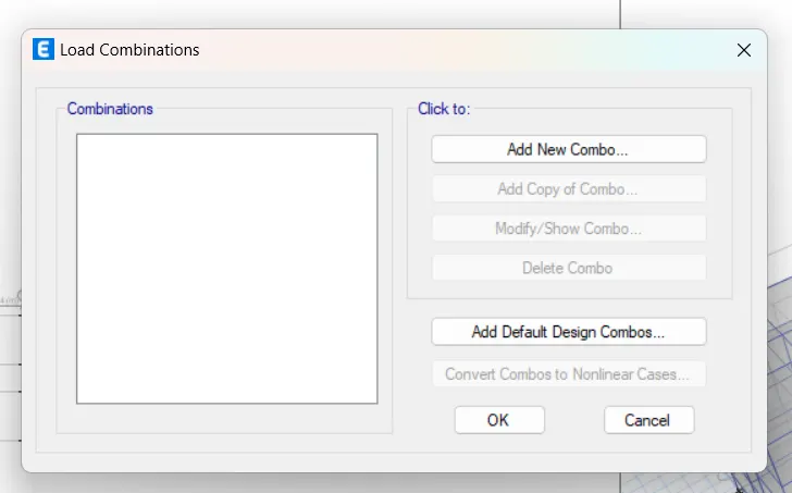
- To define the load combination.
- Click on the define then click on the load combination.
- Select the default combination.
- Then click on the concrete frame design then click on convert to user combination.
- Then click ok
Step25:
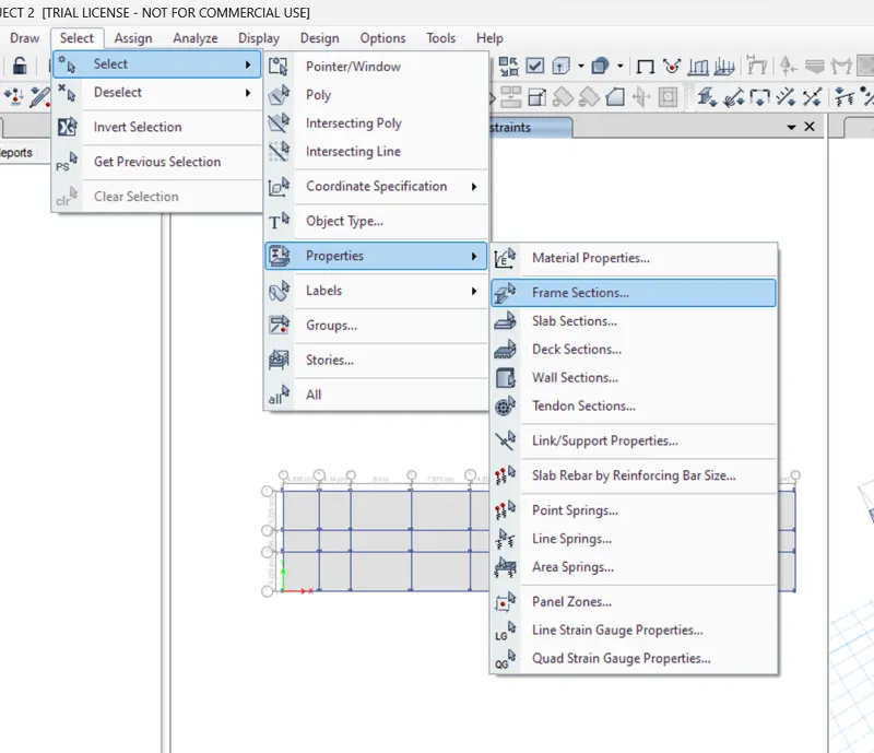
- To select the frame selection
- Click on select then click on select then click on properties then select the frame section.
- Then select all the beams.
Step26:
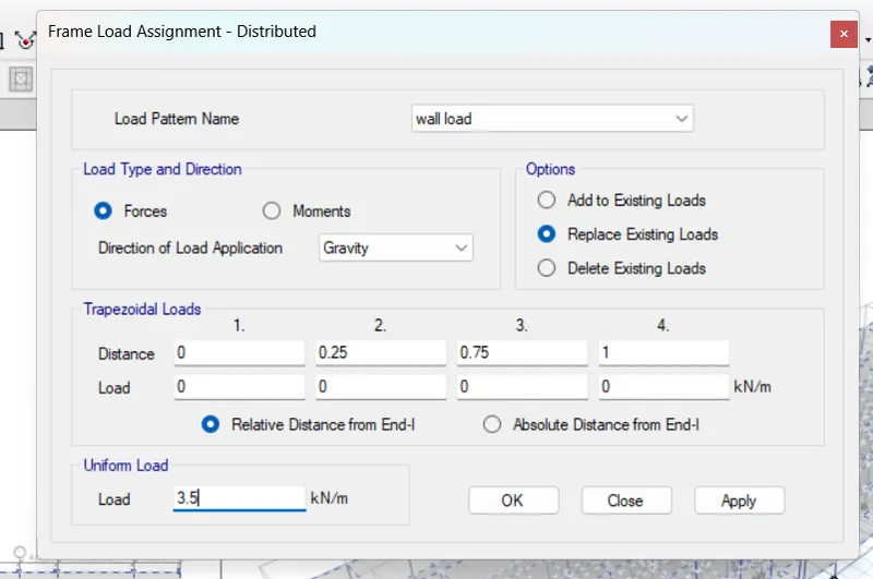
- Assign the loads for the frame element
- Click on the assign then click on the frame load and then click on the distributed
Step27:
- To select a beam section.
- Then select a assign then go to the shell load then selected a distributed
- Select the load pattern as a wall load
- Then take a uniform load as a 3.5 KN/m
- Then click on apply then click on ok.
Step28:
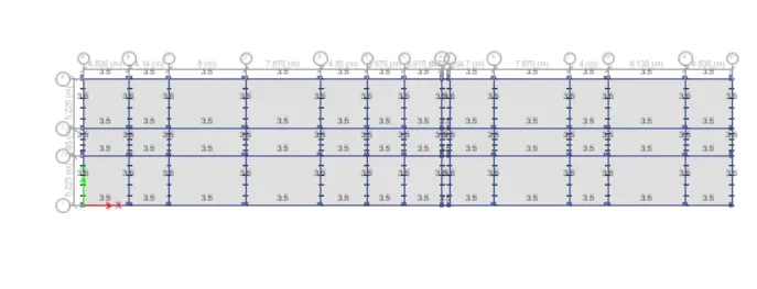
- After applying the 3.5 KN/m loads.
- The load assigned to the beam is shown as below.
Step29:
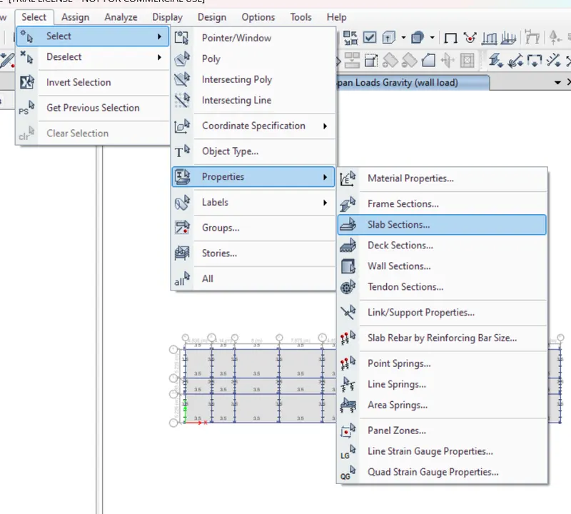
- To select the slab section.
- Click on select then then click on select then click on object type then select the floor sections (All the slabs are selected).
Step30:
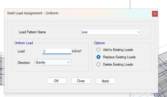
- To assign the loads of the slab.
- Click on the assign then click on the shell load then click on uniform
Step31:
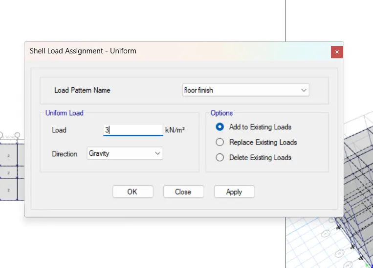
- Select the load pattern as live
- Then take a uniform load as a 2 KN/m
- Then click on apply then click on OK
Step32:
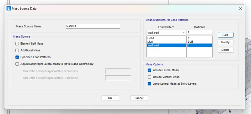
- To define the mass source.
- Click on the define and then click on the mass source.
Step33:
- After selecting the mass source then mass source data dialogue box opens.
- Check only the specified load pattern
- Select the load patterns of dead load of 1 multiplier, live load of 0.25 multiplier wall load of 1 multiplier.
- Then click on OK.
Step34:
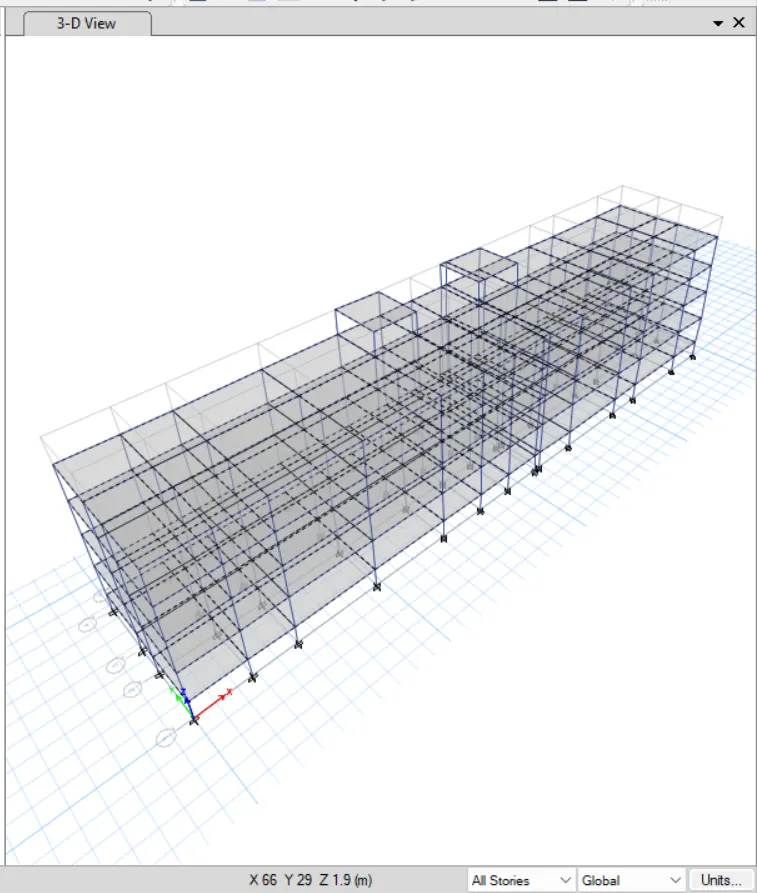
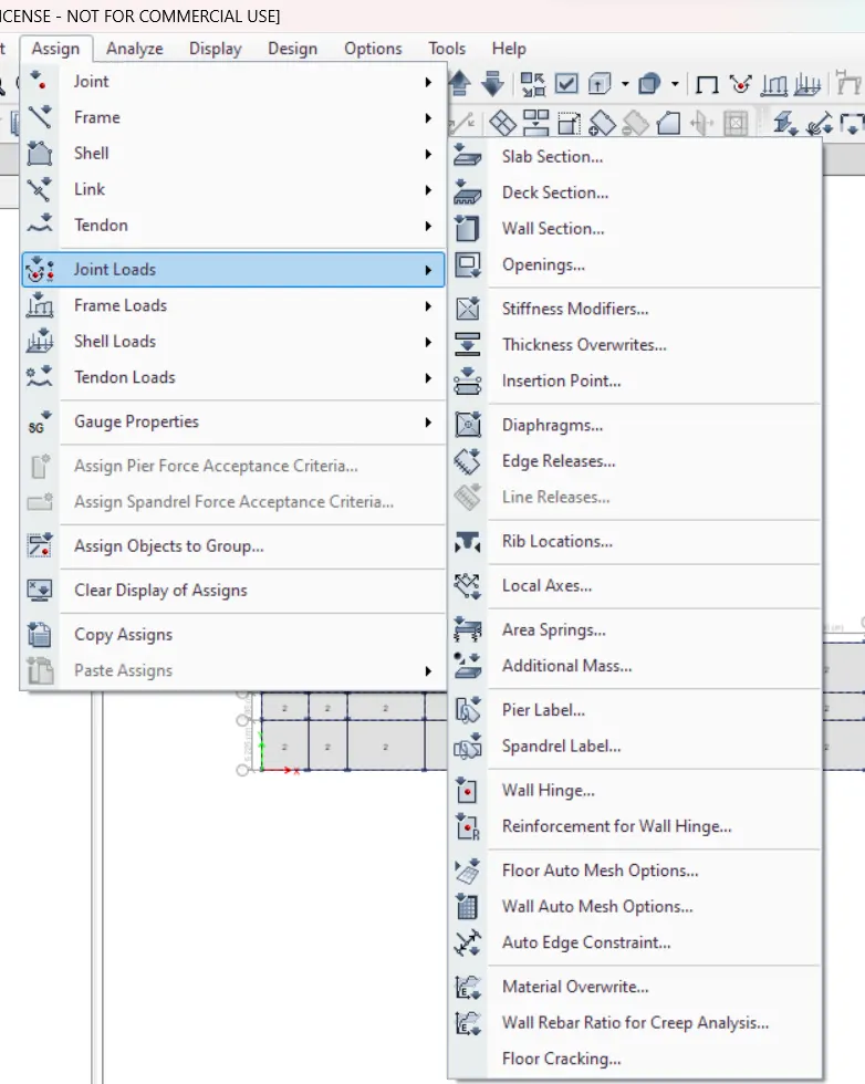
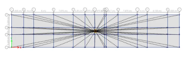
- To provide the diaphragm
- First select the slab section
- Clicks on assign then click on shell then click on the diaphragm.
Step35:
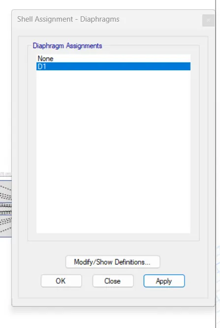
- The diaphragm dialogue box opens
- Then select the diaphragm assignment as DI
- Then click on apply then click on OK
Step36:
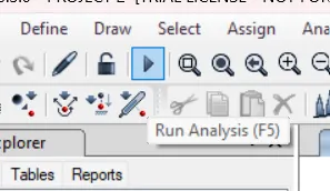
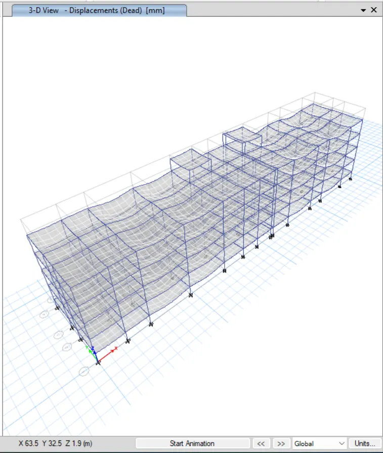
- At last run the analysis by clicking the run analysis button or by clicking F5
- Give a time for analysis then it will give a result of it.
Step37:
- After analysis then click on the concrete frame design
- Wait for some times it will give the correct result.
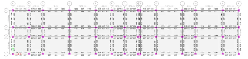
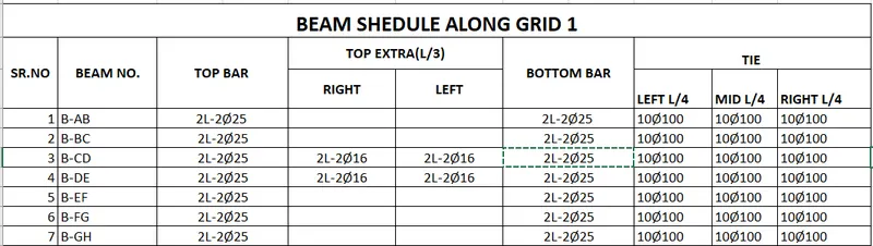
This is the how it looks like after the concrete design complete and it’s a longitudinal reinforcement for the beams.
Step38:
- Now I’m considering 7 Span continuous beam which is at along the grid (1- A TO 1-H)
- Here the maximum longitudinal reinforcement at bottom is 637 mm^2 (more than 637 mm^2 reinforcement is also present but we will give extra reinforcement for that region.)
- Here the maximum longitudinal reinforcement at top is 1278 mm^2
This is the longitudinal reinforcement details from ETABS
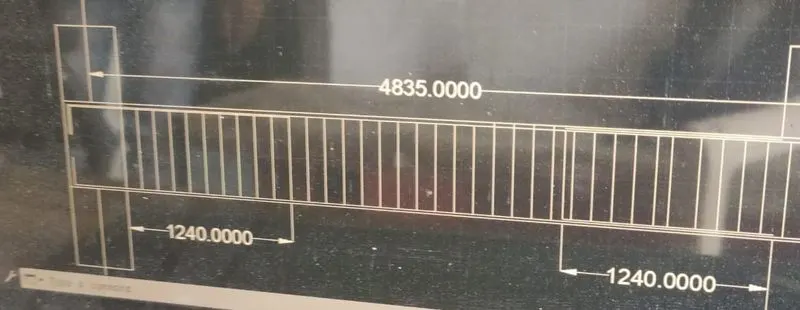
This is the Shear reinforcement details from ETABS
AUTOCAD DRAWING
Now I’M Considering 7 span continuous beam which is at along as grid (1-A TO 1-H)
This is for the grid 1-A to 1-B


Step39:
Column
Special confining reinforcement from IS 13920-2016(Clause 8.1)
IS 13920:2016
From the IS 13920:2016 mentioned about the lo, confinement spacing and amount of confinement rebar.


Lo not less than
- Larger column dimension
- 1/6th of the clear span of the column
- 450 mm
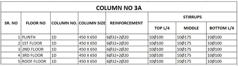
Here the larger column dimension is 650 mm
In the 1/6th of clear span
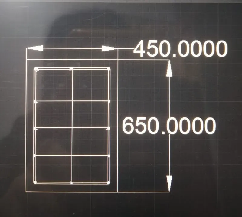
- Column size is given as 450x650mm.
- In this I’m considering first floor height which is a 3.45 m
- The height is given from the Centre of the column to the center of the other column
- We have to deduct half of the beam depth
- Deduct the 325mm above and below because the depth of beam is 650mm and height of the column as 2800
- 1/6 *2800 = 466mm
Consider lo = 650 mm
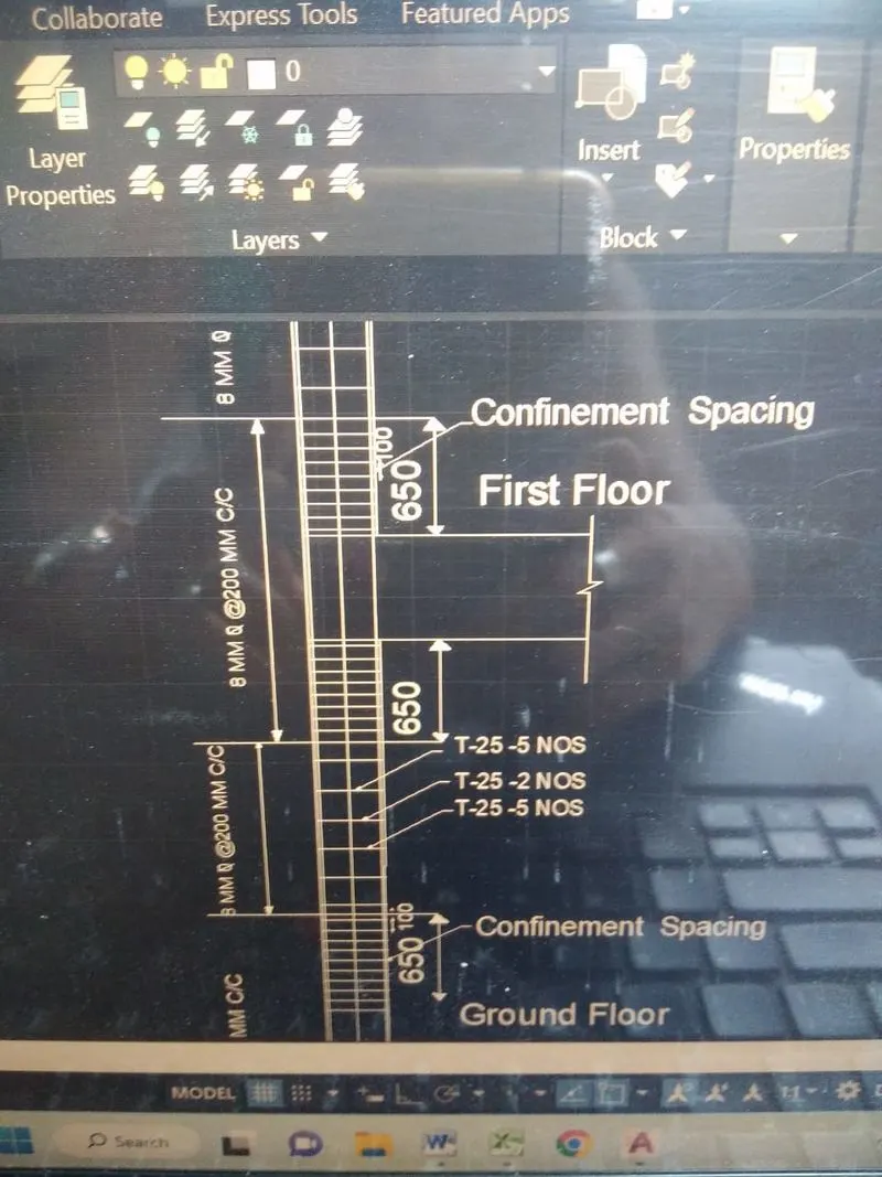
Confinement spacing
Confinement spacing not more than
- ¼ of smaller column dimension
1/4 *450 = 112.5
- 6 times dia of the column
6*8 = 48
- 100 mm
Use 8mm dia at 100mm spacing at the confinement area.
Use 8mm dia at 200mm spacing at the midspan.
These is the longitudinal reinforcement details from ETABS
AutoCAD Drawings:-
This is the cross-section of the column.
Exporting the drawing file from the ETABS TO SAFE.
Step40:
- After the completion of concrete design and AutoCAD drawings.
- Then export the ETABS file to the SAFE file
- Click on the file then go to the export then go to the story as SAFE V12.F2K File.
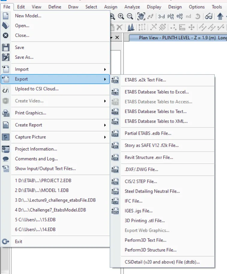
Step41:
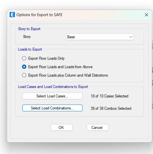
- After that option to export to safe dialogue box opens.
- Then select the export floor load and load from above.
- Then click on the load cases then select all then click OK
- Then click on the load combination then select all then click OK
- Click on OK
- Now the file is exported.
Data required for the safe analysis and design
Column size = 650x450 mm
Load carrying capacity =280 KN
Step42:-
- Open the safe software by double clicking on it.
- Click on file then click on import
- Then click on SAFE.F2K file.
- Select the file where you saved then click an open.
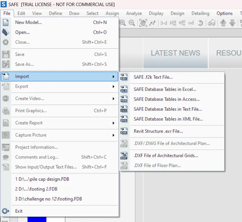
Step43:-
- This is the how the exported file from ETABS To SAFE is look like
Step44:-
- To see the loads assignment
- Click on display then select show load assign
- Then click on Joints.
Step45:-
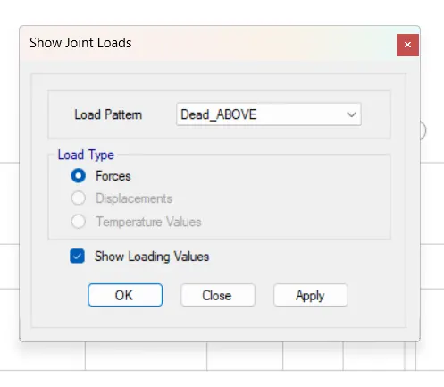
- After selecting the joints show joint loads dialogue box opens
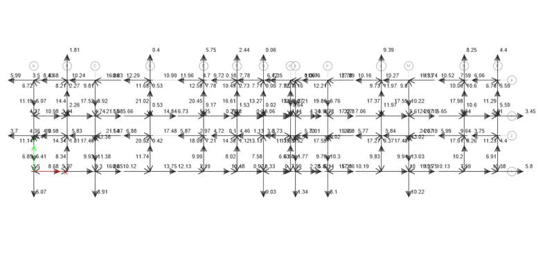
- Then select the dead above option in the load pattern.
- Then click apply and then click OK
- The sand shot of the dead above load is inserted below
Step46:-
- After selecting the joints show joint loads dialogue box opens
- Then select the live above option in the load pattern.
- Then click apply and then click OK
- The sand shot of the live above load is inserted below.
Step47:-
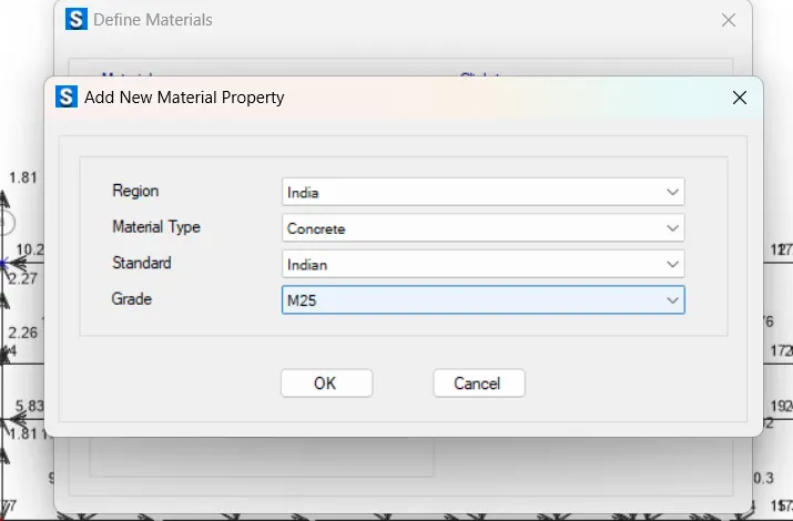
- Click on the define then click on the material property
- Then click on the add new Material
- Then create the M-25 concrete as shown
- Then click on OK
Step48:
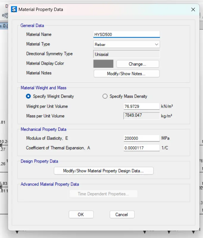
- Then click on the add new material
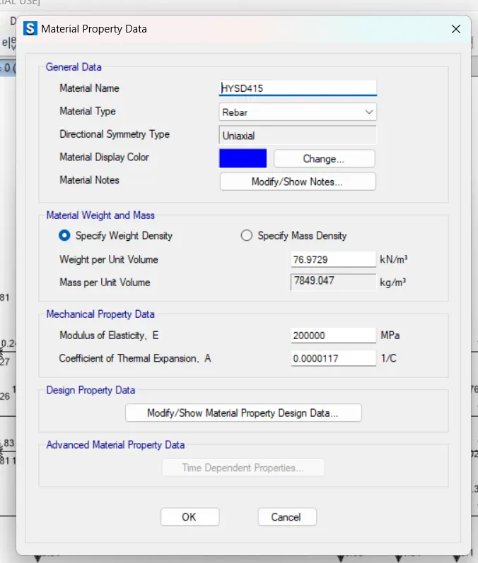
- Then create the Fe 500 steel as shown.
- Then click on OK.
Step49:
- Then click on the add new material
- Then create the Fe 415 steel as shown.
- Then click on OK.
Step50:
- These are the defined material for the safe model
Step51:-
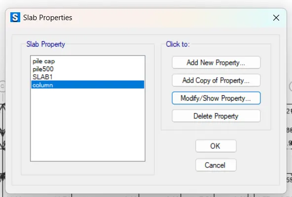
- Click on the define then click on the section properly.
- Then click on slab section.
- Then click on the add new material
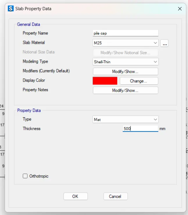
- Then create the Pile cap 500mm as shown.
- Keep the property data type as a Mat
- Then click on OK.
Step52:-
- Then click on the add new material
- Then create the Pile cap 500mm as shown.
- Keep the property data type as a Stiff
- Then click on OK.
Step53:-
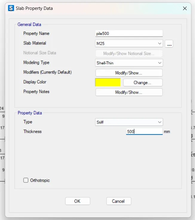
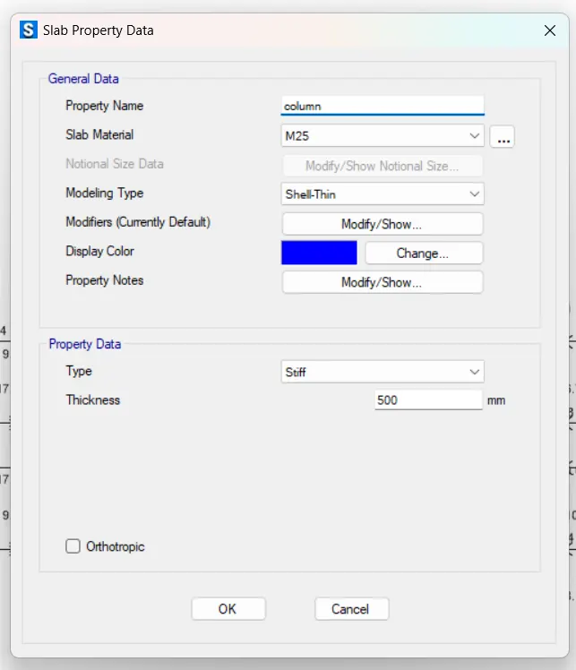
- Then click on the add new material
- Then create the Stiff 500mm as shown.
- Keep the property data type as a stiff
- Then click on OK.
Step55:-
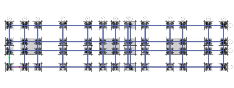
- This is how the model looks like after the placing of the pile caps, piles, stiff column and tie beam.
- This is the tie beam extrution.
Step56:-
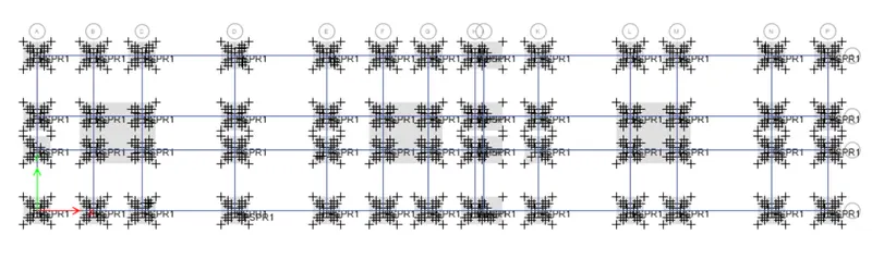
- Assign the spring to the piles by selecting the middle points in the piles.
- Click on the assign then click on the joints
- Then click on the spring
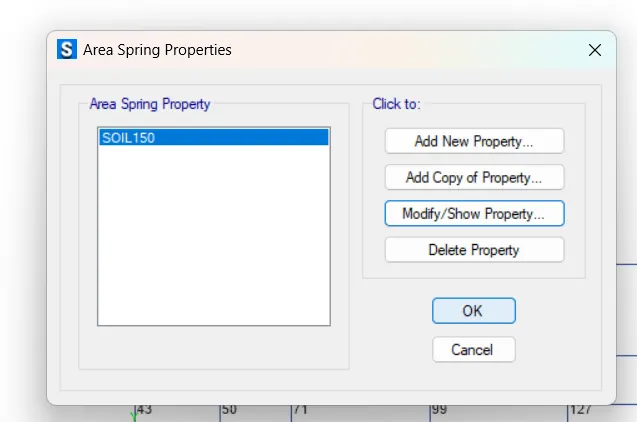
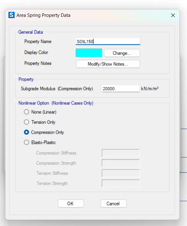
Step57:-
- After clicking springs then joints assignment dialogue box will opens then click on modify/show deformation.
- Then click on add new property
- Then the point spring property data dialogue box opens.
- Enter the point screen as 490872.5 KN/m
- Then click on compression
- Then click on OK
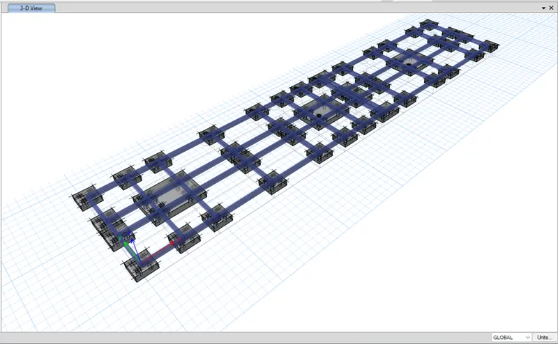
Step58:-
- This is the how the piles look likes after the assigning the spring joints to it
Step59:-
- In this step I’m getting a warning message from the software when I click Run analysis.
- The warning message is about the mesh
- So provide the proper mesh to the footing
Step60:-
- Create a mesh by using a draw design strips
- First draw the reference lines then draw the design strips along A from left to right direction
- Draw the design strips along B from bottom to top direction
Step61:-
- Go to the analyze then go to the automatic mesh setting for floor
- Before it is in general mesh then change it into rectangular mesh and provide the approximate maximum size as 0.1
Step62:-
- After making all the changes then click on Run analysis.
Step63:-
Check needs to be performed in SAFE analysis
Individual pile capacity under service load
- Here check the reactions of the piles
- Select the reaction icon then select the service combo, the load combination should be combo
- Then click on OK
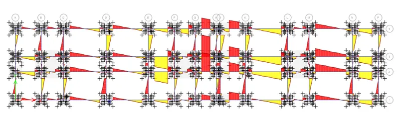
- The maximum load is taken by the piles are 177.59 KN ALMOST 200 KN
- The minimum load taken by the piles are 137.31 KN
- These loads snap shot is inserted below
- Hence safe
Settlement under service load
- This is the deformed shape of the model
- The load is combo, then type of load is service combo
- The allowable deflection is 50mm but I’m getting the 0.42mm as the deflection value.
- Hence safe
Two way shear check (Punching shear)
- To check the punching shear just click on the show punching shear icon
- The maximum punching shear may go up to 0.9 or 0.95 but I’m getting the punching shear as 0.493 is minimum and 0.562 as maximum
- Hence it is safe
Flexural reinforcement design for footing slab
- Click on the show slab design then it shows the slab design dialogue box
- Make sure that the impose minimum reinforcement is selected and layer A and layer B are selected
- Then click on OK
- In this the top and bottom reinforcement are calculated by the software itself.
- The maximum reinforcement is required at the mid of the column, it is a 1317.12 mm^
Result:-
- Individual pile capacity under service load – the maximum load is taken by the piles are 177.59 KN almost 200KN, The minimum load taken by the piles are 137.31 KN- safe
- Settlement under service load -0.42 mm- safe
- Two way shear check -0.493 is minimum and 0.562 is maximum –safe
- Flexural reinforcement design for footing slab -1375.12mm^2
By using SAFE software we came to know that the pile foundation design is safe
This design is done according to the IS 2911 (part-2) code book and SP 34 code book
Hence the foundation design is safe
Hence the design and analysis of a hostel building at Guwahati, Assam is safe.