Project 2_Design & Analysis of a Hostel building at Guwahati, Assam
AIM
To create the entire design process of modelling, analysis , design and preparation of construction drawings using ETABS and SAFE software
INTRODUCTION
ETABS:
- ETAB or ETABS they mean the same. Its full form is extended three-dimentional analysis of building system.
- It is an engineering software product that caters to multi-story building analysis and design.
- ETABS offers a single user interface to perfom modelling, analysis, design and reporting.There is no limit to the number of modelling windows,model manipulation views and data views.
- Basic or advanced systems under static or dynamic conditions may be evaluated by using ETABS
- ETABS modelling is the genralization that multi-story buildings typically consist of identical or similar floor plans that repeat in the vertical direction.
- Modelling features that streamline analytical-model generation,and stimulate advanced seismic systems.
- Once modelling is complete,ETABS automatically genrates and assigns code-based loading conditions for gravity,seismic,wind and thermal forces
SAFE:
- CSI SAFE ( slab analysis by the finite elemnet method) is the best tool for designing concrete slabs and foundations
- SAFE provide easiness to engineer towards the safe design of structures with powerful tools like draw, analyze,design and detailing etc
- Lying out models is quick and efficient way with the user-friendly drawing tools, or user can import model from AutoCAD or loading conditions from other spftware,s like CSI ETABS and CSI SAP2000
PROCEDURE
STEP:1
- Open ETABS software
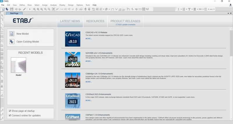
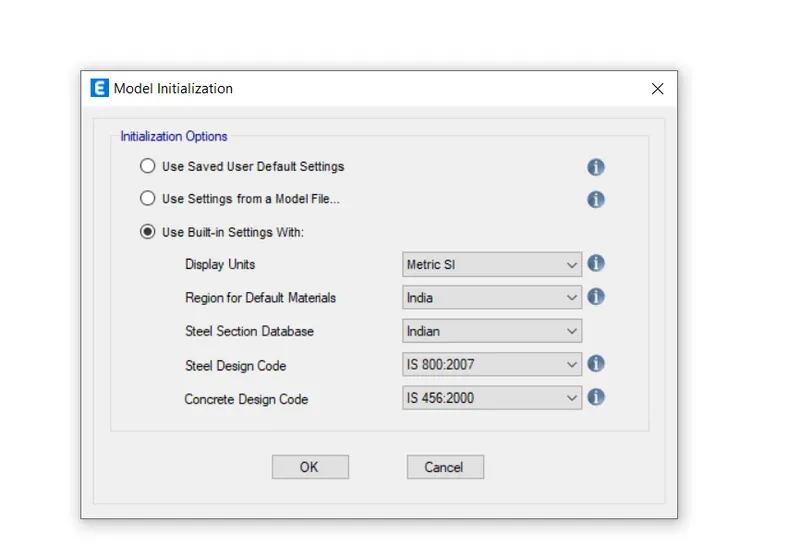
- Then click on the new model and choose use built-in setting with option
- Set the display unit as Metric SI or as per the requirement
- Then click ok
- New dialogue box will appear.
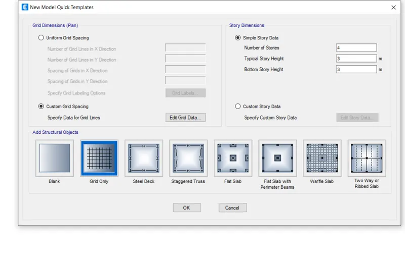
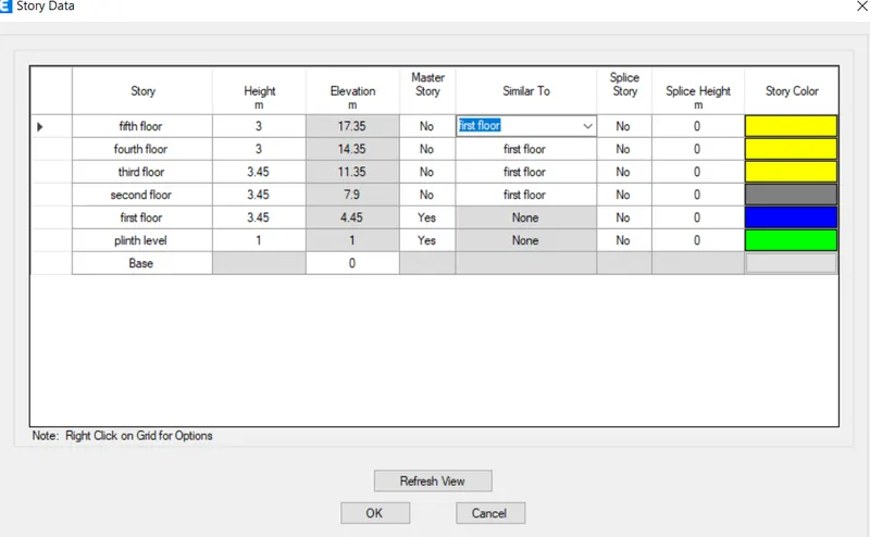
- Select the custom grid spacing and then select the edit grid data
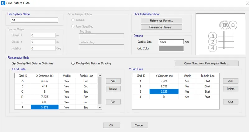
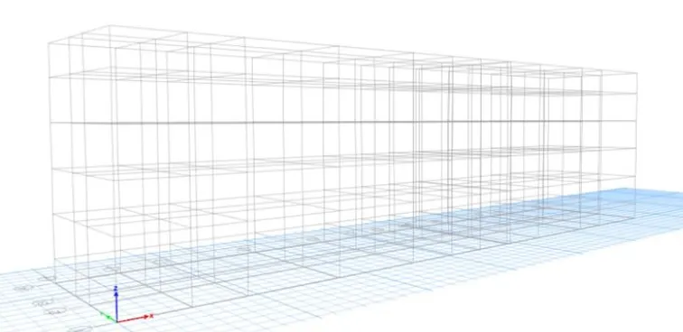
- Now determine the number of stories required
STEP:2
DEFINE MATERIAL PROPERTIES
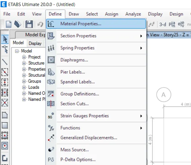
- Inorder to set the material first we need to go to the define option and there will be a drop-down list in that list there is another option called material properties
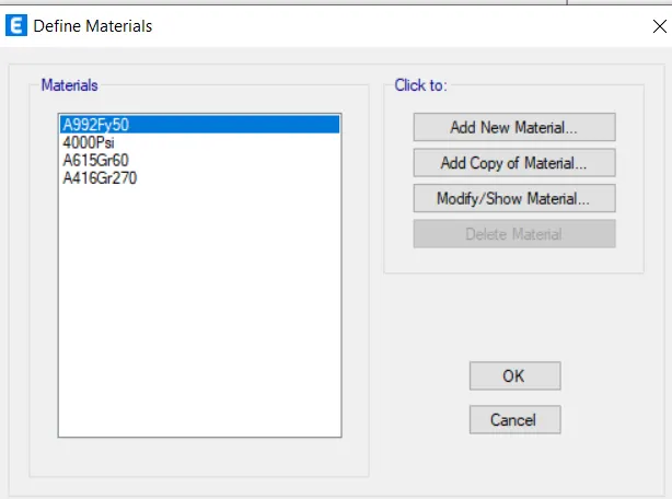
- After clicking on the material properety there will be another dialogue box named as define material, in that dialogue box just click on the option add new material
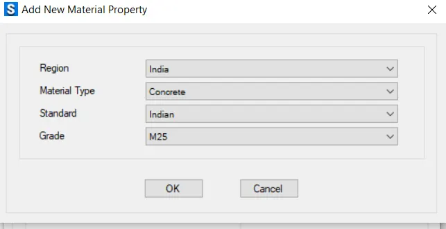
- New window will appear now define material type as concrete and grade as M25
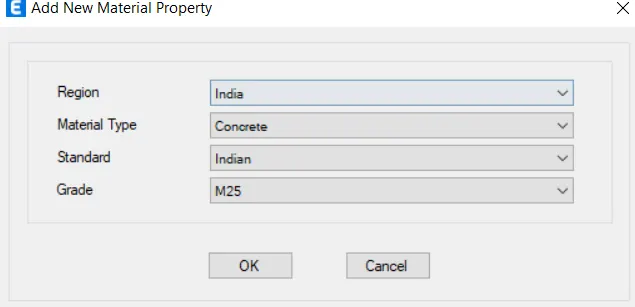
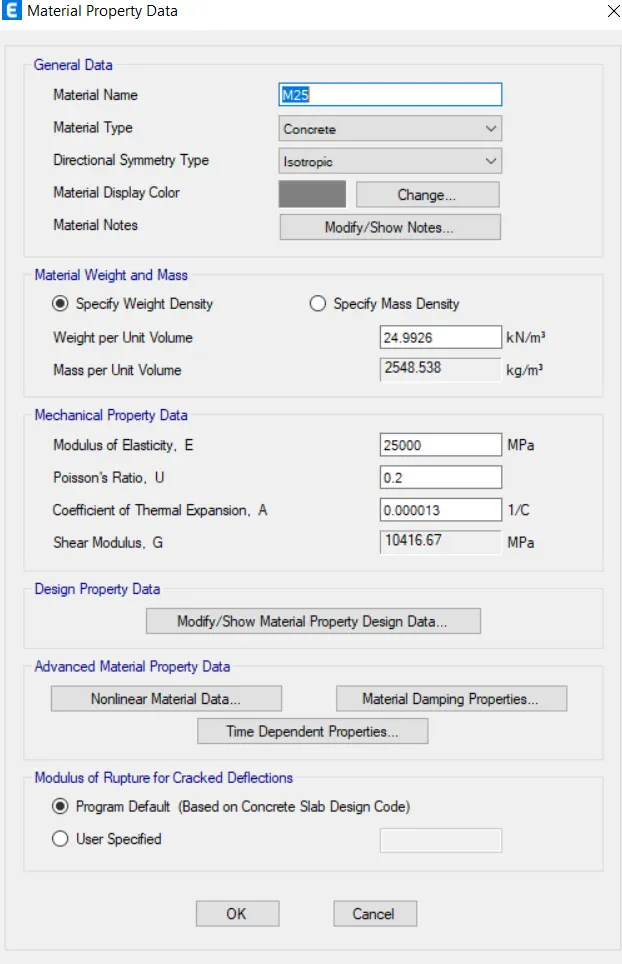
- Click ok
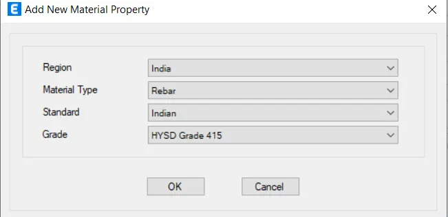
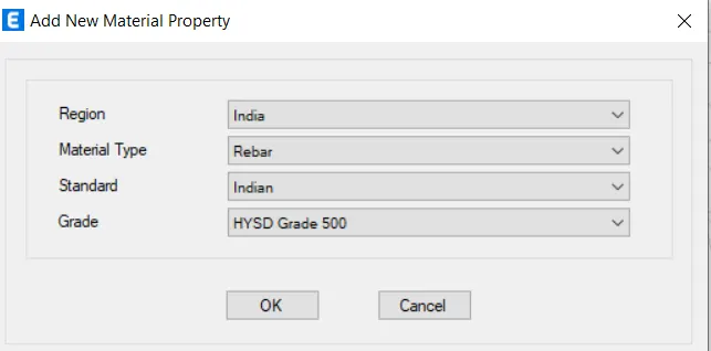
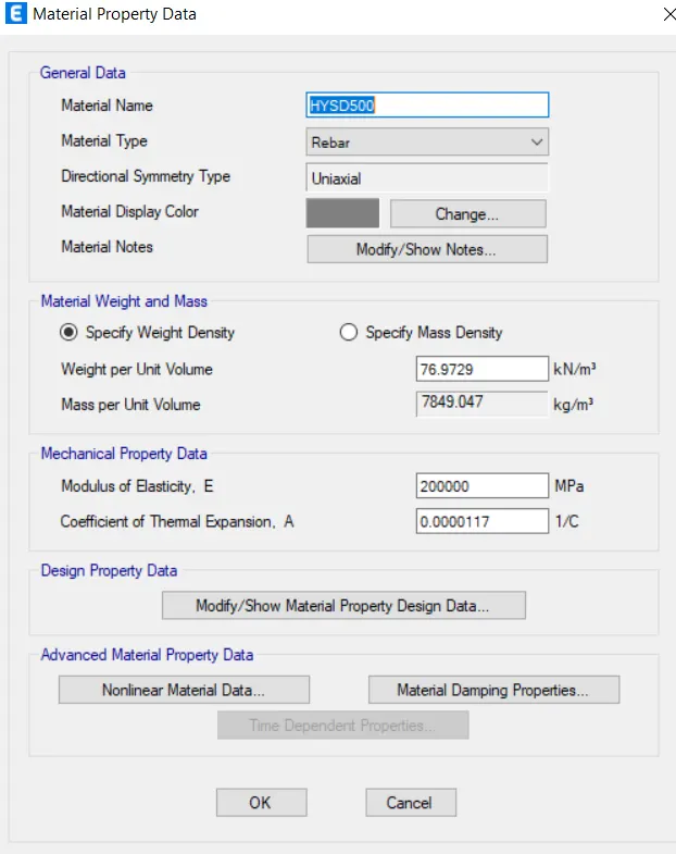
- Add new material property
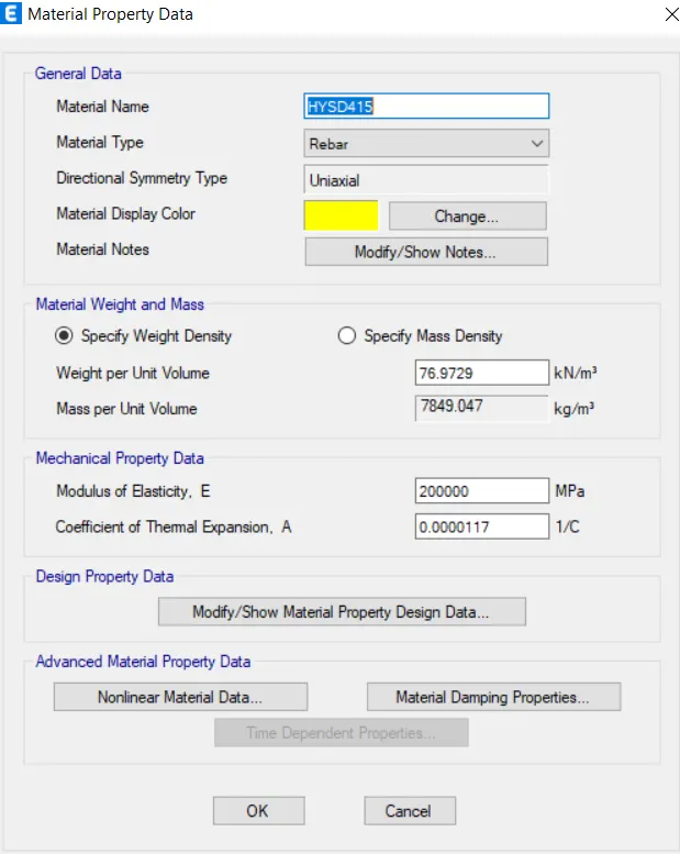
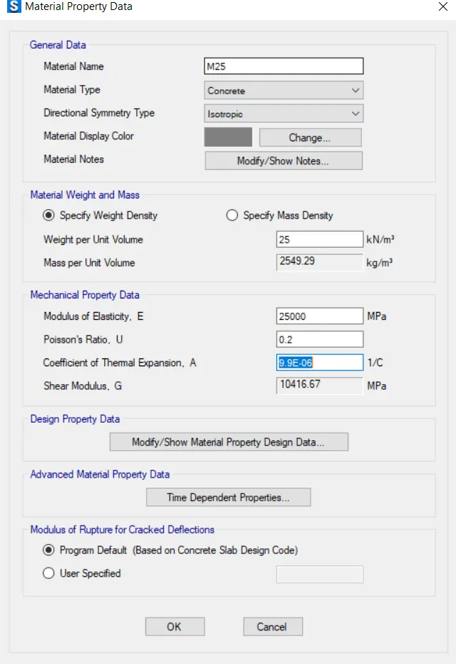
- New dialogue box will appear
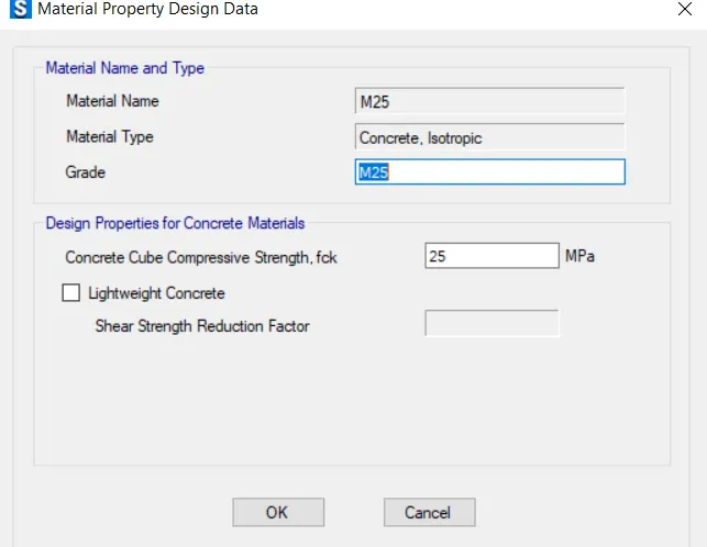
- Select materail type and grade
STEP:3
COLUMN
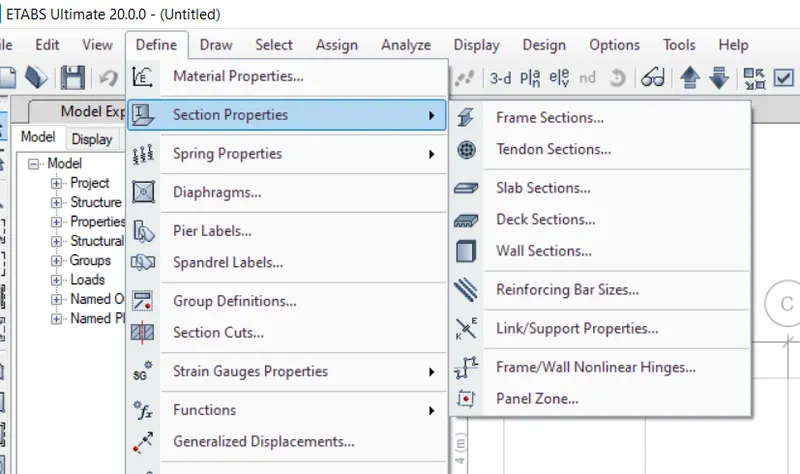
- Now we have to design the frame properties
- Go to the define tab there will be a drop-down list ,select section properties and from that select frame properties
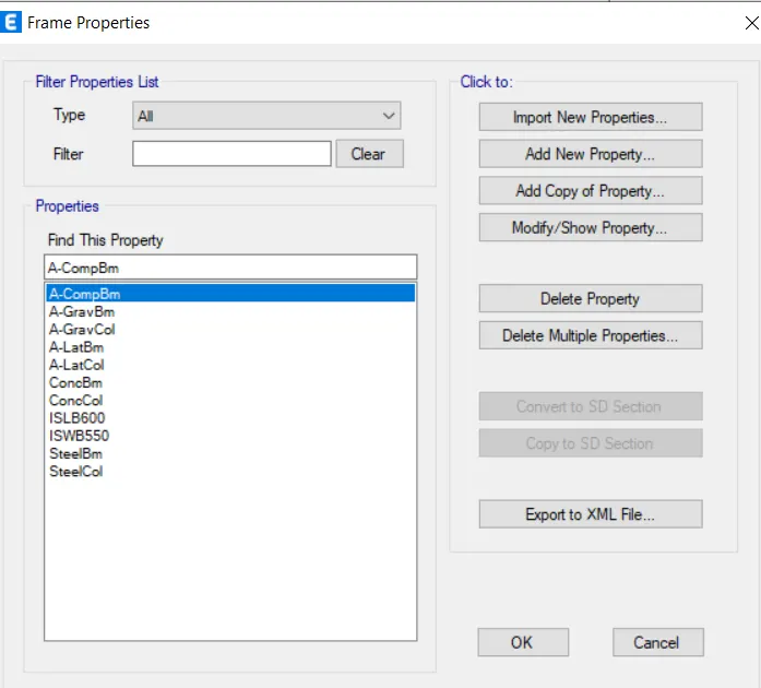
- A new dialouge box will appear ,in that select add new property
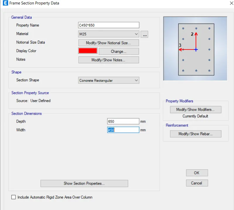
- Then select the rectangular concrete section,rename it C450*650
- Change the property as M25 and change the size as C450*650
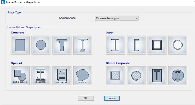
- After that another dialouge box opens
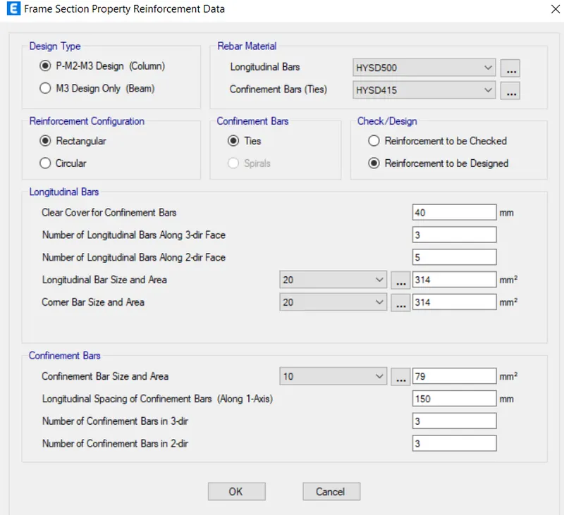
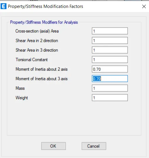
- Click on the modify/show modifiers, another dialouge box will appear on the screen fill all the relevant data
STEP:4
BEAM
- Now we have to design the frame properties
- Go to the define tab there will be a drop-down list ,select section properties and from that select frame properties
- A new dialouge box will appear ,in that select add new property
- Then select the rectangular concrete section,rename it B250*300
- Change the property as M25 and change the size as B 250*300
- After that another dialouge box opens
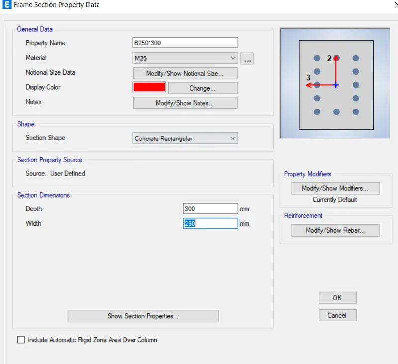
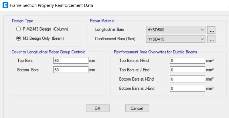
- Click on the modify/show modifiers, another dialouge box will appear on the screen fill all the relevant data
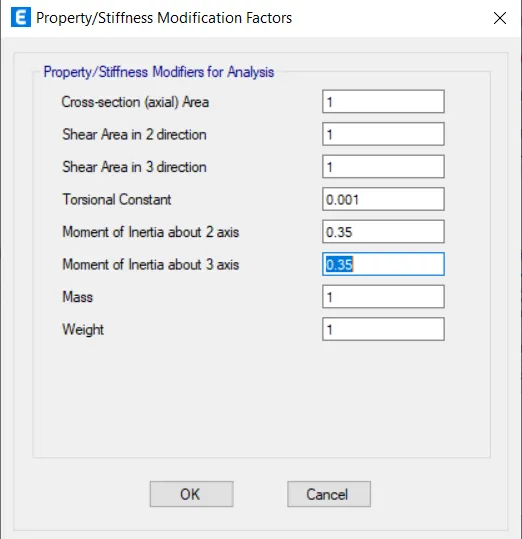
STEP:5
SLAB
- Then go to define select section properties from that select slab section
- New window appears
- Select add new property,nwe dialouge box will appear
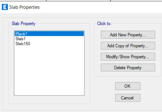
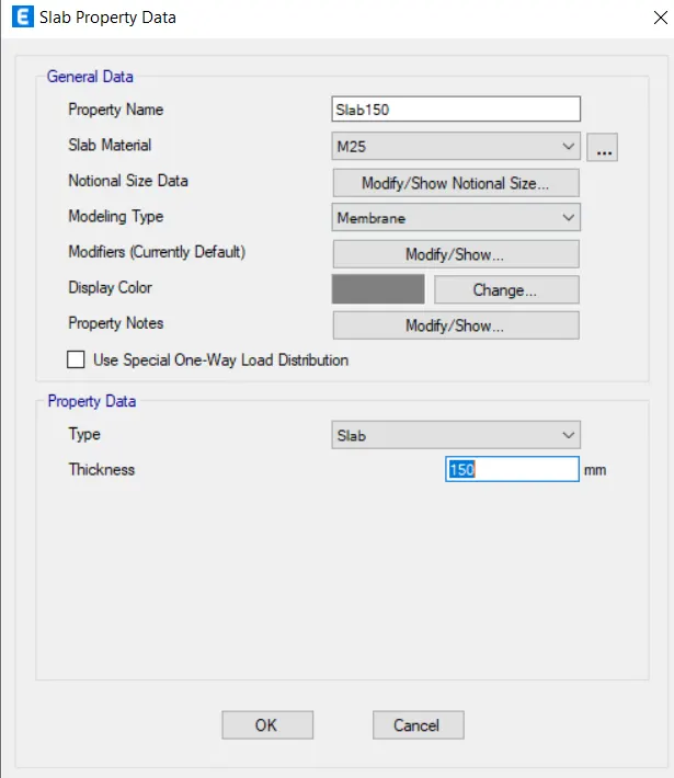
- Rename it as slab150, modelling type as membrane and change thickness as 150mm
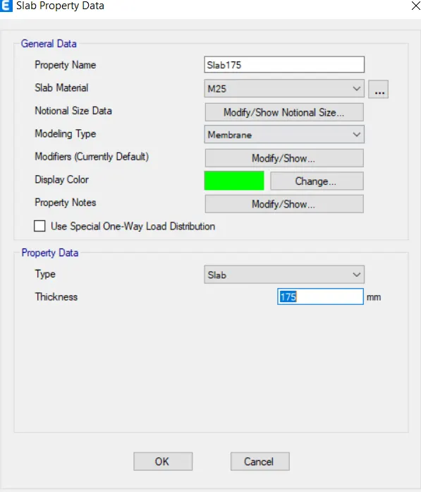
- Similarly define slab 175
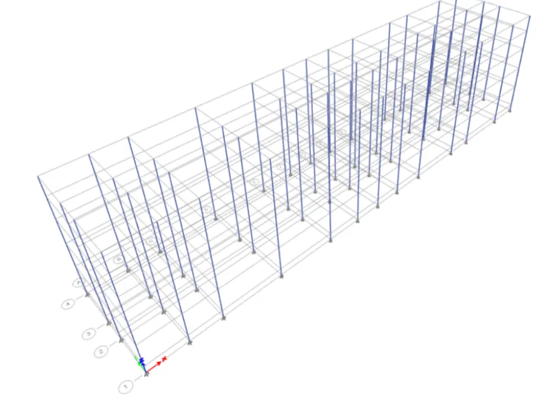
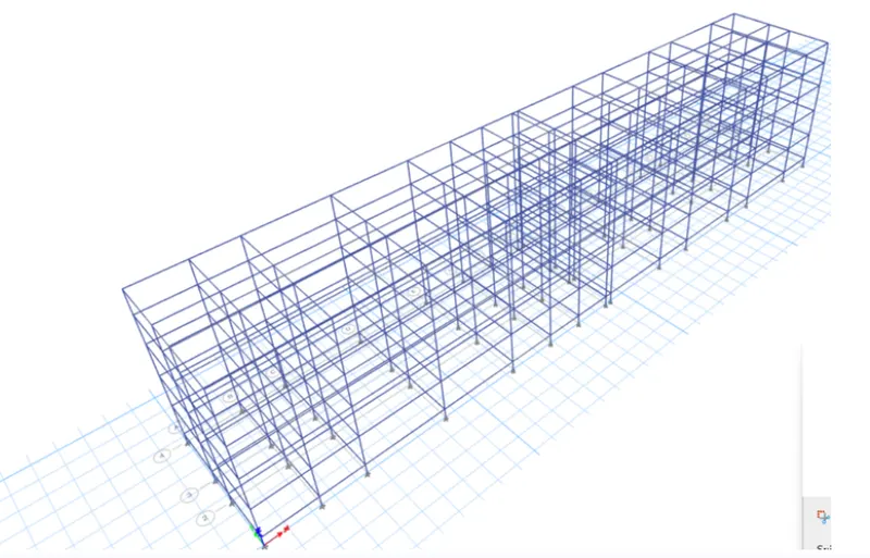
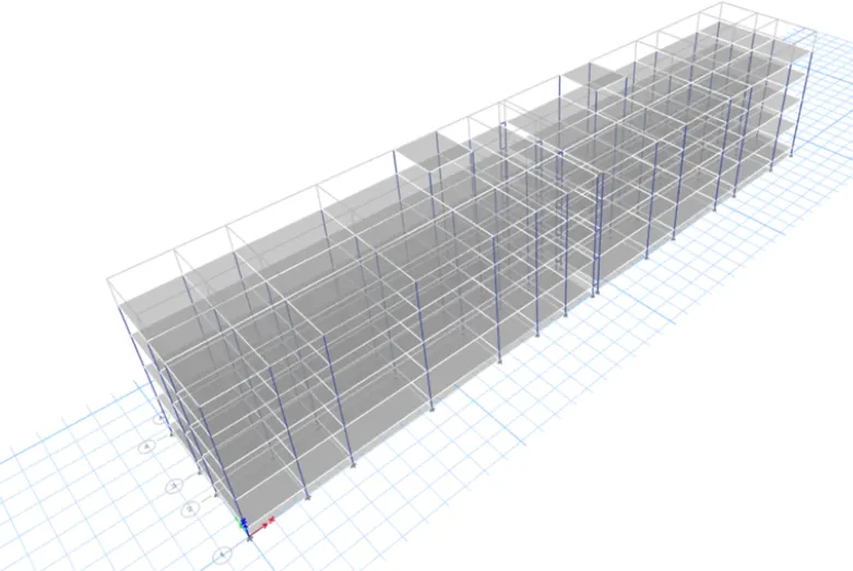
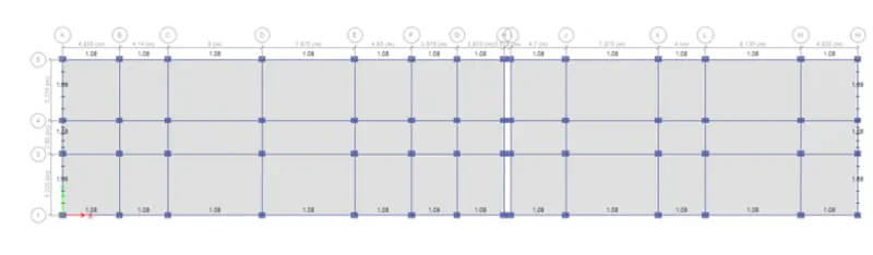
- After adding the section properties now we will be drawing slab, columns and beams in the given plan by using quick draw tool which is provided in the software
COLUMNS:
BEAMS:
SLAB:
STEP:6
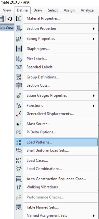
LOAD PATTERNS
- Click on the define and from that select the load patterns
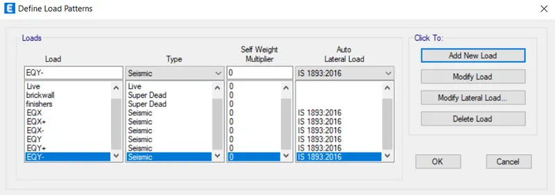
- Define the loads like dead load , live load , brick wall load and earthquake load in x direction and eccentric earthquake loads in positive x and negative x and same loads in y direction also mension IS codes of respective loads
Now we will be assigning the load patterns
STEP:7
LIVE LOADS
- Select the floor and live loads to the structure
- Here we will be providing 2KN/sq.m as a live loads for the rooms and the dormitories of the hostel building according to the IS 875 part 2 for the residential building
- AS per IS code for the hostel building
- living rooms,bedrooms and dormitories:2kN/sq.m
- Kitchen and laundaries :3KN/sq.m
- Public launches:3KN/sq.m
- store rooms:5KN/sq.m
- Dining rooms,cafeteria and restaurant4KN/sq.m
- office rooms :2.5KN/sq.m
- bath and toilets :2KN/sq.m
- Corridors,passages and staiecase :3KN/sq.m
- Balconies:4KN/m
- After applying dead loads to the structure now we will be applying live load
- For that go to assign -->shell loads-->uniform
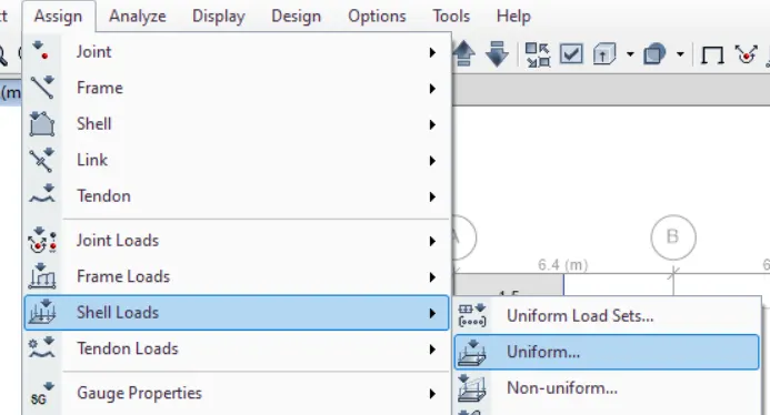
- A new dialouge box will appear and fill it with relevant data
- As we know that according to the is code 875 there is a provision which says that in residential buildings that the live load for rooms must be 2KN/sq.m
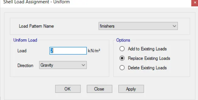
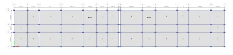
- And for the corridor it should be3 kN/sq.m
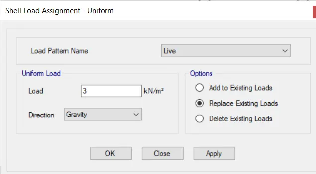
- Live load for terrace
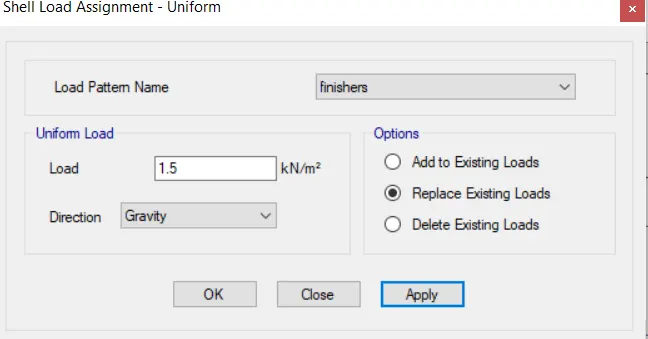
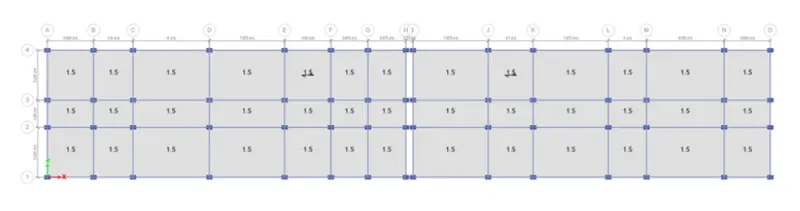
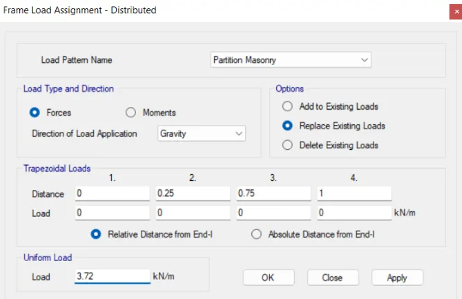
AAC BLOCK LOADS
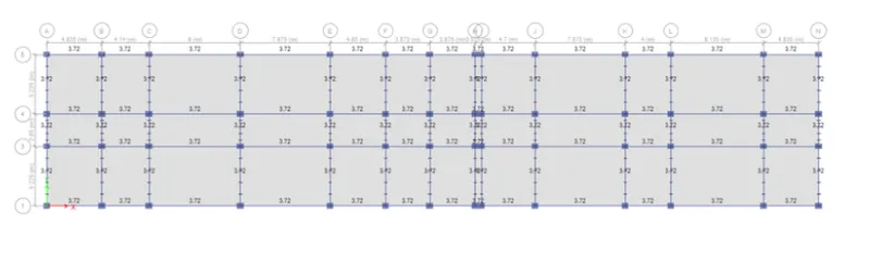
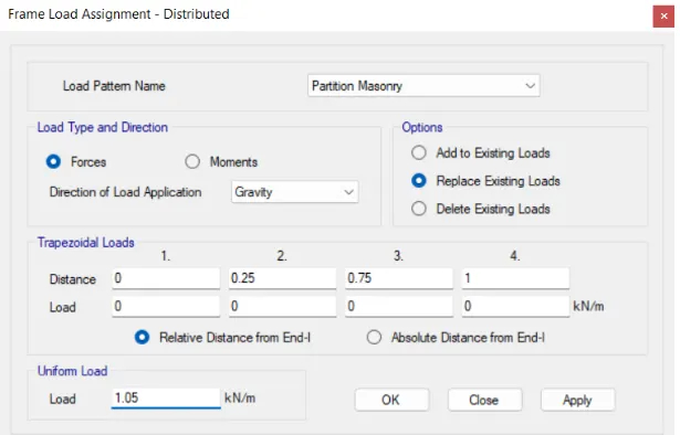
AAC LOAD FOR TERRACE
STEP:8
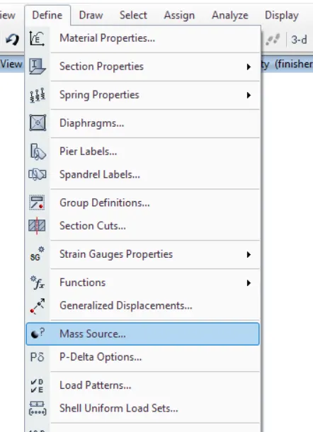
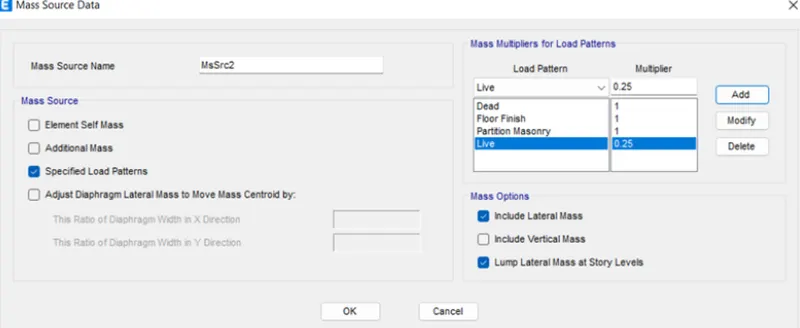
- Now we have to assign the mass source for this structure
- Another dialouge box appears and fill it with appropriate data
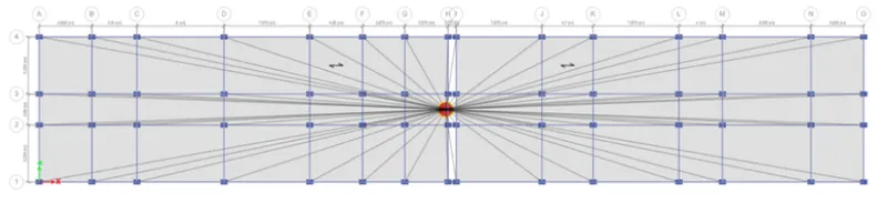
- After assigning mass source now we have to assign the diaphragm
- For that first we need to select
- then go to assign--shell-->diaphragm
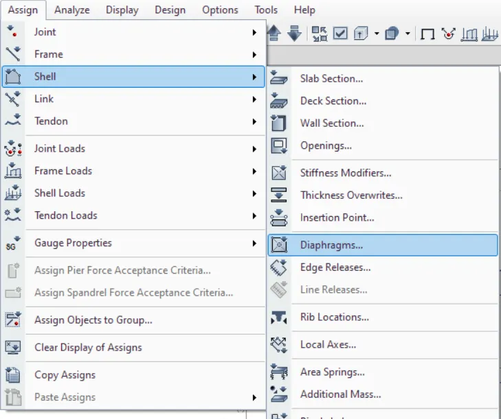
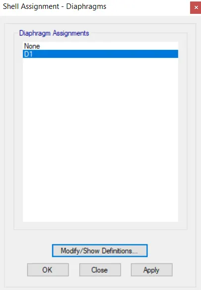
- There will be another dialouge box select D1 and click on the apply and then click ok
Modal Analysis
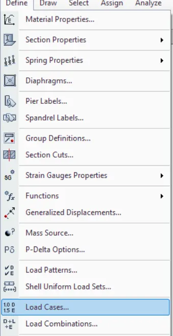
- Go to define -->load cases
- New dialouge box will appear in that select add new case
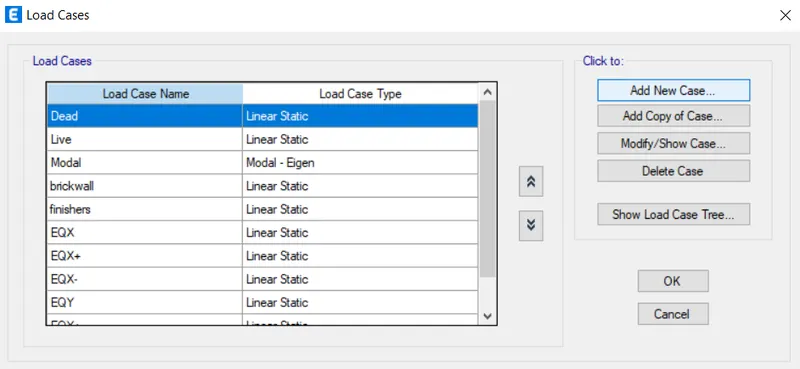
- Another dailouge box will appear enter the relevant data required
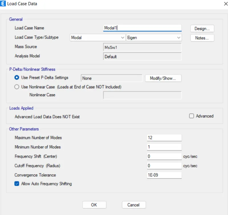
- After this we will be assigning spectrum analysis
- For that go to define --> functions-->spectrum analysis
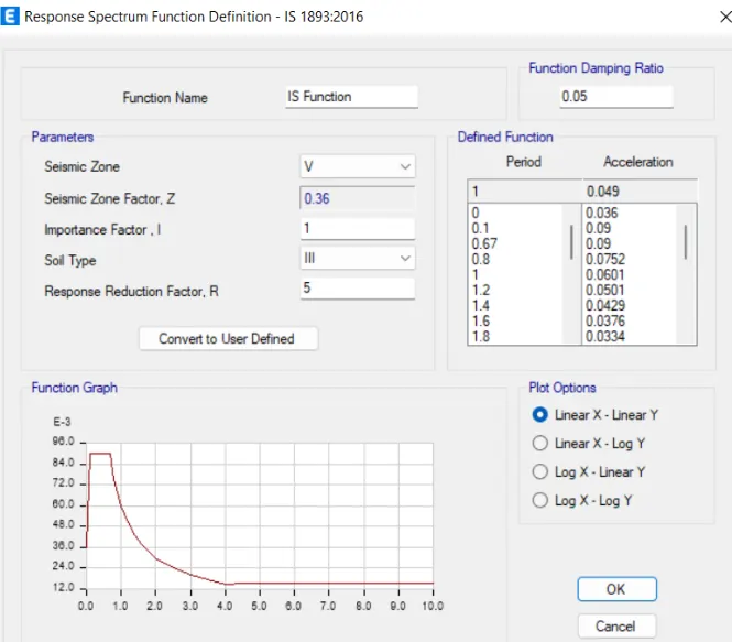
- A new dialouge box will appear in that choose ia 1893-2016 and click on th add new function
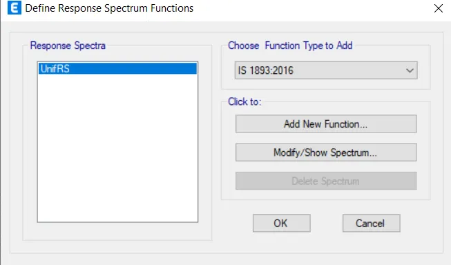
- After clicking that new dialouge box will appear fill it with relevant data
The response spectrum load case in X direction :RX
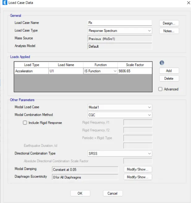
The response spectrum load case in Y direction :RY
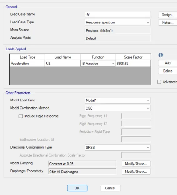
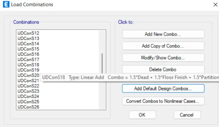
- we have to assign the load combinations
- For that go to define ---> load combination
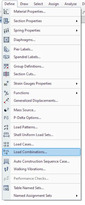
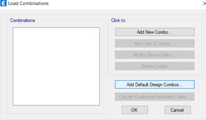
- There will be another dialouge box in that click on the option add default combos
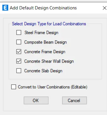
- Another dialouge box appears in that click on the option concrete frame design and concrete shear wall design , then click on the option ok
- Another dialouge will appear in that all ETABS generation load combination will be there
STEP:9
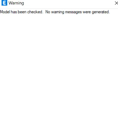
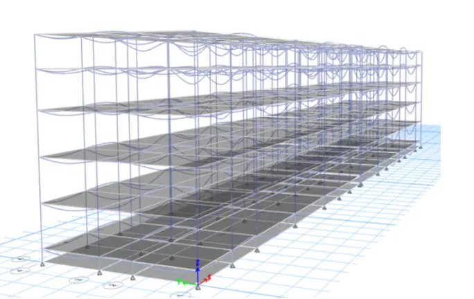
Check the model and run analysis
STEP:10
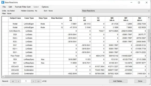
- After we enter these for response spectrum as scale factor at x and Ydirections in load case data,then the EQ is closer to the RS from the base reaction table
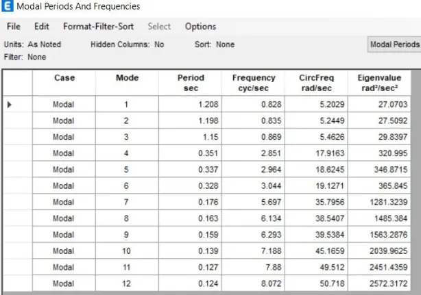
- Principal modes to be greater than torsional mode
- modal 1 and 2 is greater than modal 3, hence achieved
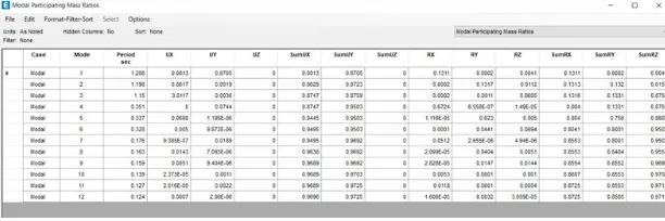
- Modal mass ratio in x-direction 0.013+0.86=0.813
- Hence 65%is achieved in x-direction
MAXIMUM STOREY DRIFT RATIO EQX AND EQY
- Display -->storey response plots
- In display type-->check max storey drifts
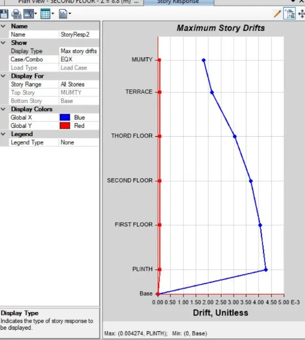
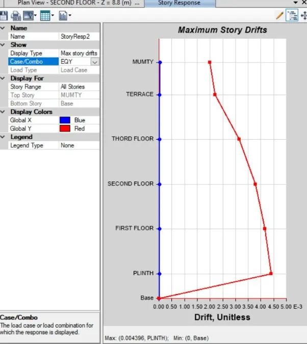
- As we check in EQx, the maximum storey drifts is 0.004
- As we can check in EQy, the maximum storey drifts is 0.004
- Hence inter storey drits ratio is limited within 0.004
SAFE SOFTWARE
STEP:1
- First we neeed to export the filr from the ETABS software
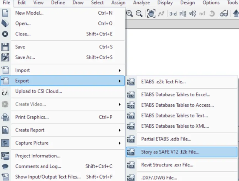
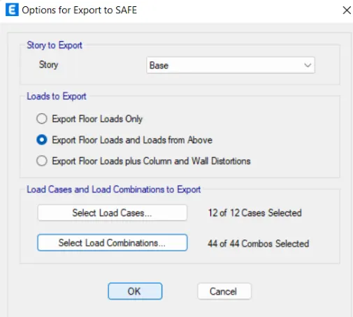
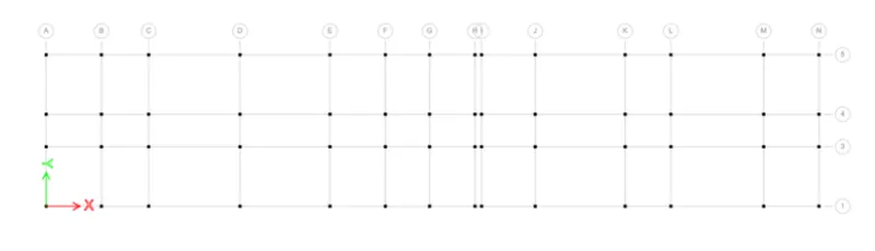
- Now save the file and go to safe sofware and open the file
GIVEN DATA
Column size:450mm*600mm
Soil type :lll
Length of the piles :10m
Pile diameter:500mm diameter
load carriying capacity of pile : 280KN
pile length:16mm
soil bearing capacity :150KN/m
STEP:2
Define materials
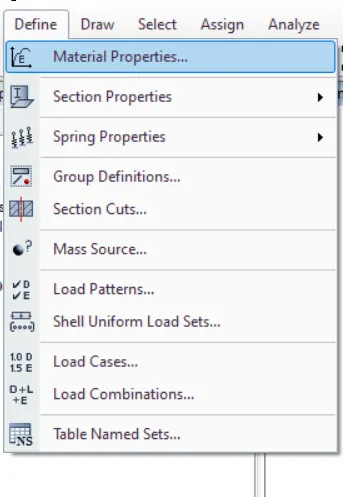
- Add M25 concrete
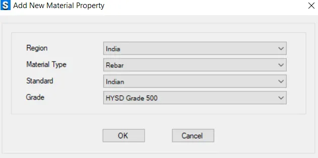
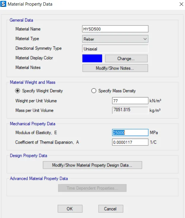
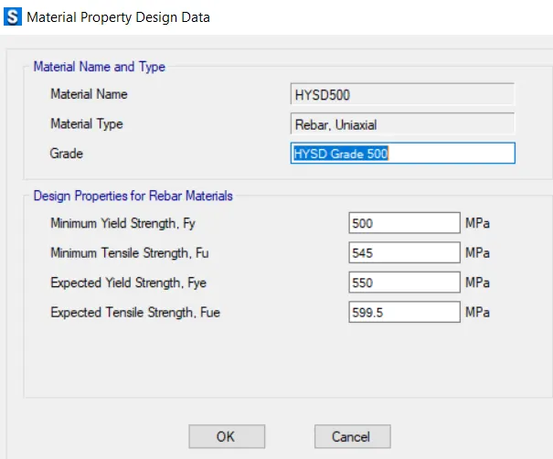
- Add rebar Fe500
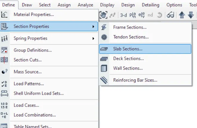
Define slab properties
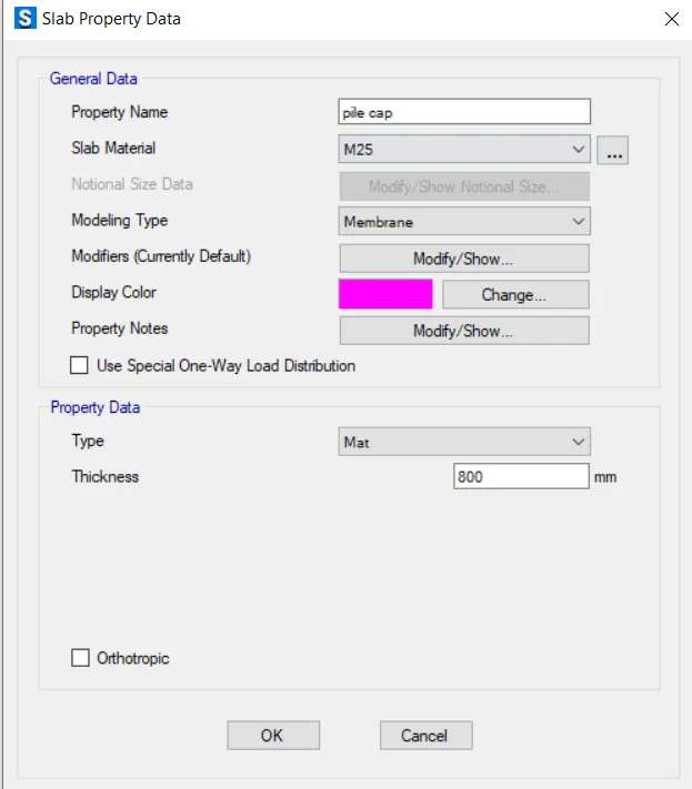
- Define pile cap
- Define pile

COLUMN STIFFNESS
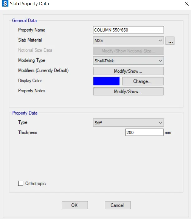
FRAME SECTION FOR TIE BEAM
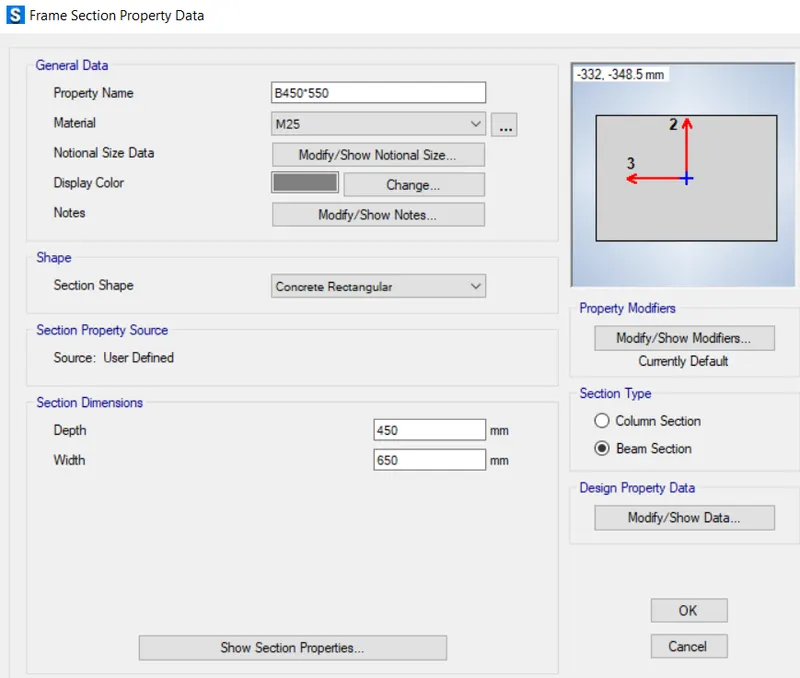
STEP:3
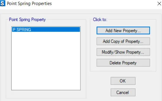
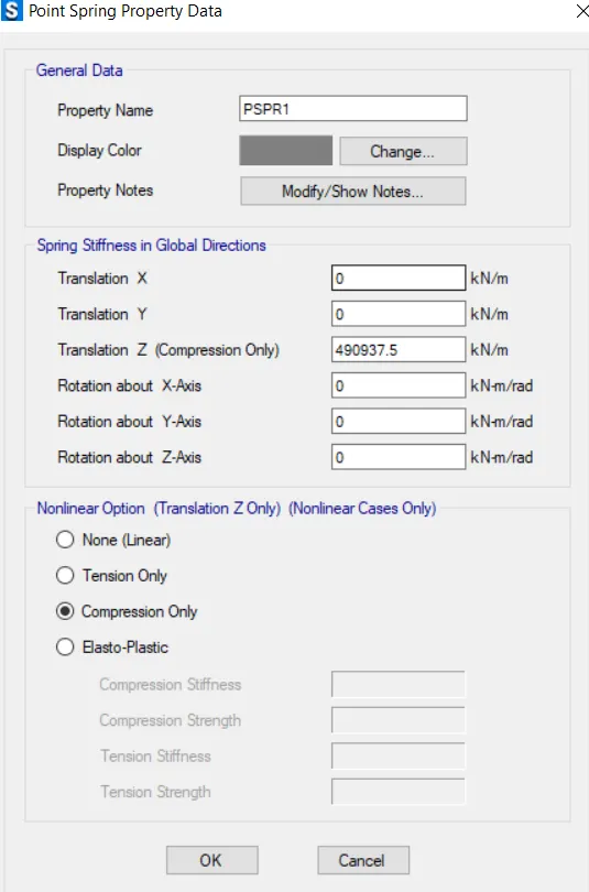
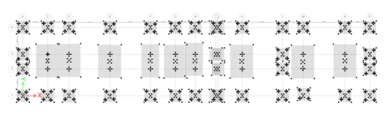
- Springs were added
- Select pile-->assign-->support data-->point springs
- The spring constant is taken as the above calculation
- Add piles at the point
- Modify the edge distance to 0.2m
- create column and draw column in the center using the quick draw tool
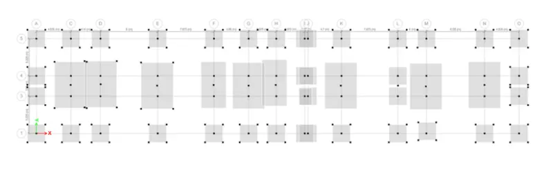
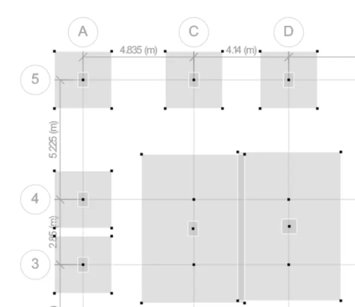
STEP:4
Assign load combinations
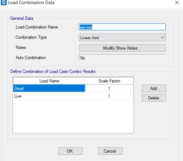
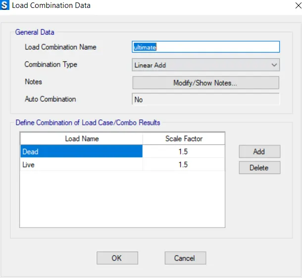
- After definning the load combination,run the analysis
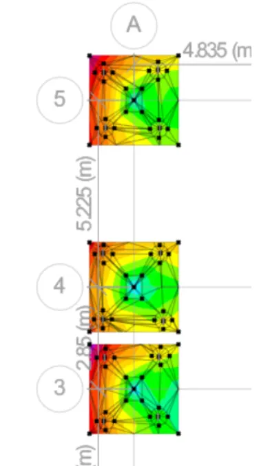
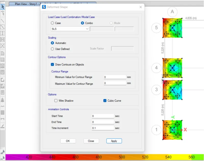
CHECK FOR SETTLEMENT
According to the codebook a total settlement of 25mm is allowable not more than that.So the allowable settlemet in our case is less than the permissible limit.hence ok.
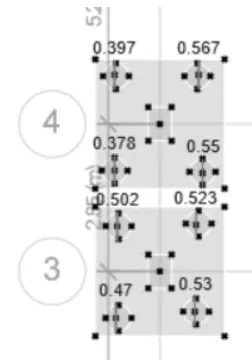
CHECK FOR PUNCHING SHEAR
According to the IS code the punching value should not cross th unit value,should not cross the unit value,so in our case, the punching shear value is less then the unit value .hence ok
reinforcement slab design
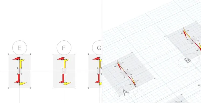
The hostel building has been designed and analyzed by the SAFE sofware successfully