Project 2_Design & Analysis of a Hostel building at Guwahati, Assam
AIM:
1. To calculate and assume data from the given Architectural and site information
2. To model, Analysis and design the frame structure using Etabs Software
3. To model, Analysis and design the foundation using safe software
4. To produce a structural typical floor plan& typical Rebar Drawing
PROCEDURE:
- Open the Etabs software and click on the new model
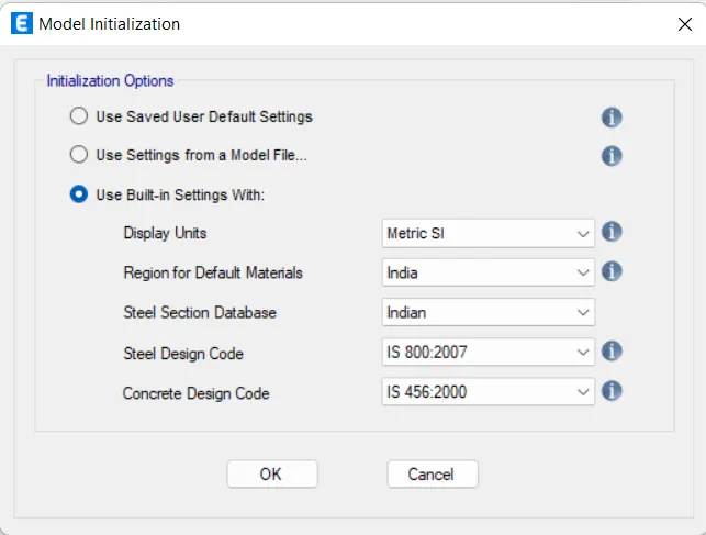
- Now determine all the aspects for model Initialization
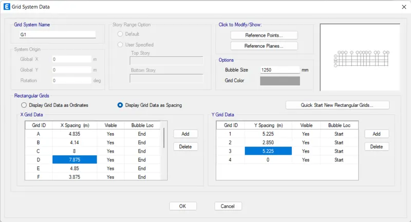
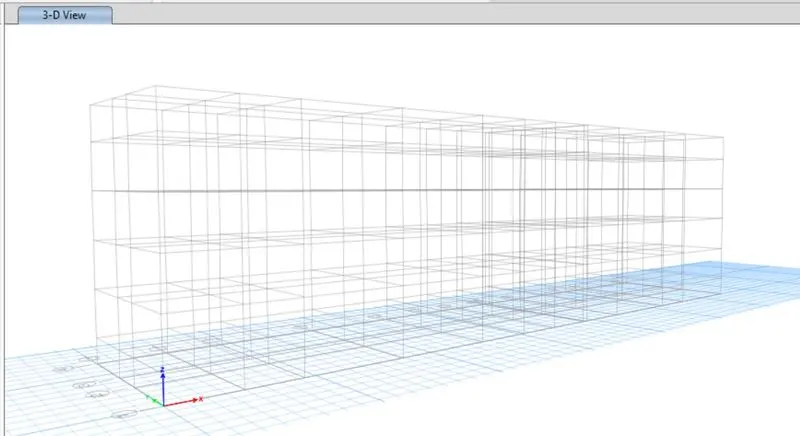
- Now determine the grids required for the model
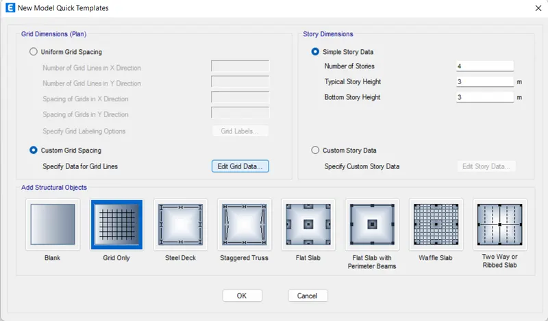
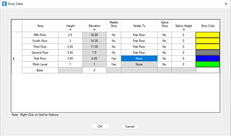
- Now determine the number of stories required
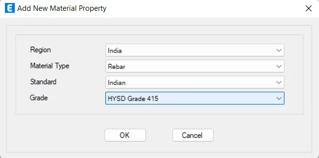
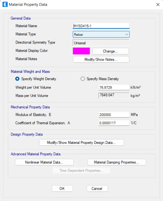
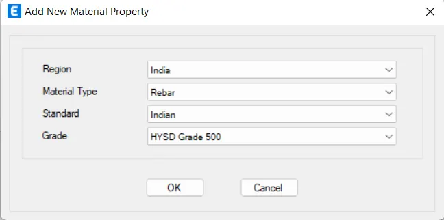
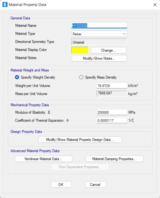
- Now its time to determine the material
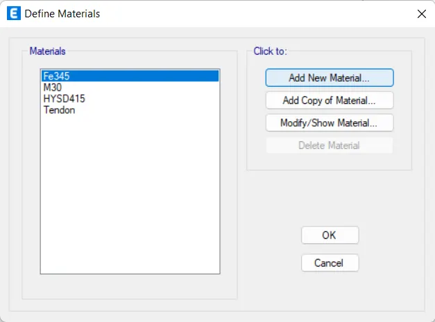
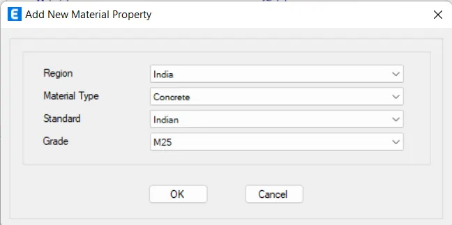
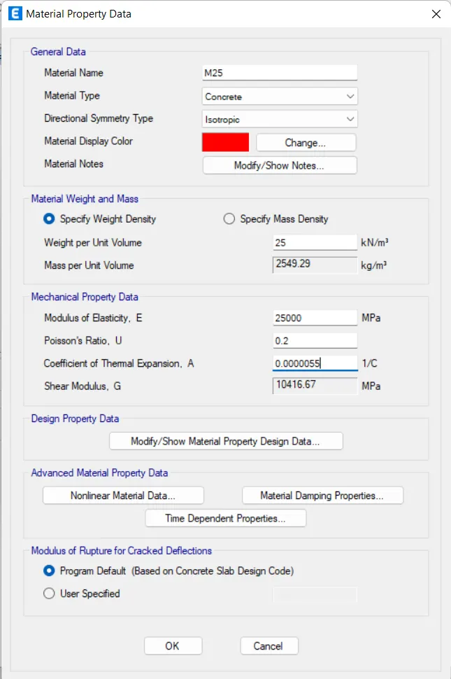
M25 Concrete
FE415 Rebar
Fe500 Rebar
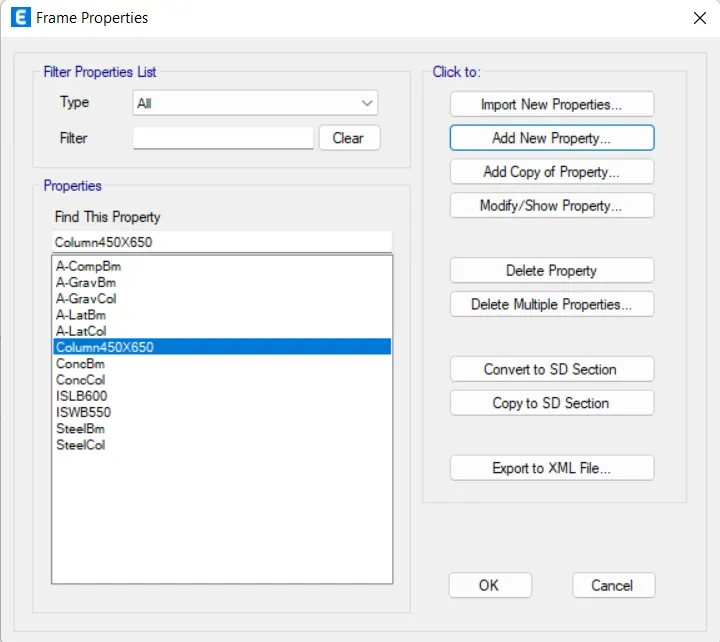
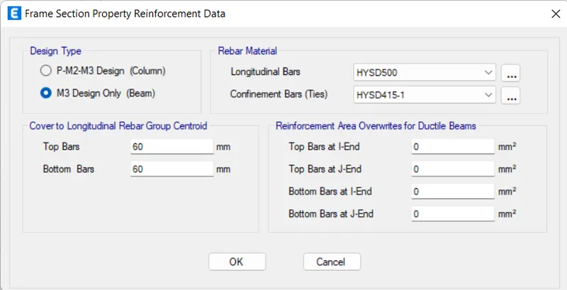
- Now it is time to determine Column& beam
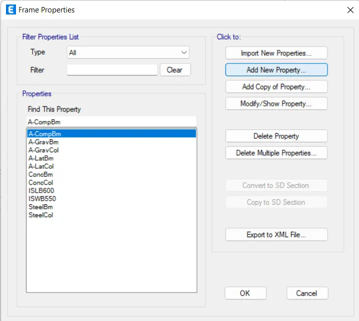
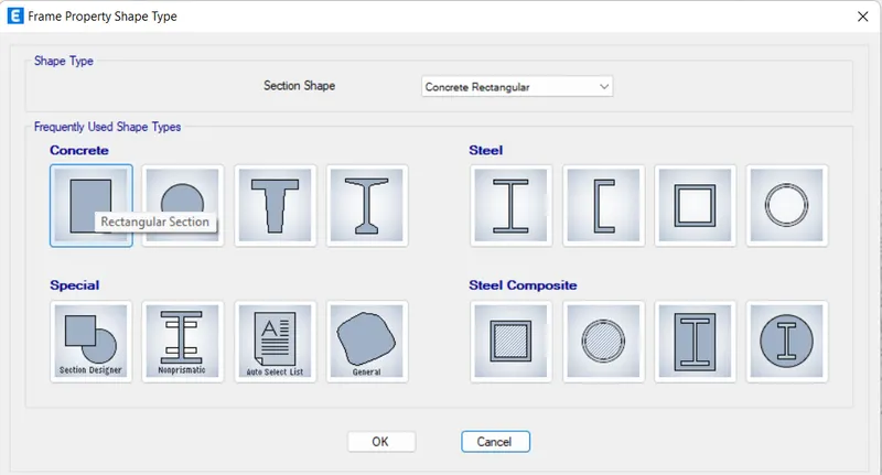
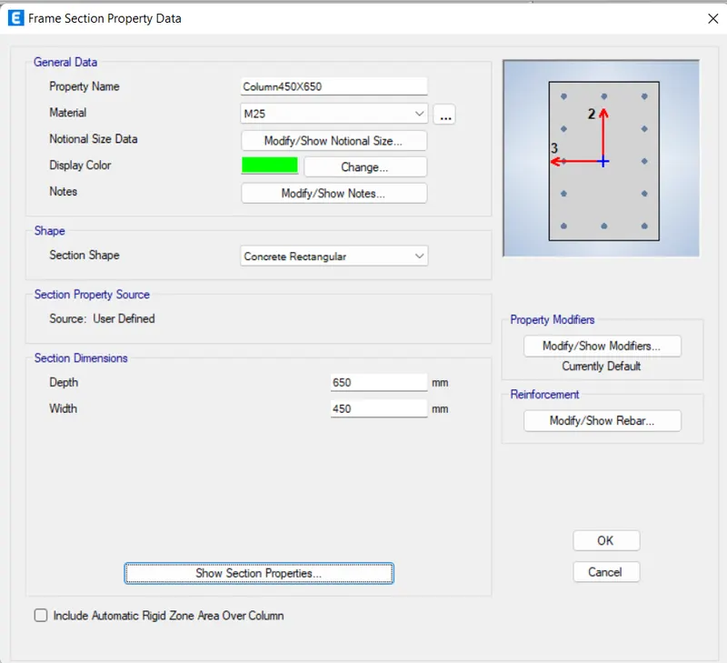
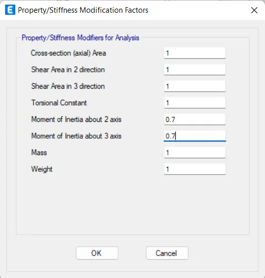
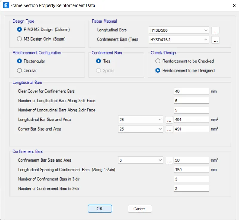
- Column 450x650mm
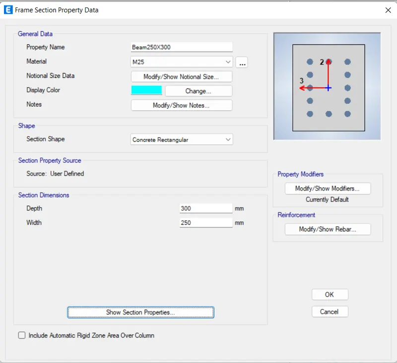
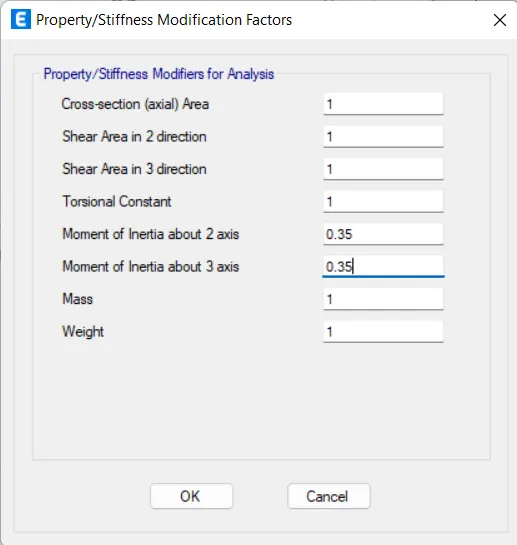
-Beam 250x3000mm
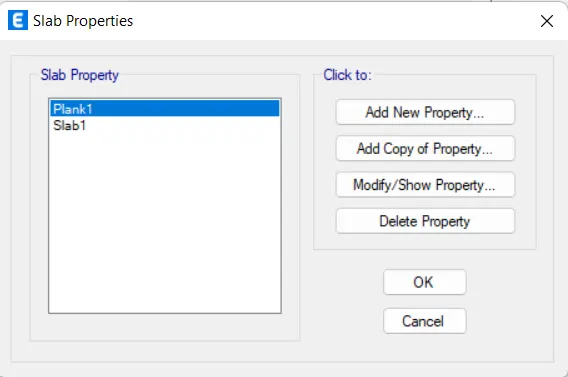
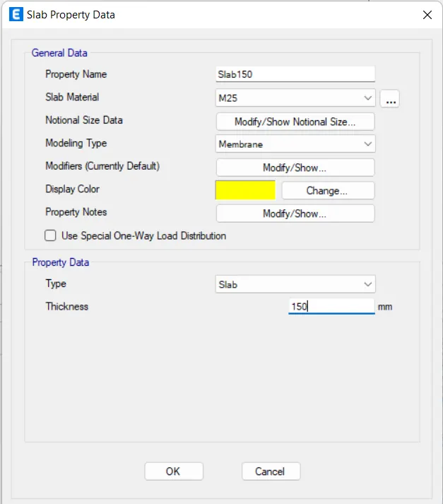
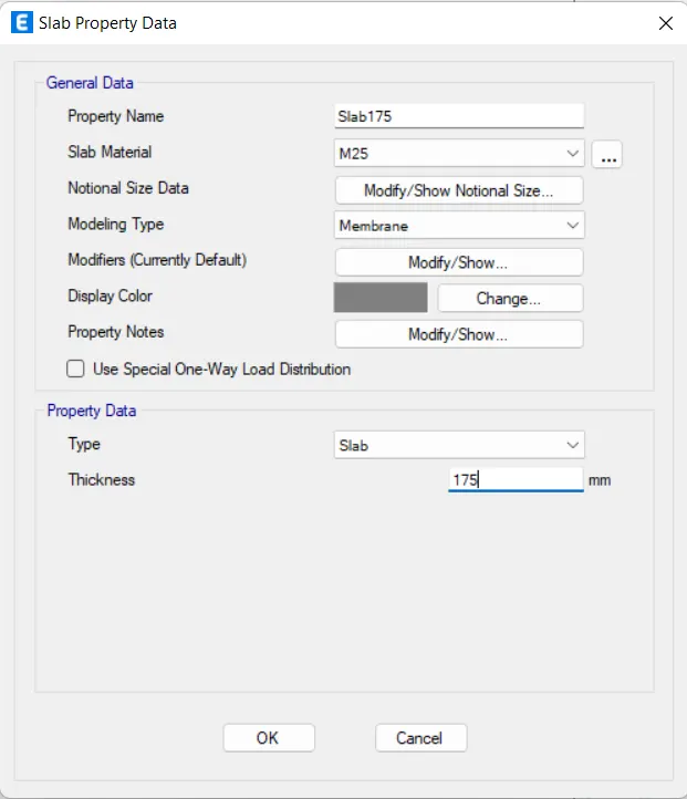
- After this there will be another dialouge box named as Slab Property Data,fill the relevant data in the given dialouge box
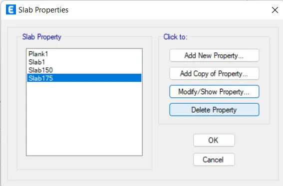
- And for the staircase we will be providing slab of 175mm thickness,and to add the slab for the staircase we will have to add the new property and then fill out the all relevant data in the new slab property dialouge box just as shown in the below given image:
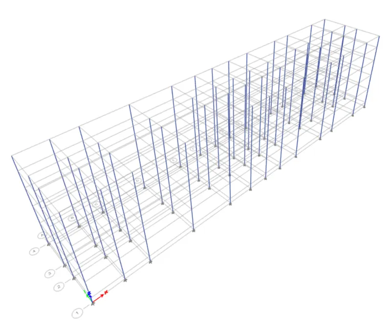
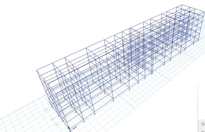
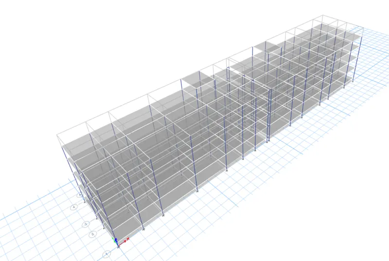
- After adding the section properties now we will be drawing slab,columns and the beams in the given plan by using quick draw tool which is provided in the software.
- COLUMNS:
- BEAMS:
- SLAB:
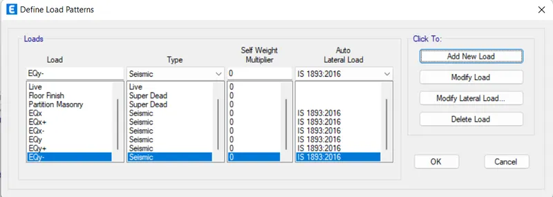
- Load Patterns:
- And now we will be assigning the load patterns:
- Below are the given images of assigned loads:
- LIVE LOADS:
-
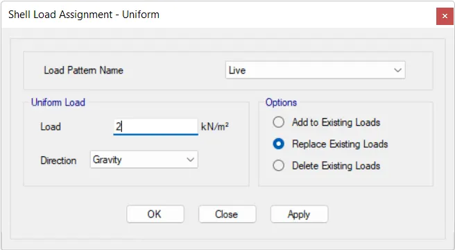
Now seelect the floors and add the Live loads to the structure.
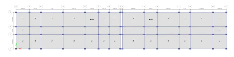
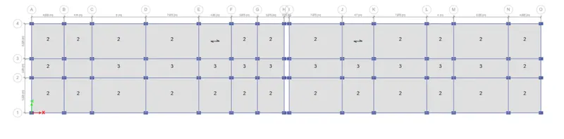
- Here we will be providing 2 KN/sq.m as a live load for the rooms and the dormitories of the hostel building according to the IS 875 part 2 for the residential buiding.
- As per the IS code for the hostel building:
- Living Rooms,Bedrooms and the Dormitories : 2 KnN/sq.m.
- Kitchen and Laundaries : 3 KN/sq.m.
- Public Lounges : 3 KN/sq.m.
- Store Rooms : 5 KN/sq.m.
- Dining Rooms,Cafeteria and Restaurants : 4 KN/sq.m.
- Office Rooms : 2.5 KN/sq.m.
- Bath and toilets : 2 KN/sq.m.
- Corridors, Passages and Staircase : 3 KN/sq.m.
- Balconies : 4 KN/sq.m.
- LIVE LOAD FOR CORRIDOR:
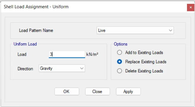
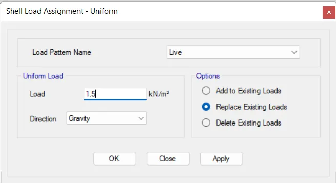
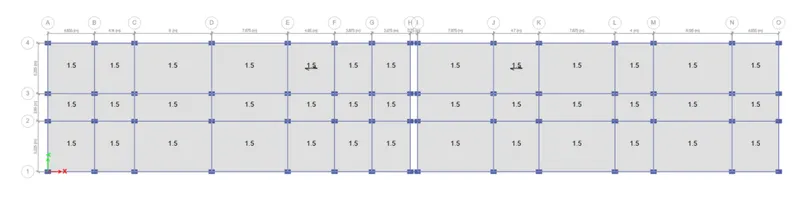
- LIVE LOAD FOR TERRACE:
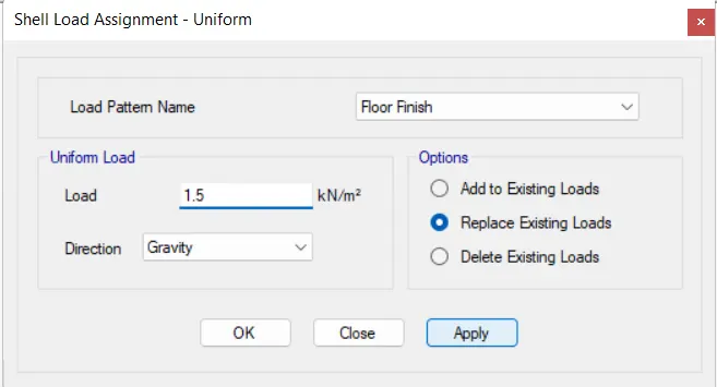
- FLOOR FINISH:
- AAC BLOCK LOADS:
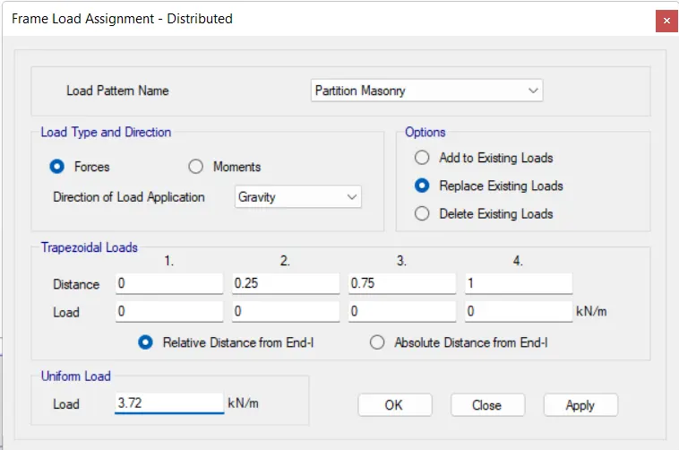
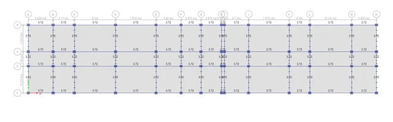
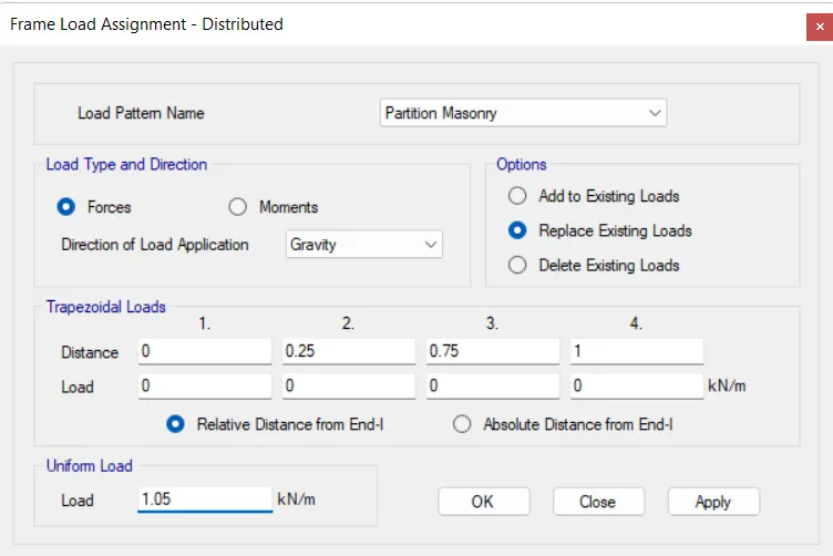
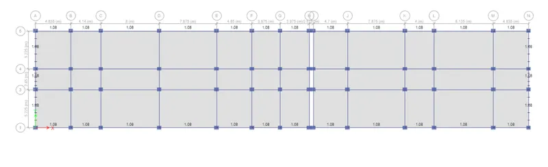
- AAC LOAD FOR TERRACE:
- Now we will be assigning the loads now we will be definning the Mass source,Mass Modal and the Response Sprectrum Function:
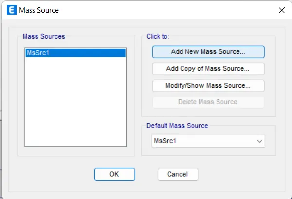
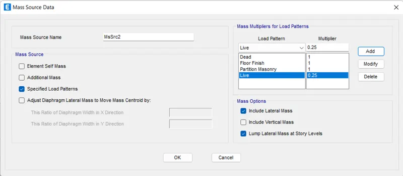
- Then there will be another dialouge box named as Load Cases in that dialolouge box there will be an option called Add New Cases
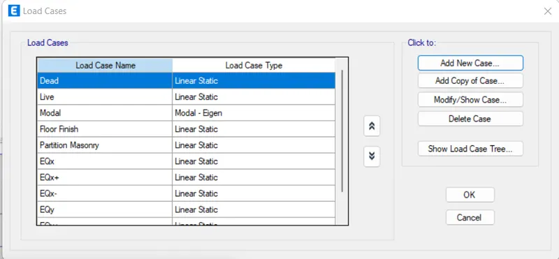
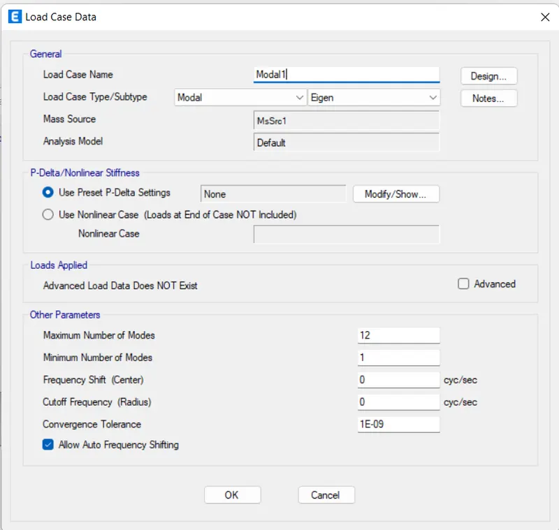
- Determine Diaphram for the structure
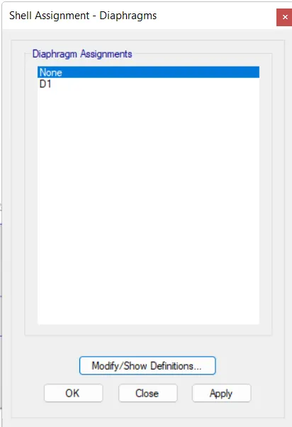
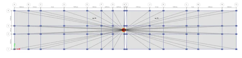
- determining Response Spectrum Function
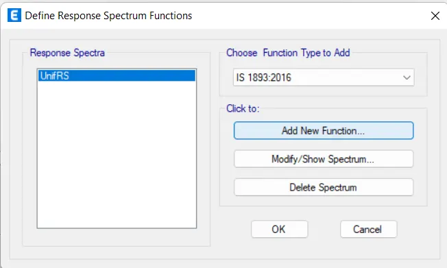
RESPONSE SPECTRUM FUNCTION:
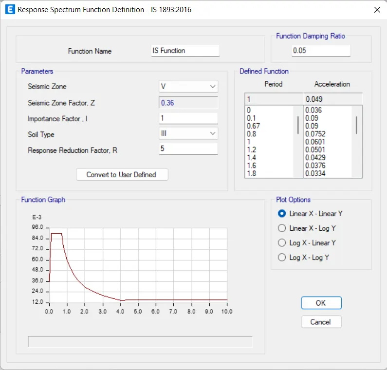
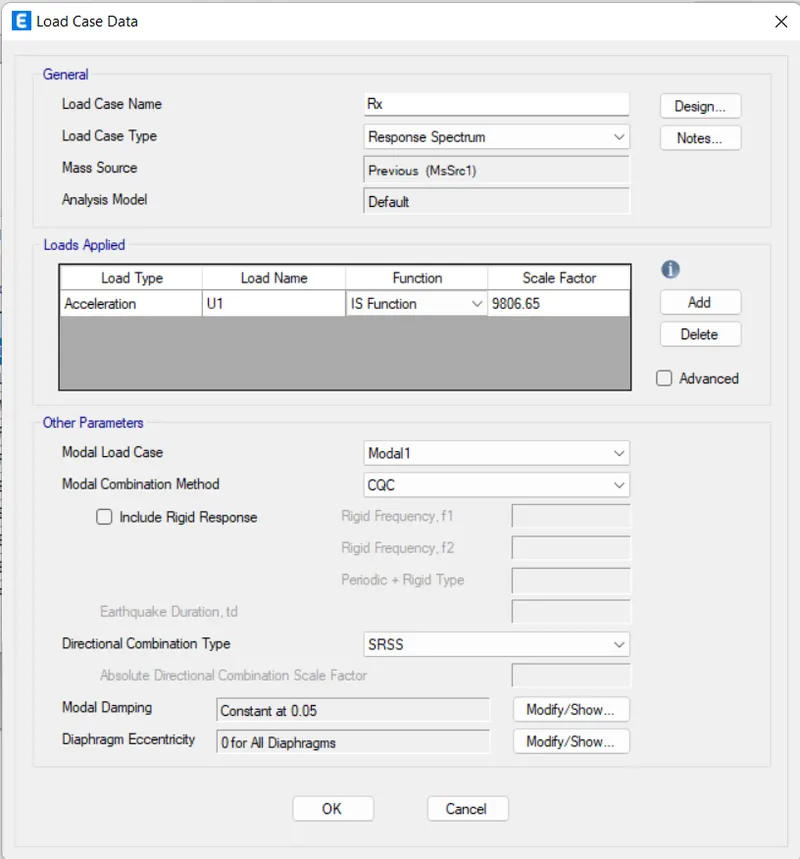
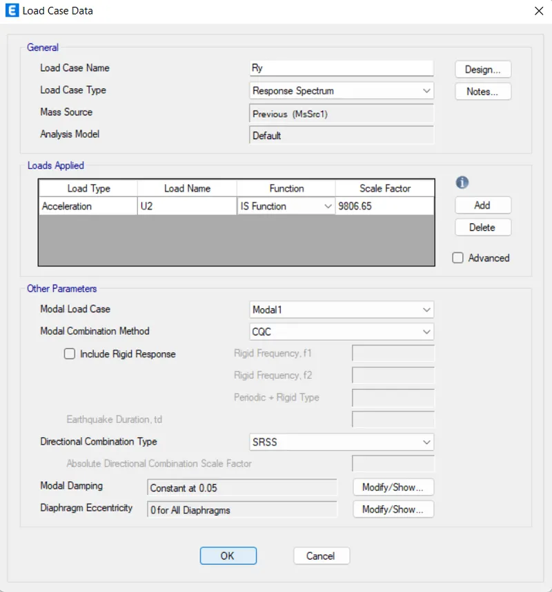
- Then there will be another dialogue box named the Load Case Data, in that dialogue box fill the data just as shown in the below-given image:
Rx:
Ry:
 .
.
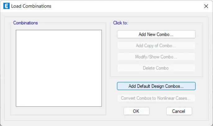
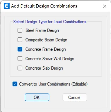
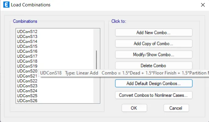
- And then there will be a new dialouge box named as Load Combinations in that dialouge box there will be an option called Add Default Design Combo just click on that option
LOAD COMBINATIONS:
CHECKING THE MODEL:

RUN ANALYSIS:
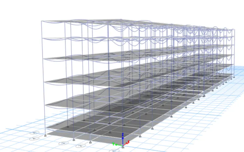
- And now we will be doing the Structural Output Check:
Modal Response for G+3 Hostel Building. We get.
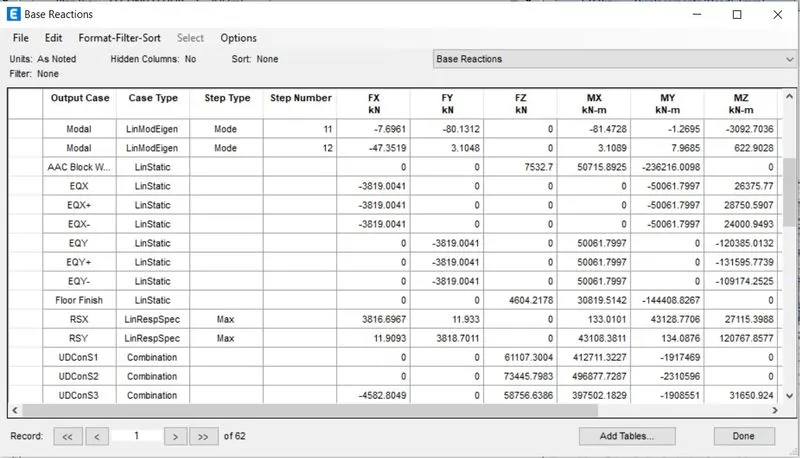
- After we enter these for response spectrum as scale factors at x & y-directions in load case data, then the EQ is closer to the RS from the base reaction table, as shown below.
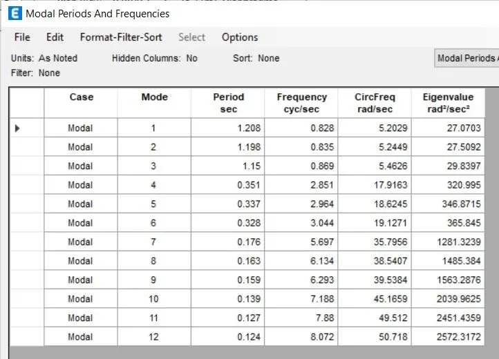
- The shown Principal modes to be greater than torsional mode
- Therefore, modal 1 & 2 is greater than modal 3, Hence Achieved.
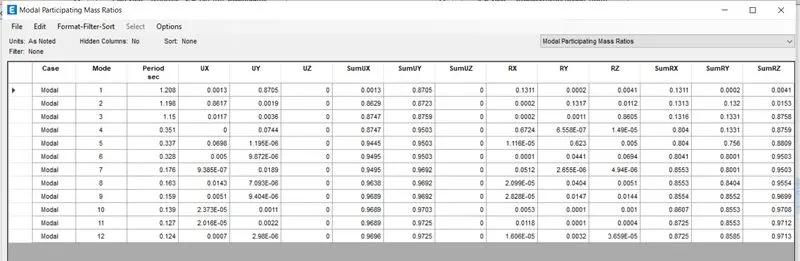
- Modal mass ratio in x-direction 0.013 + 0.86 = 0.813.
- Hence 65% is achieved in x-direction.
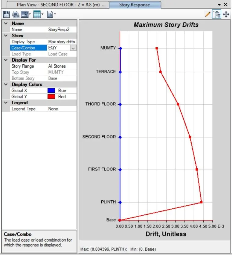
Maximum storey drift ratio EQx & EQy.
- Display > storey response plots.
- In display type > check max storey drifts
- In case/combo> check EQx & EQy, as shown below.
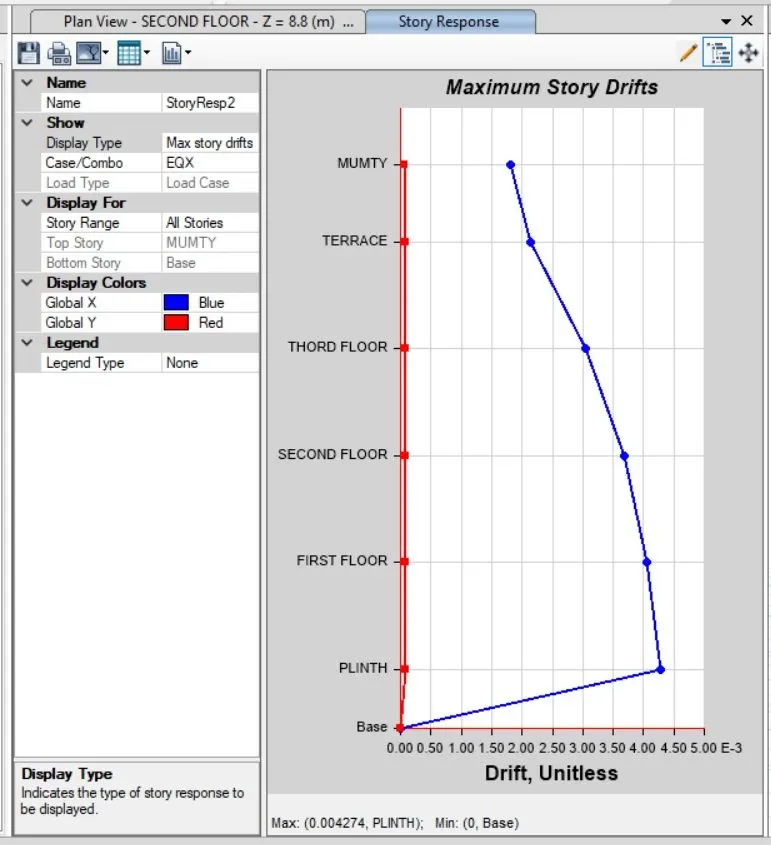
- As we can check in EQx, maximum storey drifts is 0.004.
- As we can check in EQy, maximum storey drifts is 0.004.
- Hence inter storey drifts ratio is limited wthin 0.004.
Concrete Frame Design:
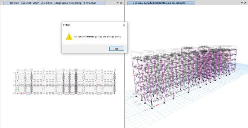
BEAM DESIGN:
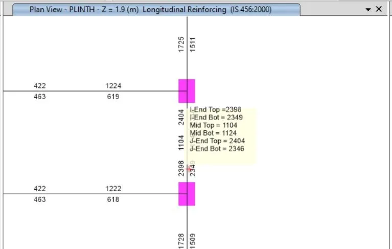
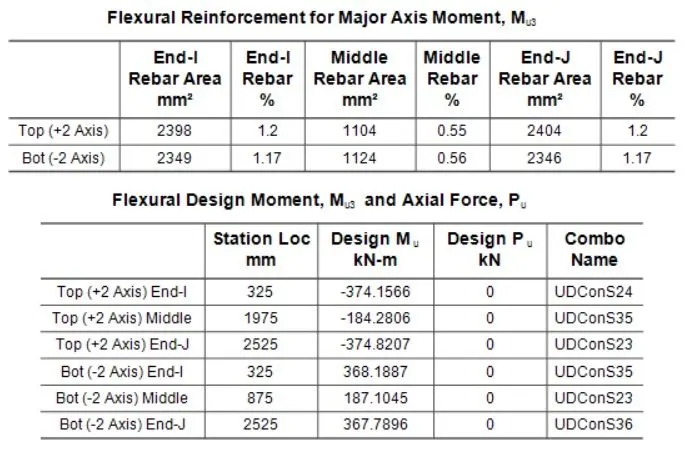
Longitudinal Reinforcement of Beam at Grid-N.
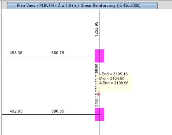
Shear Reinforcement of Beam at Grid-N.
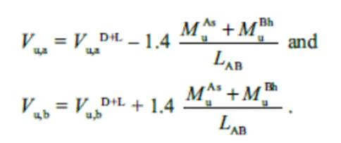
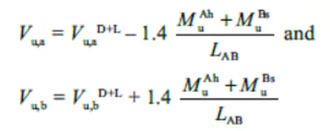
1). For Sway Shear Force Right 2). For Sway Shear Force Left
Design moment values from Etabs.
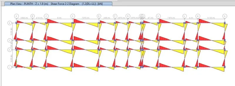
Shear Force values for selected beam from Etabs,
As per IS 13920 1.2 loading applied for (DL+LL).
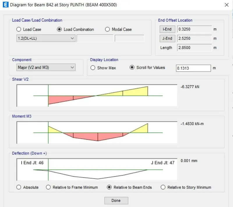
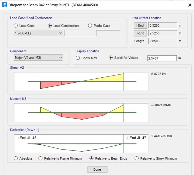
SF value at point A SF value at point B
As per IS 13920-2016 clause 6.3.3 (b)
Mas = 368.18 KN-m Mah = 374.15 KN-m
Mbh =374.82 KN-m Mbs =367.78 KN-m
L ab = 2.20 m Lab = 2.20 m
Vu,a(d+l) = 6.32 Vu,b(d+l) =6.87
Vu,a = 331.4 KN Vu,a = 465.81 KN
Vu,b = 344.6 KN Vu,b = 479 KN
Grid N_At TOP
- Maximum Ast at support = 2398
- Maximum Ast at middle = 1104
- 3 # of 25 mm = 1473
- 3 # of 20 mm = 942
-
Therefore, to satisfy the support we need to provide 3# of 25 mm bar and additionally in the middle need to provide 3# of 20 mm.
Grid N_At BOTTOM
- Maximum Ast at support = 2349
- Maximum Ast at middle = 1124
- 3# of 25 mm = 1473
- 3 # of 20 mm = 942
-
Therefore, to satisfy the support we need to provide 3# of 25 mm bar and additionally in the middle need to provide 3# of 20 mm.
- As per clause 6.3.3 the design force of equivalent Ve = 507.9 KN.
- The shear force under the linear analysis as per the load combination of UD cons23 = 351.07 KN.
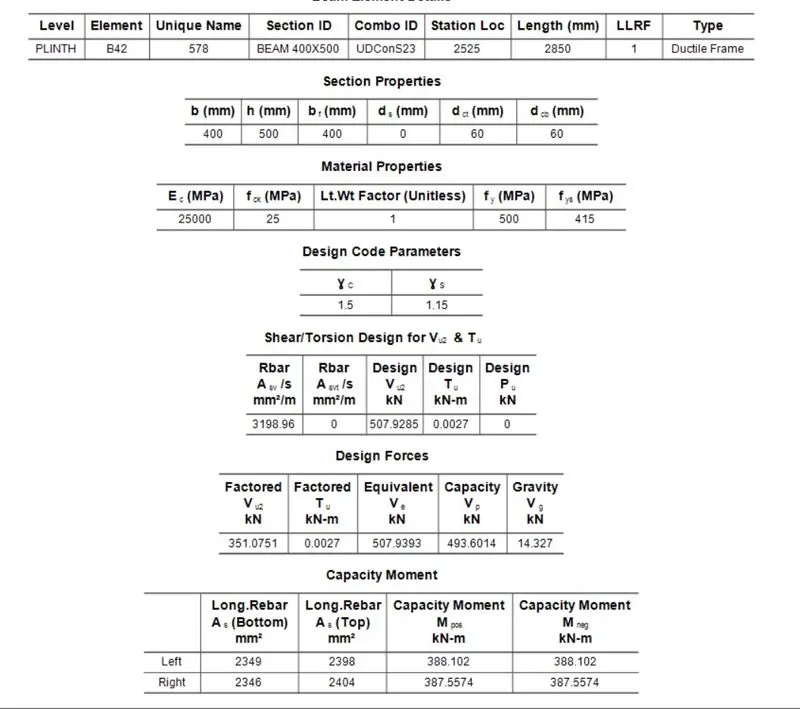
Shear capacity in the beam as per drawing:
(As per IS 456-2002 clause 40.4)
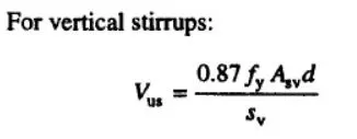
Fy = 415 N/mm2
Asv = 151 mm2
d = 650 mm
Sv = 100 mm
Vus =354.37 KN-m.
COLUMN DESIGN:
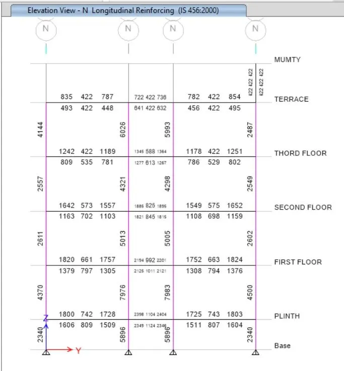
Longitudinal Reinforcement of Column at Grid-3N.
from Etabs (450x650):
Shear Reinforcement of Column at Grid-3N.
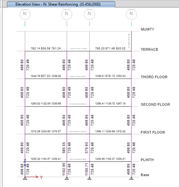
GRID 3N:
The calculation for Longitudinal Reinforcement:
- From the base to the first floor, the maximum Ast is = 7983 mm²
= 7983 / 10 = 793 mm²
= Considering 32 mm dia = Ast = 804 mm²
- So, we can provide 10# of 32 mm dia Longitudinal bar= 10 x 804 = 8040 mm²
The calculation for Shear Reinforcement:
- From the base to the first floor, the maximum shear value is = 720 mm²
=(1000/Sv) X L x Ast
= 1000/200 x 2 x 78.55
=785.5 mm²
- So, we can provide 10mm dia @200 mm spacing shear.
- Therefore, it can be satisfied the entire span.
SAFE SOFTWARE:
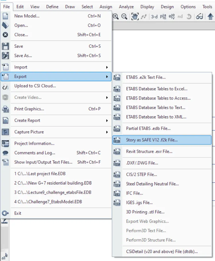
- First, we need to export the file from the ETABS software.
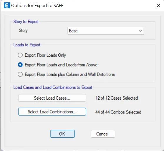
- Now save the file according to our preferences and now go to the SAFE software and now open the file.
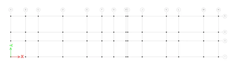
- And now first of all let's extract the given data that is already given in the question itself.
GIVEN DATA:
Column Size: 450 mm X 600mm and 600 mm X 450 mm.
Soil Type: III.
Length of the piles: 10m.
Pile Diameter: 500 mm diameter.
Load Carrying Capacity of Pile: 280 KN.
Pile Cap - Slab type _ Matt of 50 mm thickness.
Column Cap - Slap type - Stiff of 500 mm thickness.
Pile length: 16 mm
Soil Bearing Capacity: 150 KN/sq.m.
The first step is to define the materials and the section property.
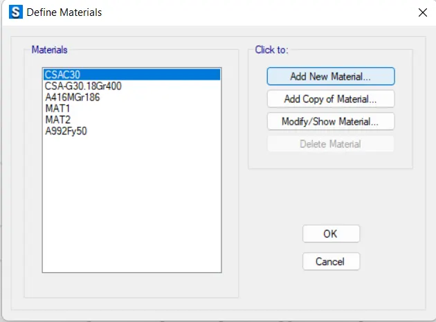
- Now determine the Material property
M30
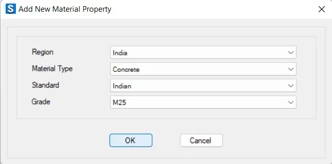
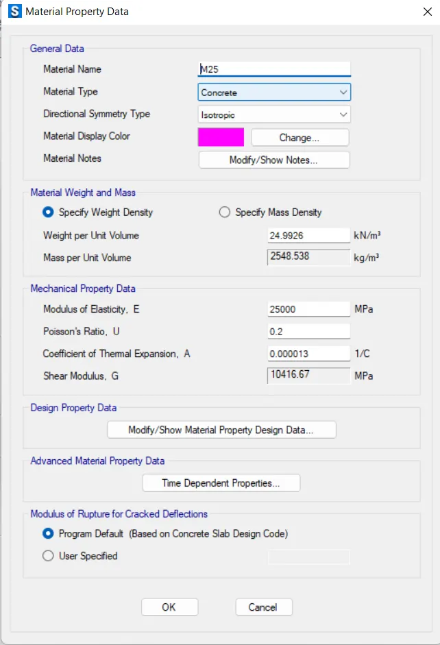
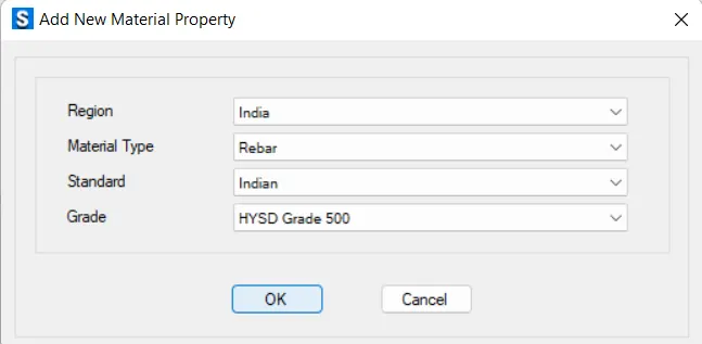
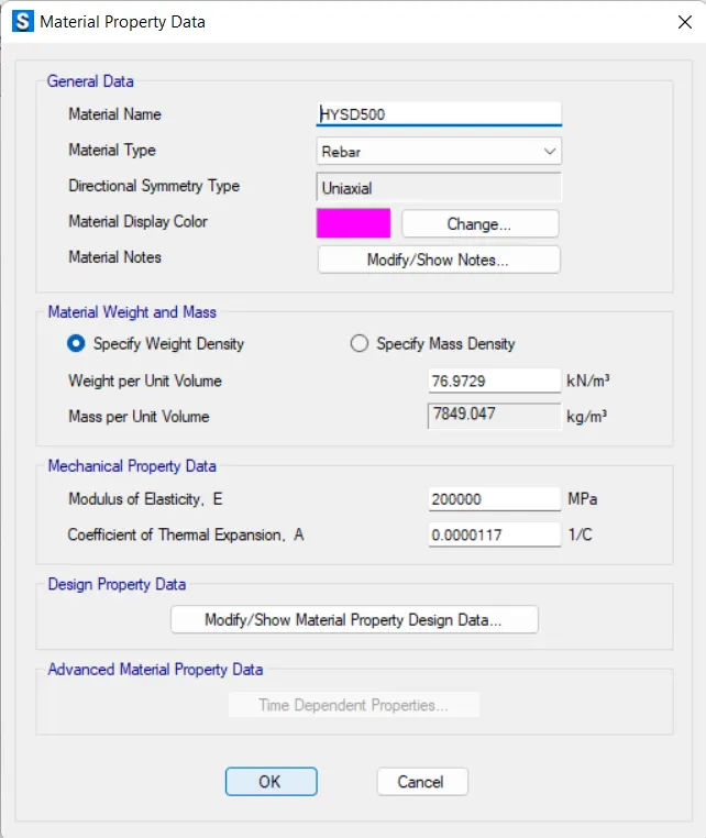
- Rebar Fe 500
- Now determine The slab, pile cap, and Column stiffness
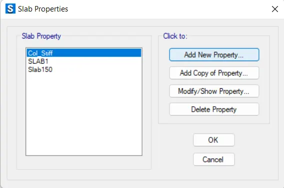
- Pile Cap
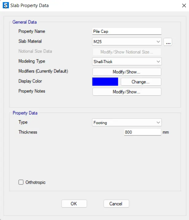
- Piles
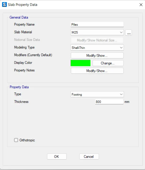
- Column stiffness
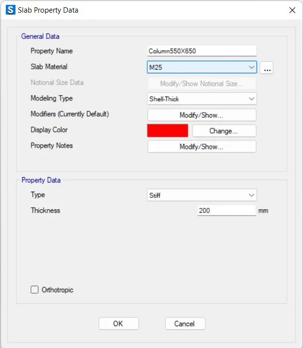
- Frame section for Tie beam
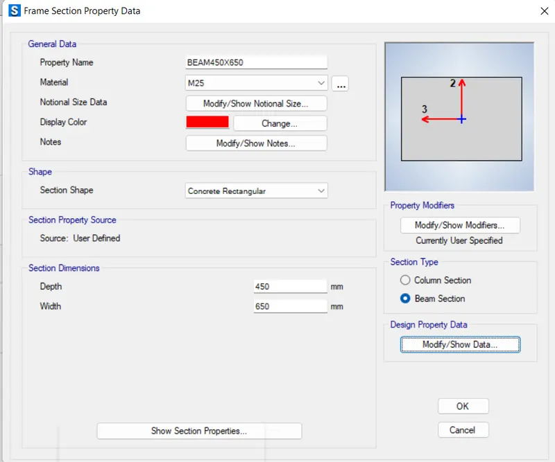
- After that, we have to define the Point Spring property in order to do that just go to the option Define and then there will be a drop-down list and in that list, there is an option called Spring properties to click on that option and after that, there will be another list in that list click on the option Point Spring just click on that option
- Now add a new property
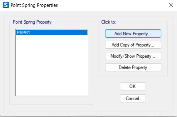
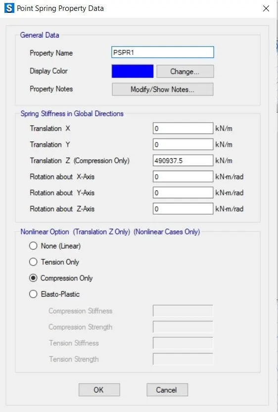
- And then there will be another dialogue box named Point Spring Property Data in that dialogue box fill the data just as shown in the below-given image:
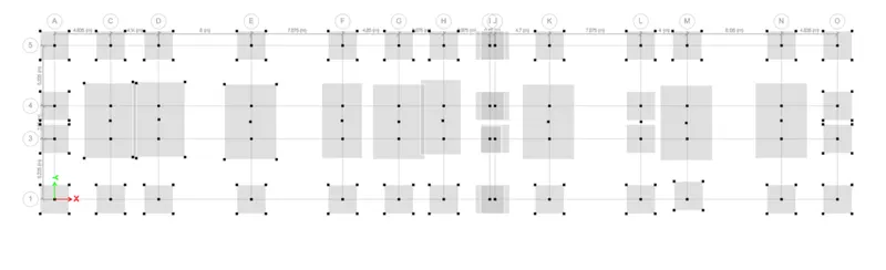
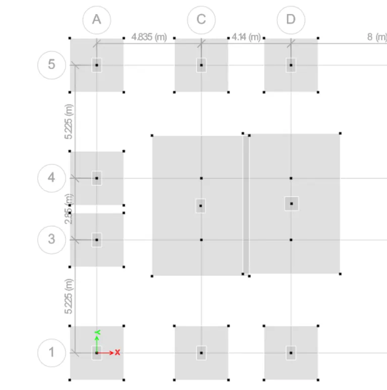
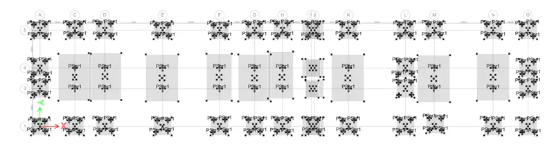
- Add piles at the point
- Modify the edge distance to 0.2m
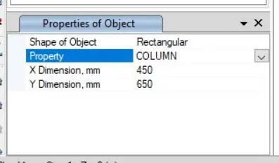
- Create a column of 450 x 650 mm, as shown below.
- Draw the column in the center using the quick draw tool
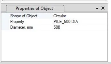
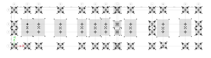
- Select pile > assign > support data > point springs.
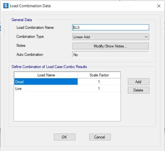
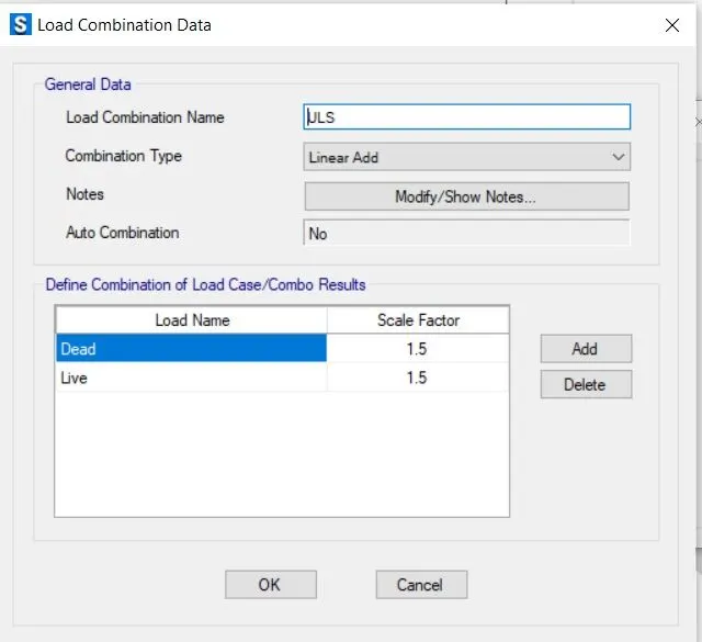
- Load case combination was defined, as shown below.
- After defining the load combination Run the analysis.
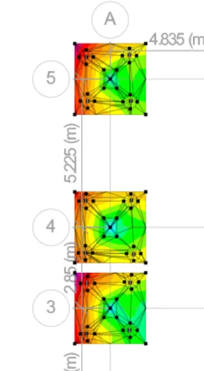
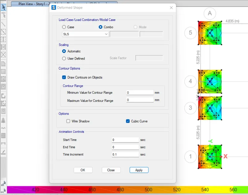
CHECK FOR SETTLEMENT:
-According to the codebook a total settlement of 25 mm is allowable not more than that. So the allowable settlement in our case is less than the permissible allowable limit. Hence OK.
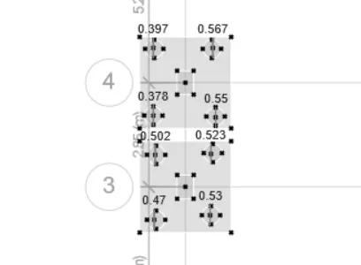
CHECK FOR PUNCHING SHEAR:
- According to the IS code the punching value should not cross the unit value, so in our case, the punching shear value is less than the unit value. Hence OK.
- Reinforcement Slab Design.
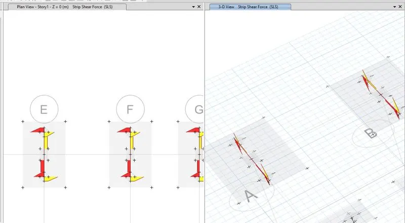
The Hostel building has been designed and analyzed by the SAFE software successfully.