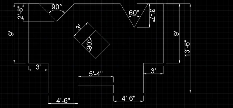
Drafting of various geometries using Chamfer, Fillet tool in AutoCad
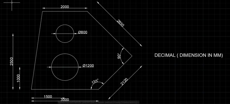
1. AIM: To create geometries using the given command
PROCEDURE:
1. Change the unit to decimal and MM
2. Draw the outer boundary with the help of a line command
3. Use the relative Rectangular method and relative polar method for the outer boundary
4. Now use the circle command to draw the circle inside the geometry
5. Lastly use the dimension command to determine the length and angle of the geometry
RESULT:
2. AIM: To create geometries using the given command
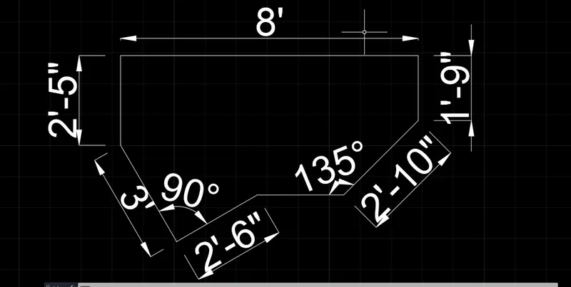
PROCEDURE:
1. First change the unit to engineering and feet
2. Use the line command to draw the Boundary of the geometry
3. Use both Relative Rectangular and Relative polar methods to draw the line
4. Lastly use the Dimension command to determine the length and angle of the geometry
RESULT:
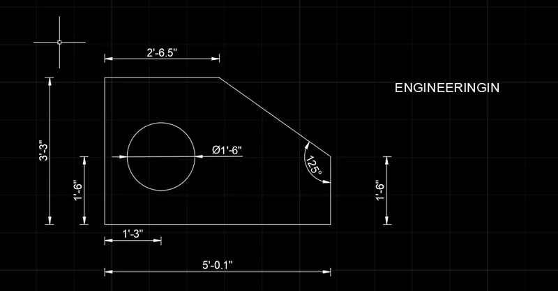
3. AIM: To create geometries using the given command
PROCEDURE:
1. First change the unit to engineering and feet
2. Use the line command to draw the boundary
3. Use the Relative rectangular method and make sure to on polar command to track the angle in the required direction
4. Use the circle command to draw the circle with the help of the center point
5. Now use the dimension command to determine the dimension of the geometry
RESULT:
4. AIM: To create geometries using the given command
PROCEDURE:
1. Change the unit to decimal and meter
2. Now with help of the line command draw the outer boundary of the geometry
3. Use the relative rectangular method to draw the line
4. lastly use the dimension command to determine the dimension of the geometry
RESULT:
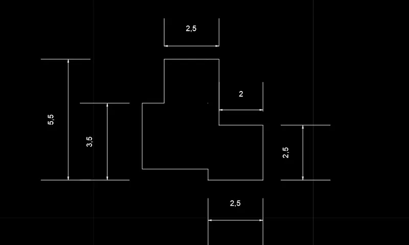
5. AIM: To create geometries using the given command
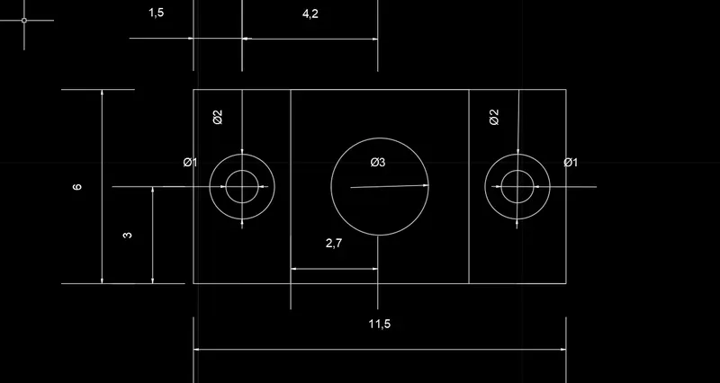
PROCEDURE:
1. Use the decimal and meter as the unit
2. Use the line command to draw the outer boundary of the geometry
3. Use the Relative rectangular method for drawing the boundary
4. lastly use the dimension command to determine the dimension of the geometry
RESULT:
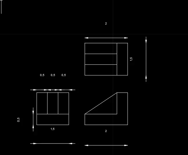
6. AIM: To create a top, front, and side of the geometries using the given command
PROCEDURE:
1. Change the unit to Decimal and meter
2. Use the line command to draw the geometry
3. Use the relative rectangular method to draw the geometry
4. draw the side, front, and top view of the geometry
5. Lastly use the dimension command to determine the dimension of the geometry
RESULT:
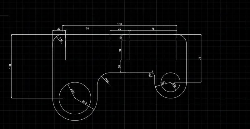
7. AIM: To create geometries using the given command
PROCEDURE:
1. Change the unit to decimal and meter
2. Draw the boundary of the geometry by using the line command
3. Draw the circle with the help of the circle command
4. make the edges curvy with the help of the fillet command using the given dimension
5. Trim off the Excess line which is not need
6. Use the dimension command to determine the length, radius, and diameter of the geometry
RESULT:
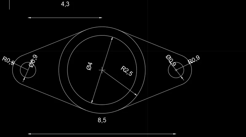
8. AIM: To create geometries using the given command
PROCEDURE:
1. Use the Decimal and meter ans the unit for this geometry
2. Draw the required circle needed for the geometry with the required distance and dimension
3. Connect the outer edge of the circle with the help of a line command
4. Draw a tangent and connect the circle
5. Trim the excess quantity of unwanted lines and length
6. Use the dimension command to determine the length, radius, and diameter of the geometry
RESULT:
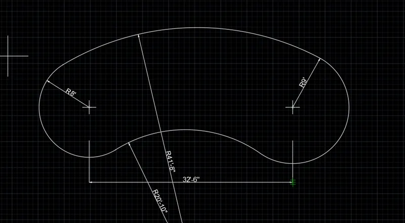
9. AIM: To create geometries using the given command
PROCEDURE:
1. Change the unit to engineering and feet for this geometry
2. Use the circle command to determine the 2 normal required circle
3. Now use the Circle command however use tan, tan, and radius to draw a circle
4. Draw the circle tangentially to both the circle
5. Trim off the unwanted length
6. Use the dimension command to determine the length and radius of the geometry
RESULT:
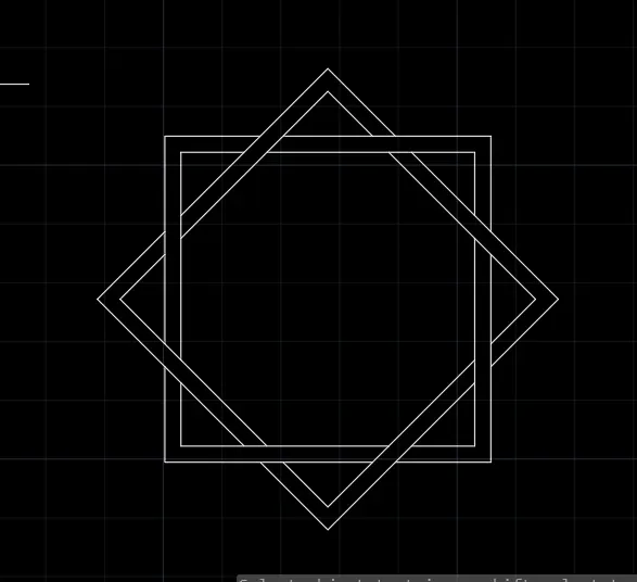
10. AIM: To create geometries using the given command
PROCEDURE:
1. Draw the rectangle using the polygon command
2. Take the offset of that rectangle
3. Copy that geometry and rotate it with the help of rotate command for the required angle
4. Then place it over the previous geometry
5. Use the trim command to trim off the excess line
RESULT:
11. AIM: To create geometries using the given command
PROCEDURE:
1. Change the unit to Engineering and feet
2. Draw the Boundary of the given geometry
3. By using the Relative rectangular method
4. Keep the polar command on to determine the angle in the given geometry
5. Now draw a rectangle by using the rectangle command
6. change the Rotation of the rectangle by using rotate command
7. And move it to the Centre of the geometry with the help of the move command
8. Determine the dimension by using the dimension command
RESULT: