Project 2_Design & Analysis of a Hostel building at Guwahati, Assam
AIM- Complete the Project of Hostel Building (G+3) In Guwahati Assam
Objective of the challange
- To Calculate and assume necessary data from the given architectural and site information
- To Model analysis and design he frame structural using ETABS
- To model analysis and design the foundation using SAFE software
- To produce structural typical floor plan & Typical rebar drawings of memebers
Data Given For the Project
- Building Type = Hostel Academic
- Location = Assam Guwahati
- Seismic Zone =5
- Soil Type = 3
Data required for the ETABS analysis of model
- Pinned support base + 5 story (Plinth to roof)+ 1 Mumty level
- Columns 650x450
- Beams 400x500
- Slab 150mm Thick
Loads values As per the Code 875 (part 1&2)
- Floor live load =2 KN/m^2
- Terrace live load= 1 KN/m^2
- Floor finish + celling Finish =2 KN/m^2
- Partition wall load = 3 KN/m
- Balcony wall Load 1 KN/m
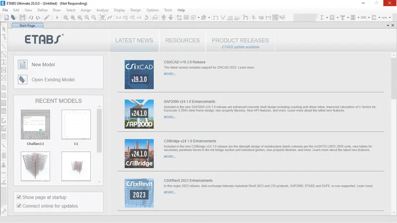
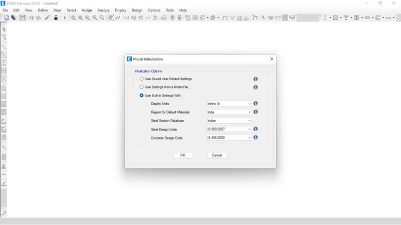
Open Etabs
Grids spacing values
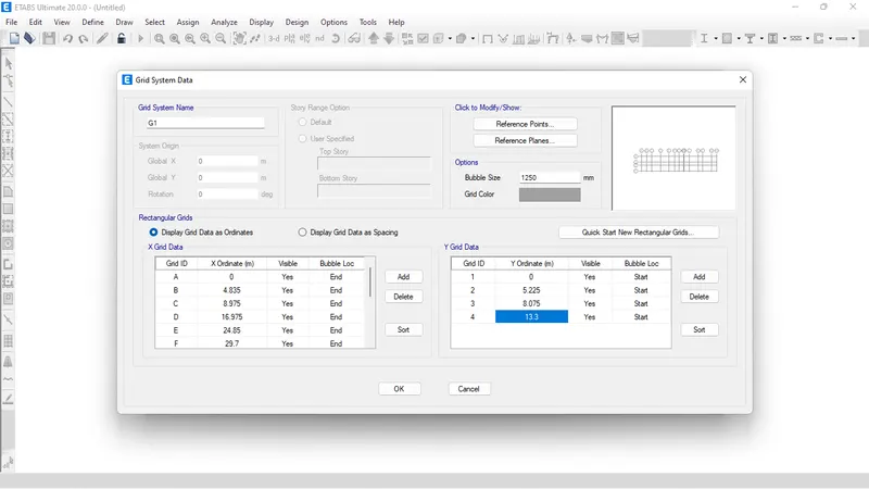
Now Click OK and Start modelling
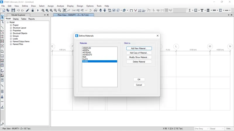
- Define Materials = Fe500 and M25
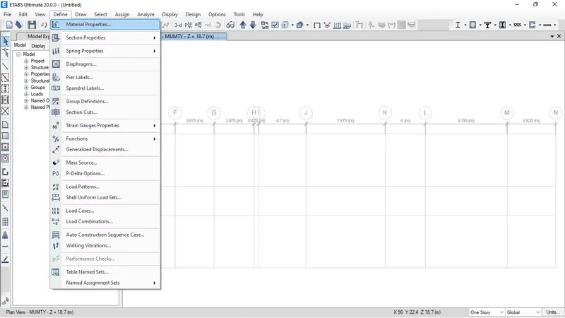
- Define Frames
Beams 400x500mm and Columns 650x450mm
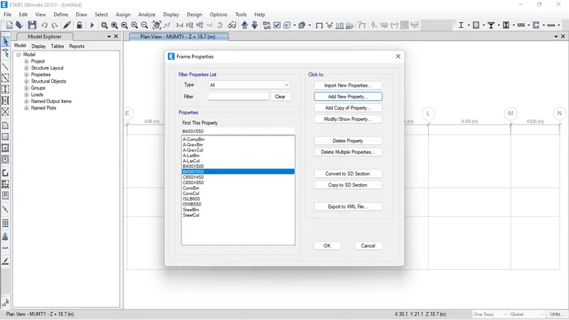
For column Section
450x500mm Size and M25 Fe500&415 Assigned and than mass in X&Y Direction As 70%
For Beam Section
400x500 mm Size and M25 Fe500&415 Assigned and than mass in X&Y Direction As 35%
For slab section
150mm Thickness as membrane and M25 Fe500&415 Assigned
Define Loads
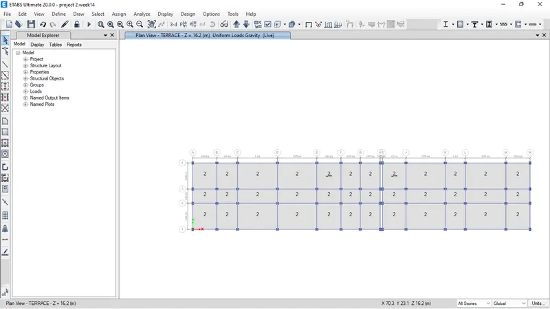
Model Prepared in Etabs by draw all the columns and Beams and Slab sections
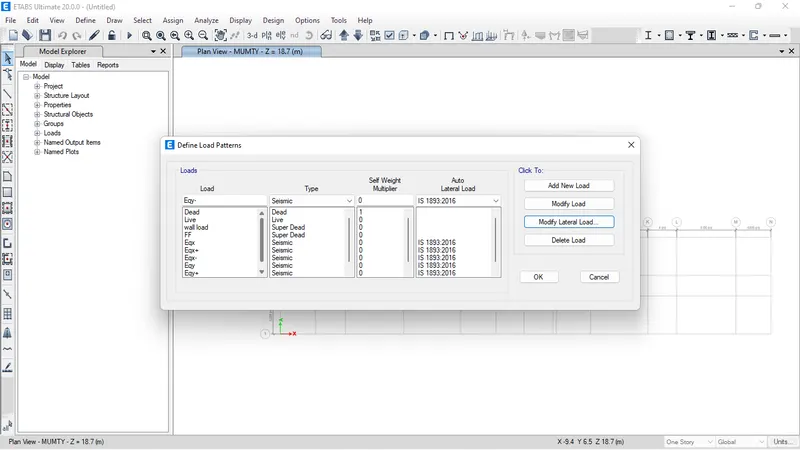
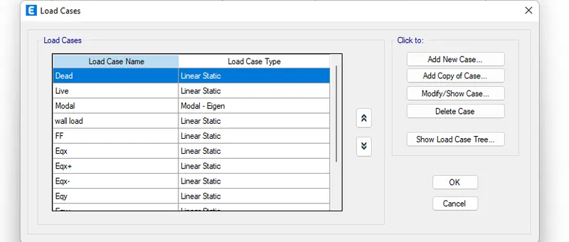
Defining of variuous Load Cases
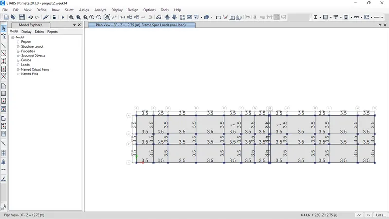
Floor Live Load Terrace live load is designed as live loads and wall and finishes assigned as superdead loads in load definition
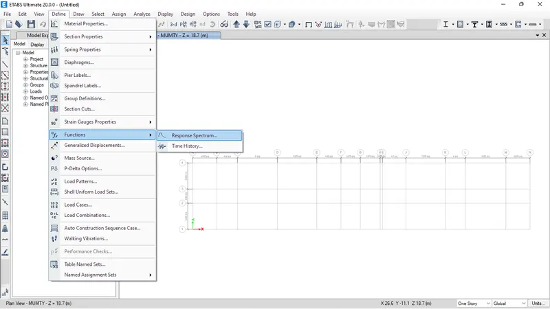
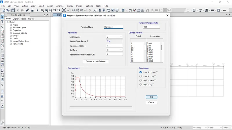
- Respose spectrum defined for the zone V and the type 3 soil other factors considered as default.
Now Assigning of Various Load as described above are assigned to Frame loads and shell Loads
Afer that assign the loads Mass source and diaphram and Check model then Run analysis get the Following Results
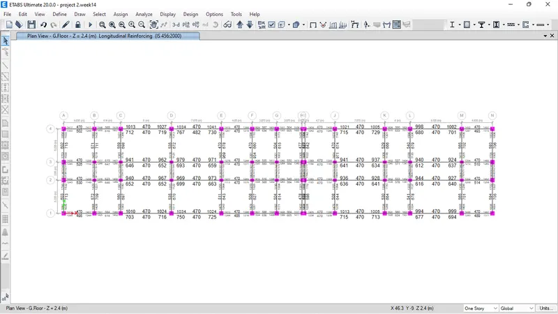
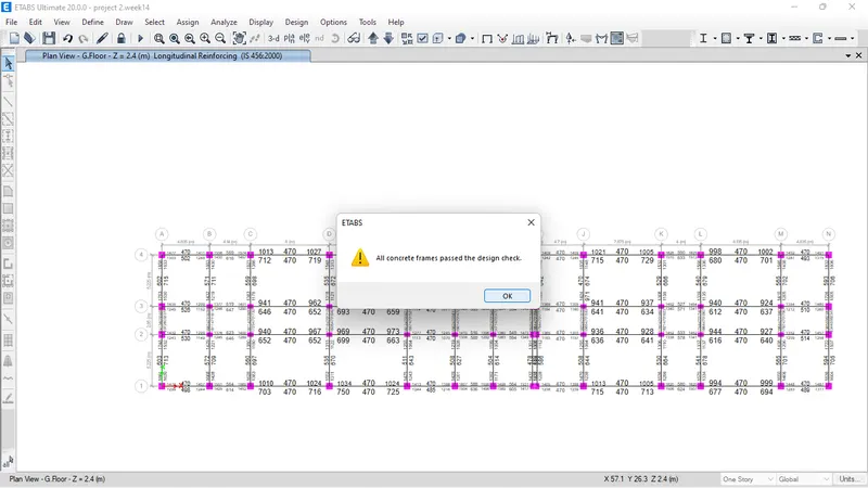
Check if all passed or not.
looks like all members passed in design chek.
So the further checks are done for the Model
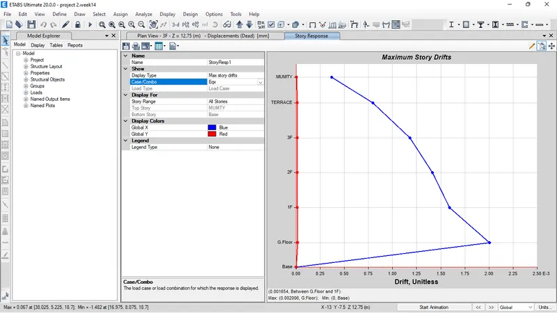
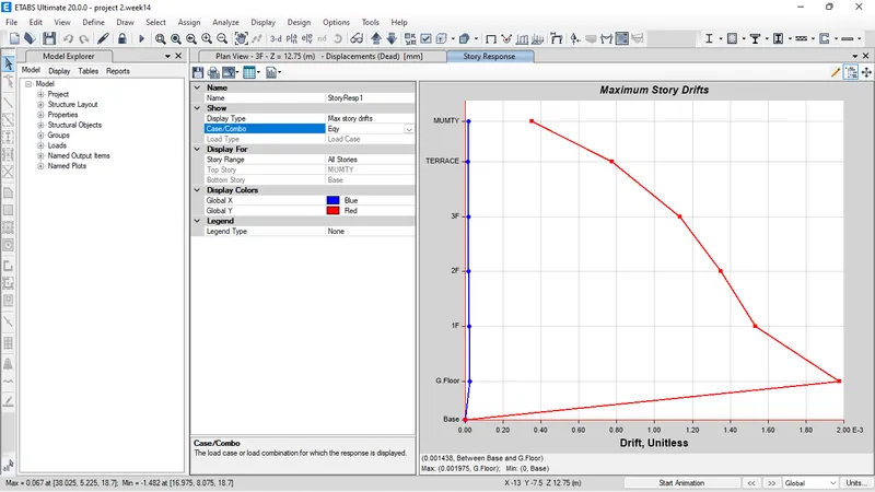
Check of Drift of Model in X and Y direction Due to the seismic Forces in X and Y directions
Storey Response plot is below for maximum drift due to the Eqx and Eqy
Response inY
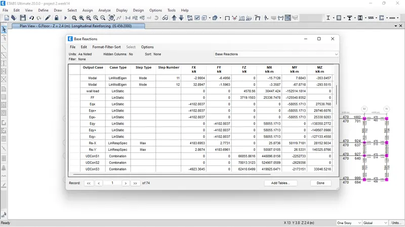
Following Base reactions are obtained due to loads
Now have to design the Reinforcement For the typical Beam and Columns
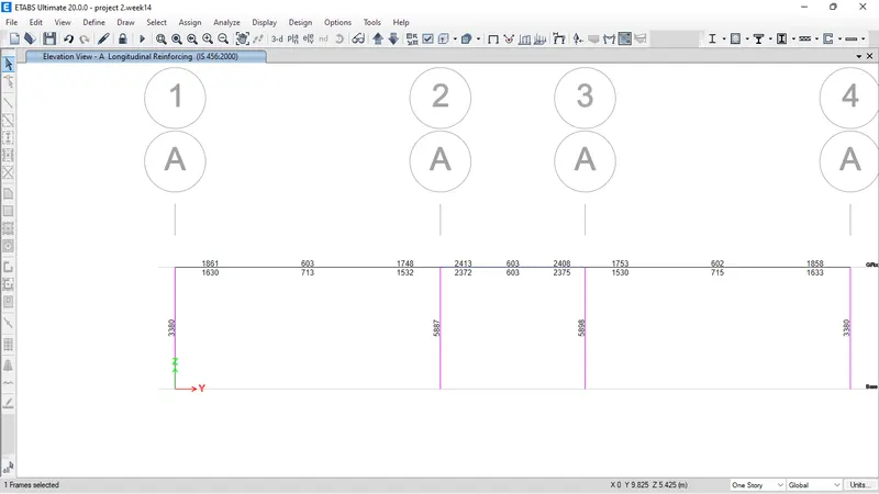
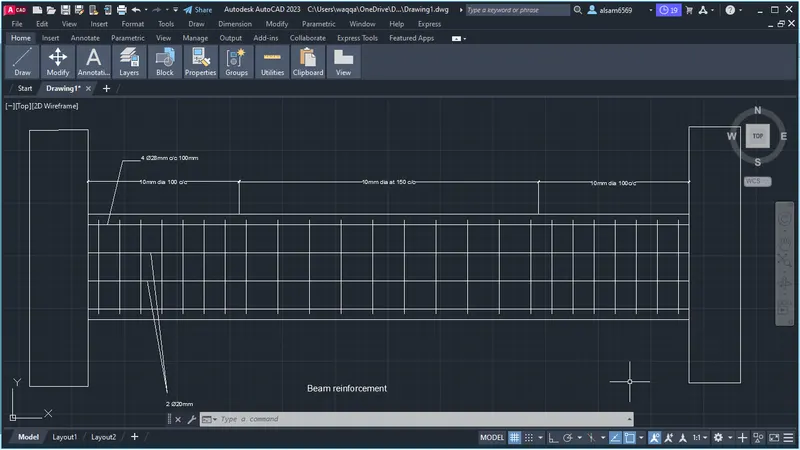
Reinforcement Required for the Beam section A-3 to A-4 only
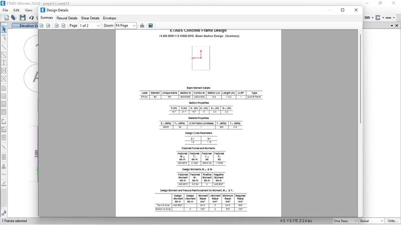
So The Reinforcement Calculations
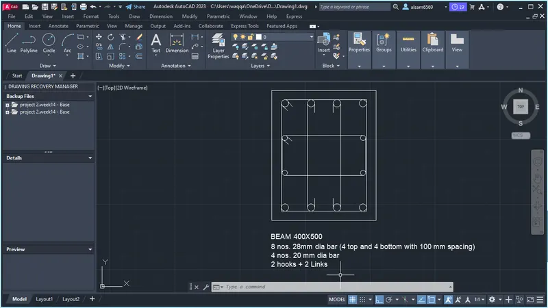
Beam top Reinforcemet
required= 2413
32mm bar dia area = 615.44 mm
= 615.44x4 =2461.76
so 4 bar 28mm dia at top
middle top
required= 603
20 mm dia bar x2 = area of bar x no. of bar = 314x2 = 628mm
Bottom reinforcement bar
required= 2375
4 bar of 28 mm dia
Reinforcement Required for the column A-1
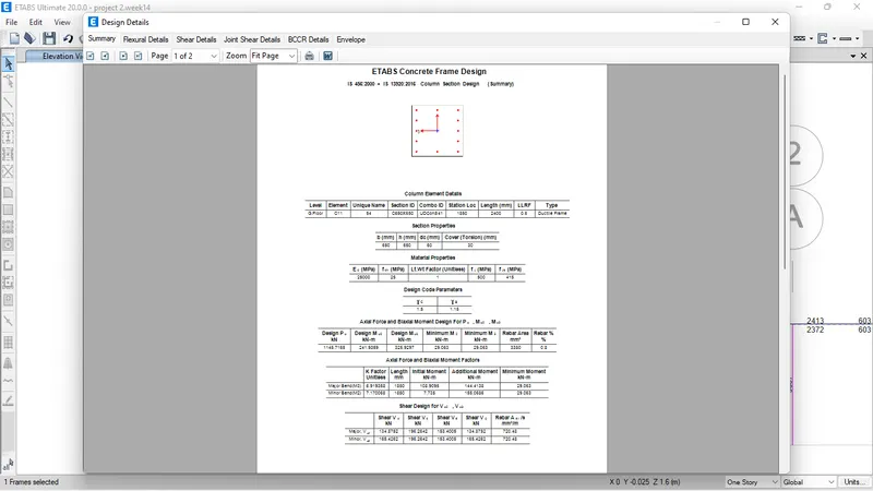
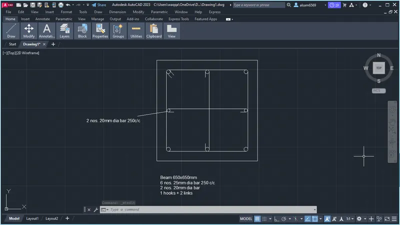
Reinforcement Calculation
Required reinforcement= 3380
25 mm dia 6 bar and 20 mm dia 2 bar = 490x6+314x2
= 3568
Now To Export the Model and design the Pile Foundation
File exported as Story F2K File With BASE>ALL cOMB>ALL LOADS
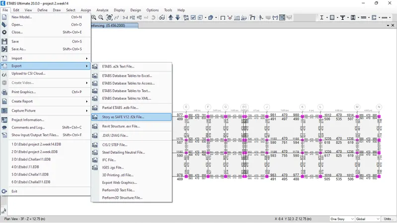
Than Open SAFE> New model>Blank> import >select file
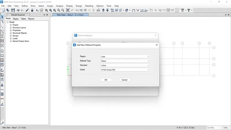
Than Define Material as M25 &fe500
Section
Plie CAP=MAT>800mm Thickness
Pile 500=Mat>800mm Thick@500Dia
Columns=Stiff >800 Thick
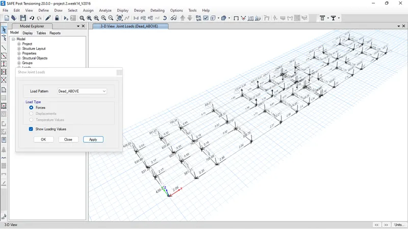
As on the basis of those above reactions I can create number of piles-
FOR Exam. COLUMN NUMBER (D3):
AXIAL LOAD = 783 kN
Length of piles 10m
Diameter of pile = 500mm
Pile capacity = 280KN.
NO . OF PILE = 958/280 = 3.4 = 4 Pile
Grade of concrete is M25
Area of each pile A =`pi/4doverset2`= 3.14/4 x500 x500 = 196250mm`
E = 5000fck">√fck= 25000
Spring constant (k) `= EA/L = (25000 x 196250)/10000 = 490873.75 N/mm = 490873.75 KN`
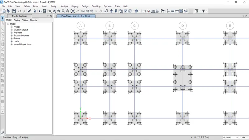
DRAWING TIE BEAMS
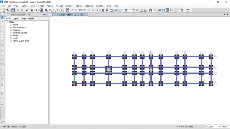
After drawing all pile cap and piles assign the POINT SPRING AS =490.87
RUN THE ANALYSIS AND FOUND THE RESULTS
RESULTS
cHECK FOR PUNCHING SHEAR
SETTELMENT OF PILE
DESIGN STRIPS FOR THE REINFORCEMENT CALCULATION
Punchin is within limit 1
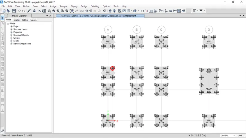
forces in Tie Beams
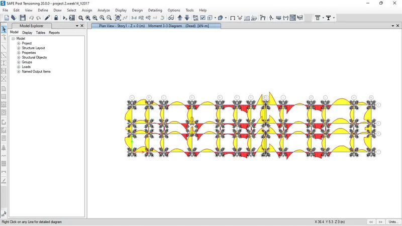
Result = Succesfully Design and Analyse the Hostel building many corrections are needed to do exact design its just the procedure to Model Design and analysis with the softwares ETABS & SAFE