Project 2_Design & Analysis of a Hostel building at Guwahati, Assam
Question:-
In this project, participants will get to experience the entire design process from modelling, analysis, design, and preparation of construction drawings. The architectural drawings of a G+3 RCC building is provided. The following information on the building is to be used:
- Location – Guwahati, Assam
- Function – Hostel block in an academic institute
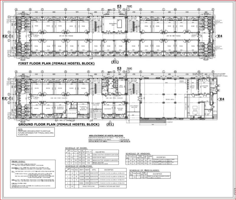
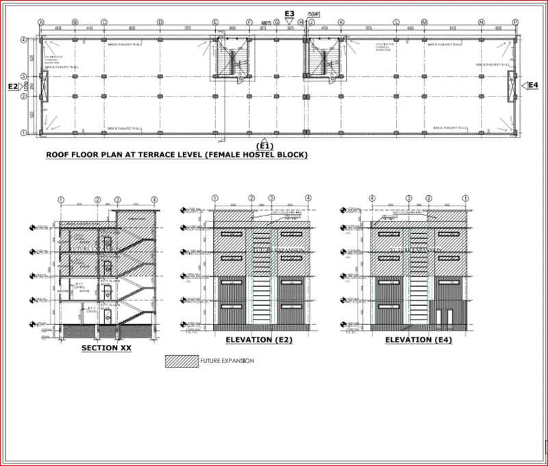
The walls will be made of AAC blocks. Other loadings are to be calculated as per the architectural drawings.
The buildings rests on type 3 soil. Piles of length 10 meters and 500 mm diameter with a load-carrying capacity of 280 KN is to be used.
The ground floor level will be at a height of 2 meters above the existing site level to avoid floodwater enter the building.
M25 grade of concrete with Fe500 for longitudinal reinforcement and Fe 415 for shear reinforcement is to be used.
The following design IS codes will be required for reference:
- IS 875 part 1
- IS 875 part 2
- IS 13920
- IS 1893
- IS 2911 part 2
- IS 456
- SP 34
Students will have to produce the following:
- Etabs model for the two blocks on either side of the expansion gap
- Foundation details illustrating the pile & pile cap reinforcement
- Tie beam details connecting the pile caps
- Column reinforcement
- Framing plan for typical floor
- Beam reinforcements for ground floor
Answer:-
Aim:-
To Model, Analysis and design the Frame structure using ETABS Software & Foundation using SAFE Software.
Introduction:-
- ETABS is an engineering software product that helps to analysis and design the multi strorey building.
- SAFE represents the state of art in three dimensional finite element technologies for structural engineering.
- Here, in this project we are carrying out the design analysis of a G+3 RCC building situated in Guwahati, Assam using ETABS software and then foundation design is carried out using SAFE software.
Building Design:
Given Data:
1) Location – Guwahati, Assam. It is Located in the Seismic Zone V.
2) Hostel block in an academic institute
3) Walls are made of AAC Blocks. Hence, Wall load to be 4.5kN/m.
4) Concrete - M25 Grade
5) Longitudinal Reinforcement - Fe500
6) Shear Reinforcement - Fe415
Lets Assume,
- Building is Pinned Support at base.
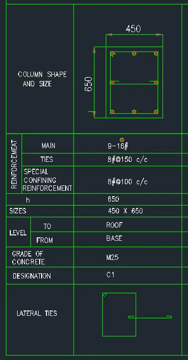
- Column - 450 x 650mm, Beam - 400 x 500mm, Slab - 150mm and Slab at Staircase - 200mm.
- Floor Live Load - 2 kN/m2, Terrace Live load - 1 kN/m2, Floor Finish + Ceiling Finish - 1 kN/m2, All Partition wall load - 3.5 kN/m and Roof Balcony wall load - 1kN/m.
Procedure:-
Step 1:-
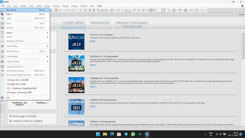
- Open ETABS Software, and select New Model from File Tab.
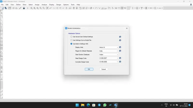
- A Model Initialization window opens, in that giev input as shown below.
- Then New Model Quick Templates window opens, Now select Custom Grid Spacing and Edit Grid Data.
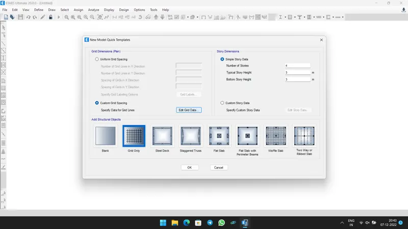
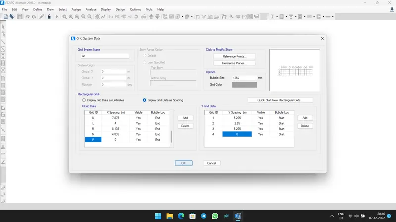
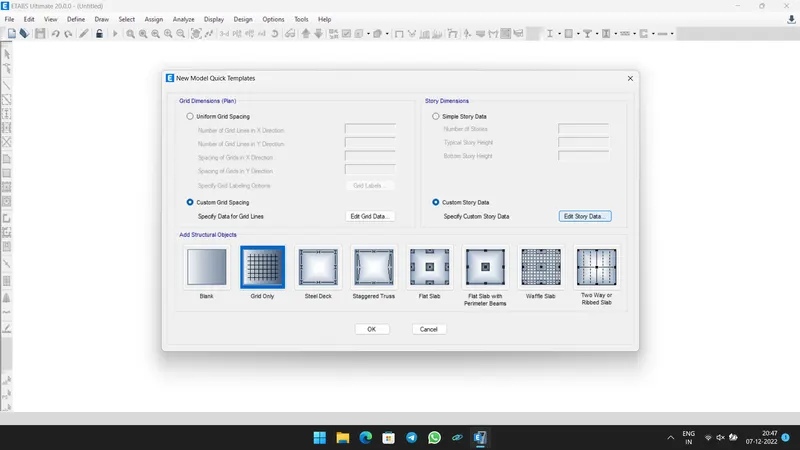
- Now select Custom Story Data and set Story data as shown below.
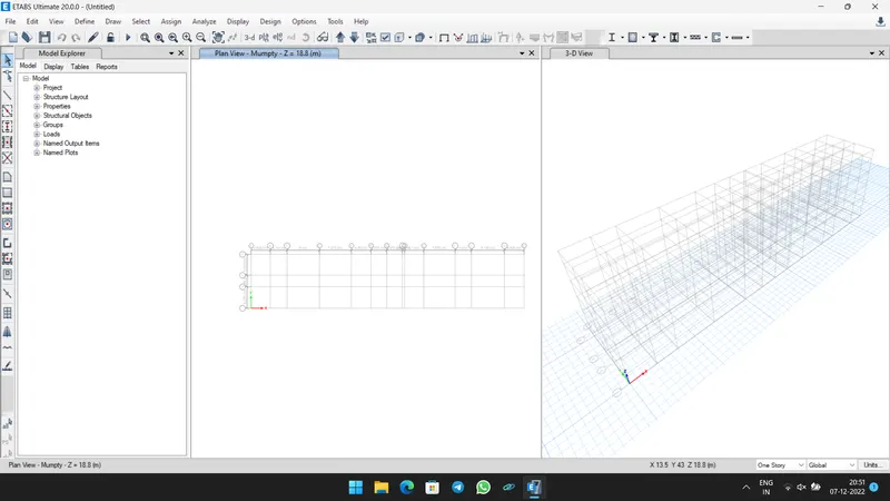
- Model Grids and level created succesfully.
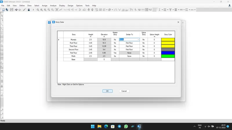
Step 2:-
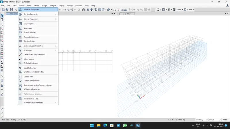
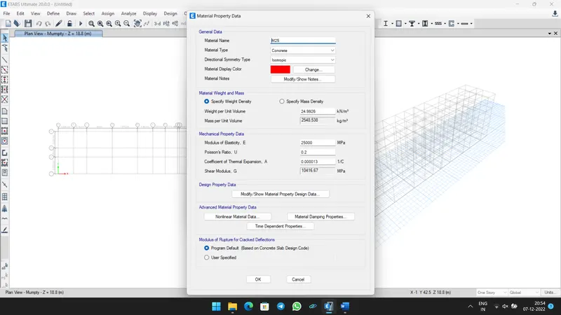
- Now Select Material Properties from Define Tab. And click Add New Material.
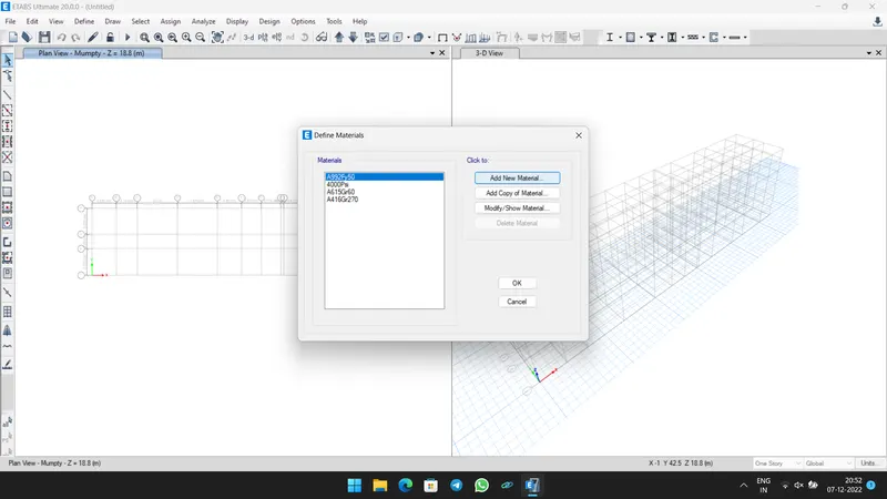
- Define Concrete Grade as M25 as shown below.
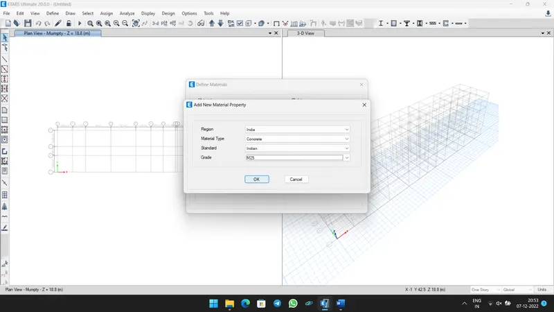
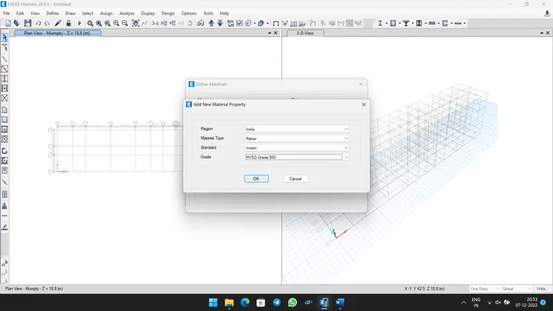
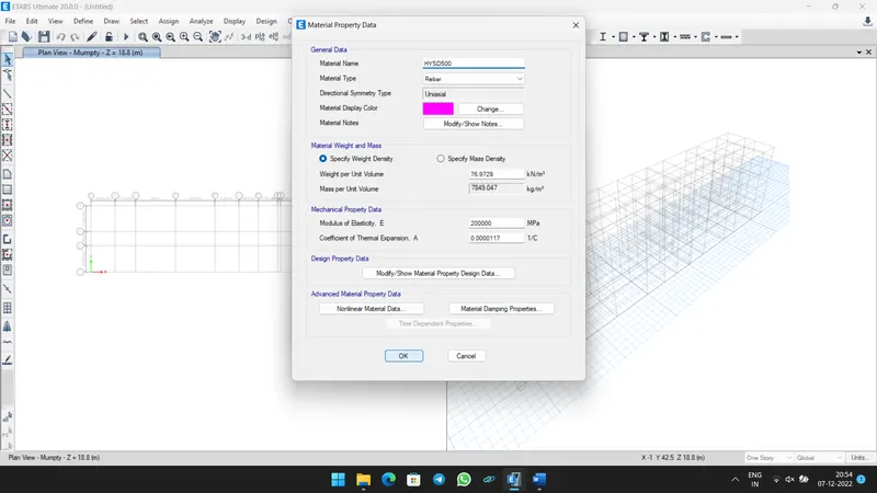
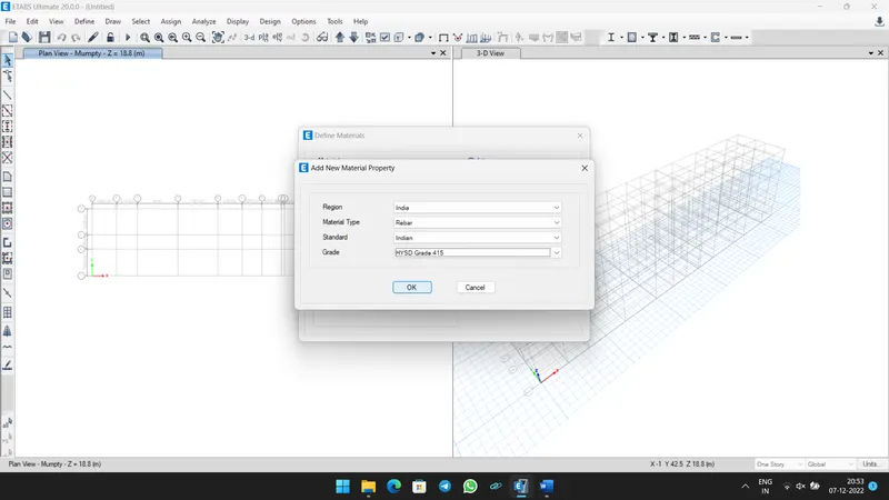
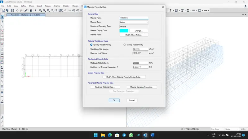
- Similarly Define Rebar Grade as Fe500 and Fe 415.
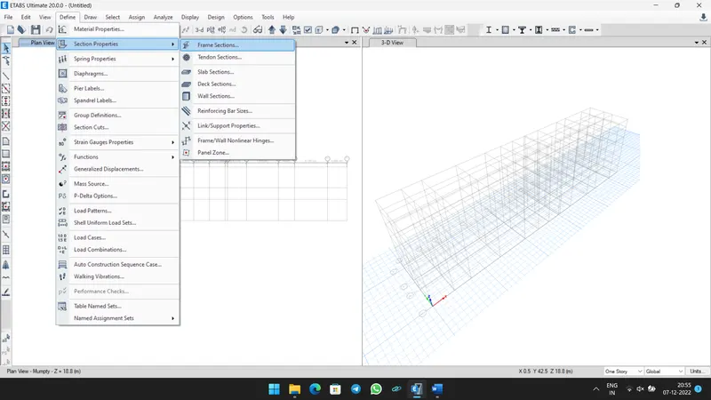
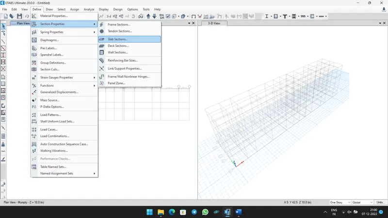
- Then Define Section Properties under Define Tab, Select Frame Sections as shown below.
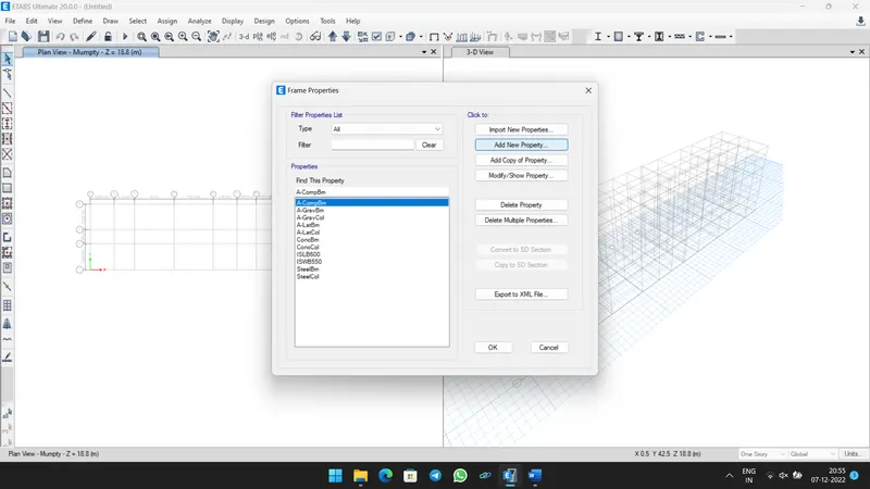
- Click Add New Property and Select Rectangle Section.
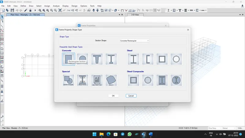
- Define Column Section as C450x650 and select material as M25.
- Then Click Modify/Show Rebar and select P-M2-M3 Design (Column) as shown below.
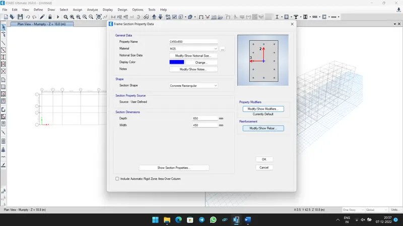
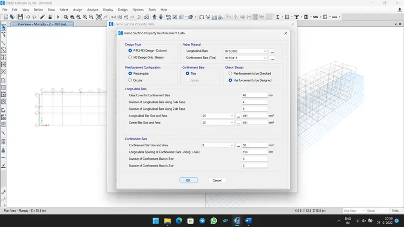
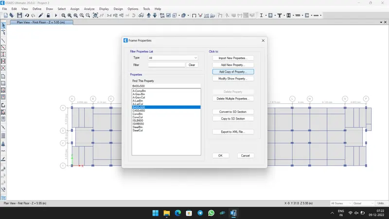
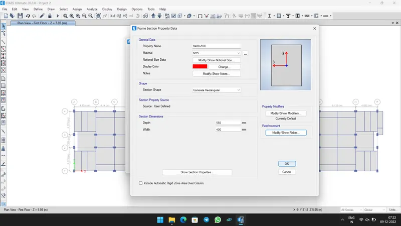
- Similarly define Beam B400x500 and modify Rebar.
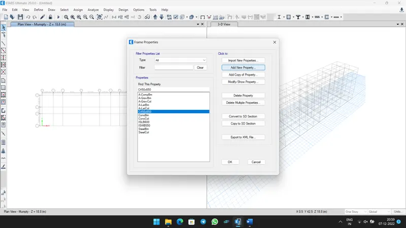
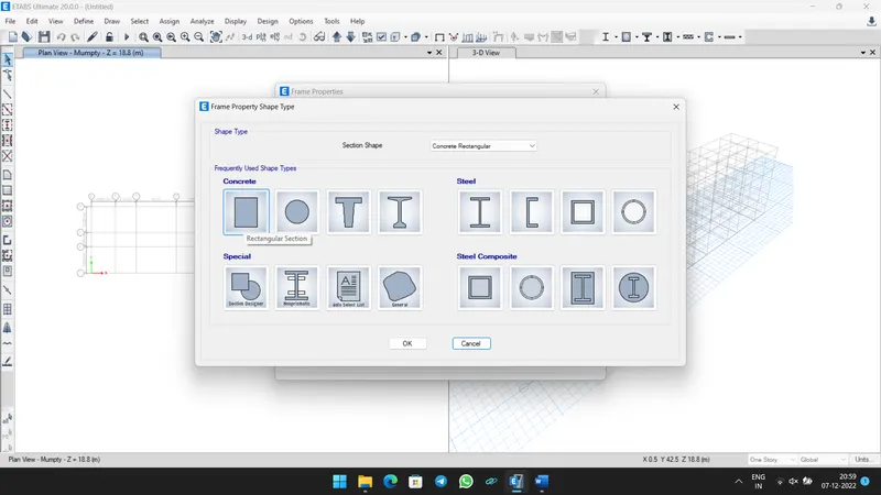
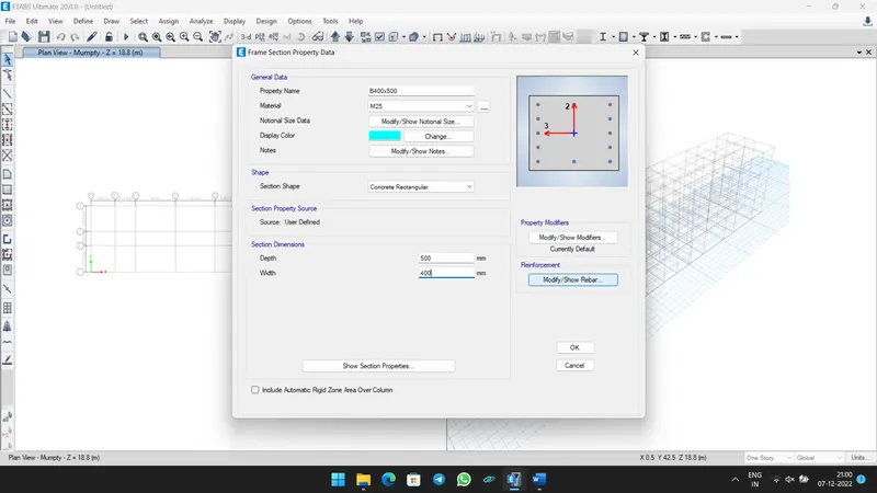
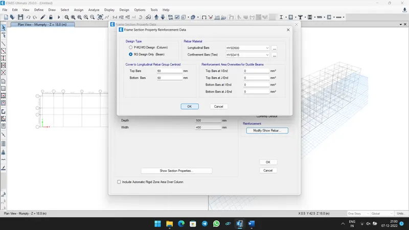
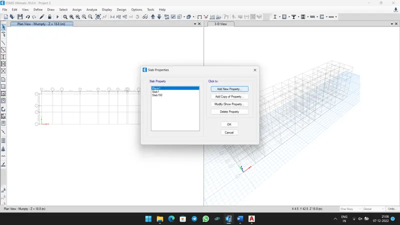
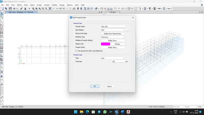
- Now Define Slab Sections, and give Slab thickness as 150mm for all slab and give 200mm thickness for Staircase slab.
Step 3:-
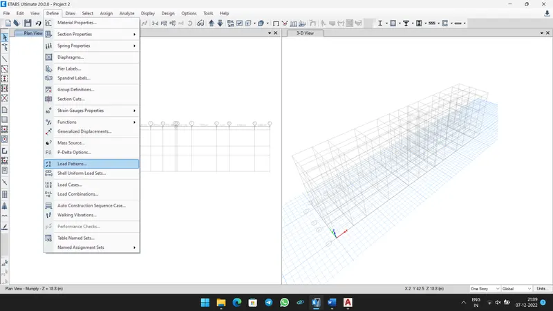
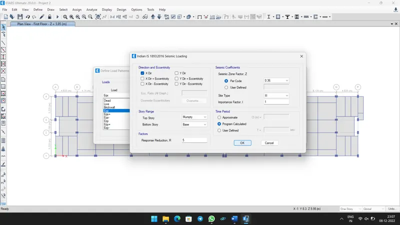
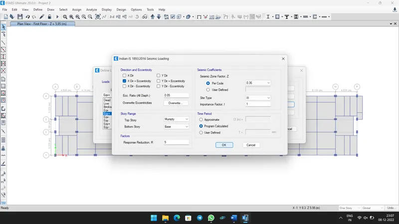
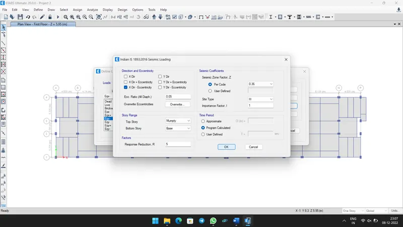
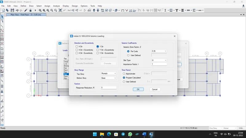
- Select Load Pattern in Define Tab, add Dead load, Live load, Brickwall load, floor finish load and
Earthquake loads in X and Y direction.
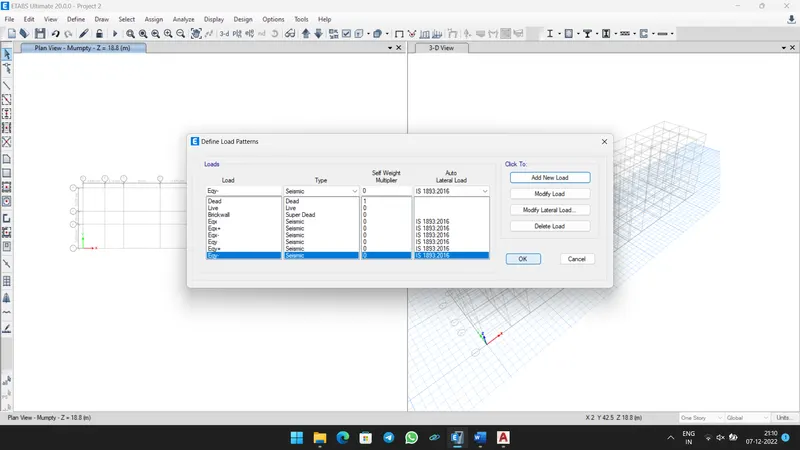
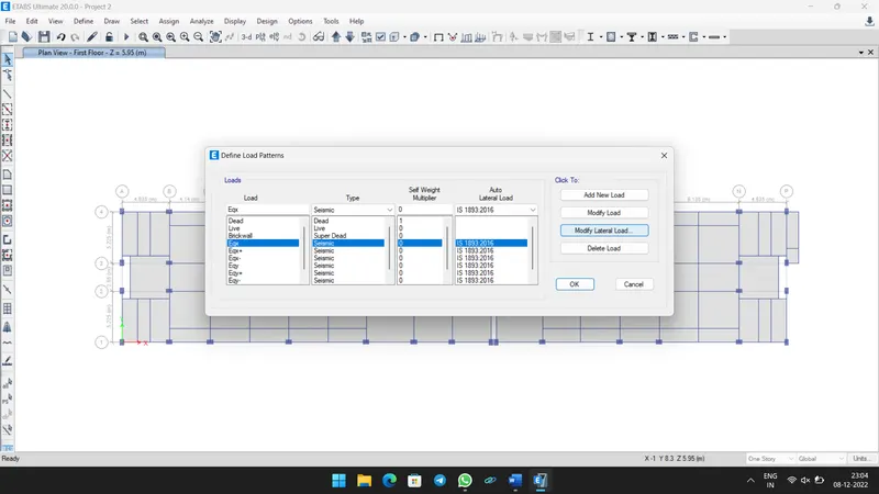
- Then Modify the Earthquake loads as shown below.
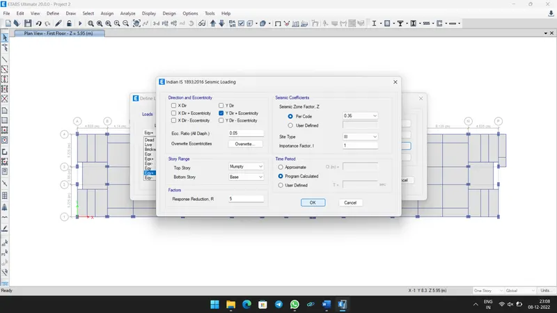
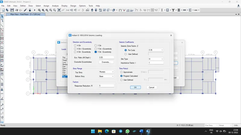
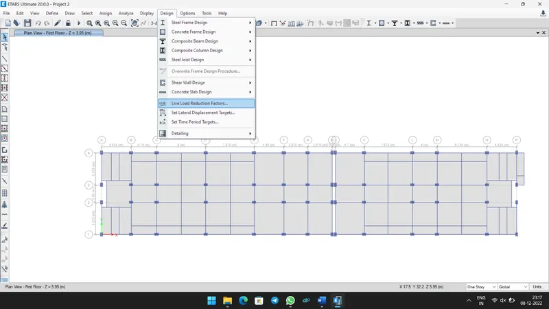
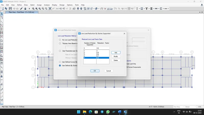
- Select Live Load Reduction factor under Design Tab.
- Reduce the loads by 10% for each floor as shown below.
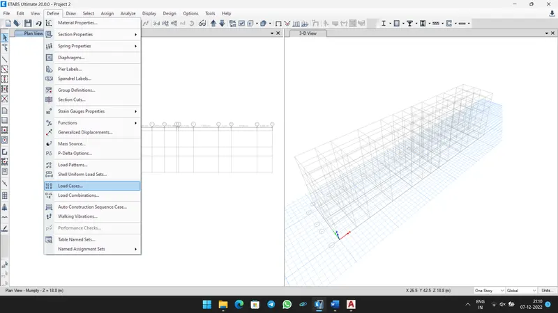
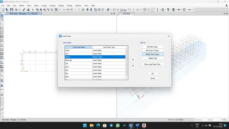
- Now go to Load cases from Define tab, select Modal case, then click Modify/ Show Case.
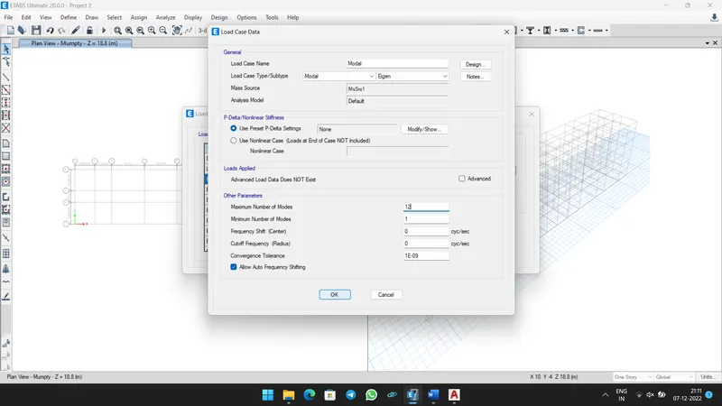
- Then Set the Modal Cases as shown Below.
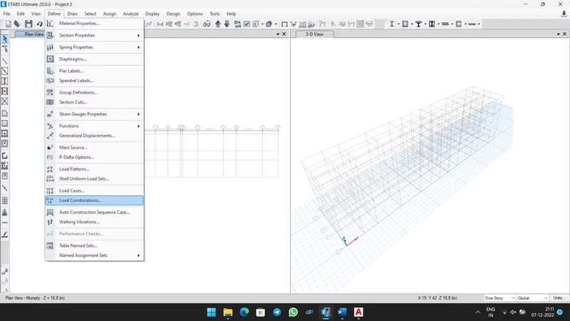
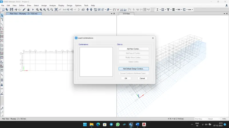
- Now select Load Combination, a pop-up window opens, in that select Add Default Design Combos.
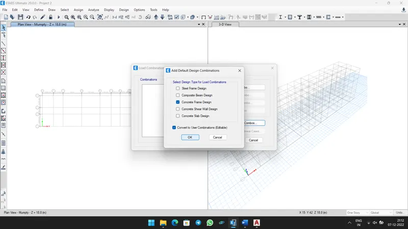
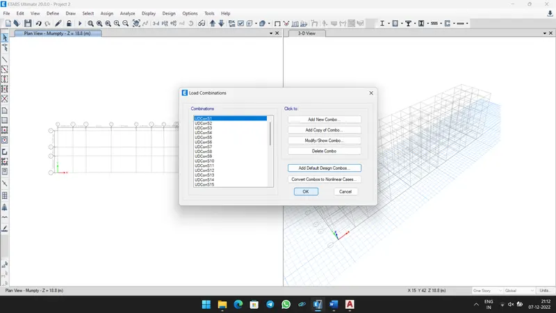
- Then Select Concrete Design Frame, Now Load combination automatically generated.
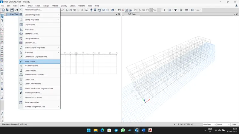
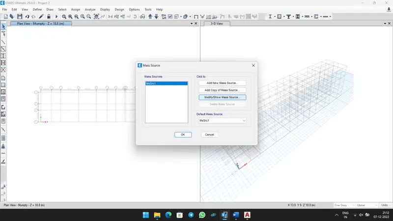
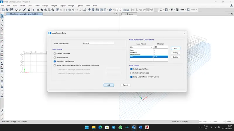
- Then Define Mass Source as Shown below.
Step 4:-
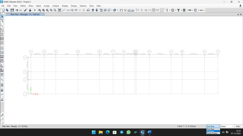
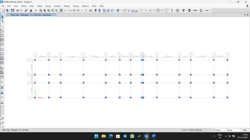
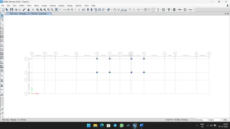
- To draw Column on Grids, first we need to select All Stories Option in bottom of window.
- Then Select Quick Draw Column icon in Draw toolbar.
- And select Column C450x650.
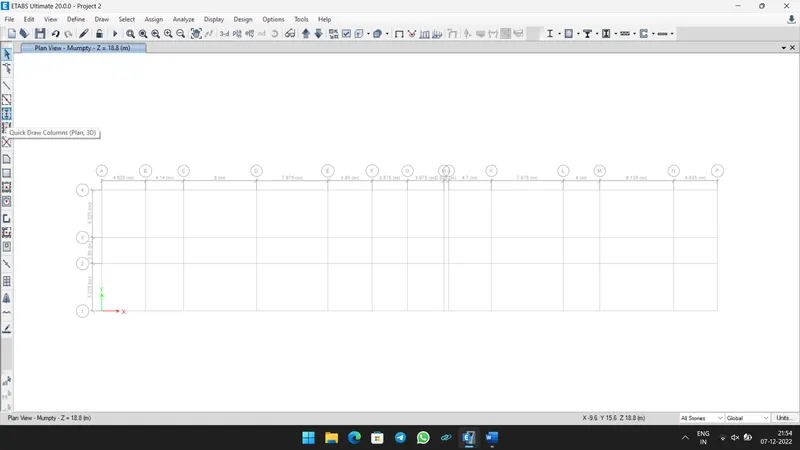
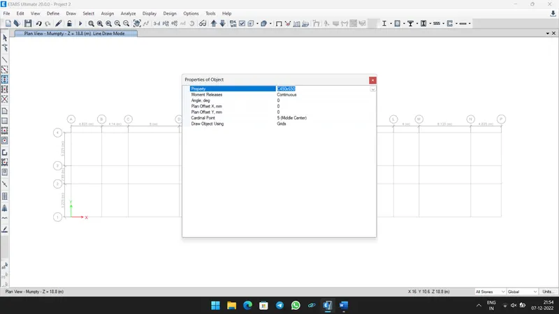
- Place the columns at its appropriate loaction as shown below.
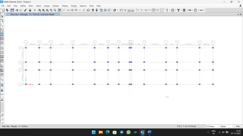
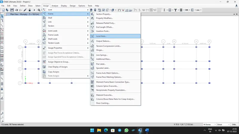
- Then Change the Rotation of column as required from Assign Tab.
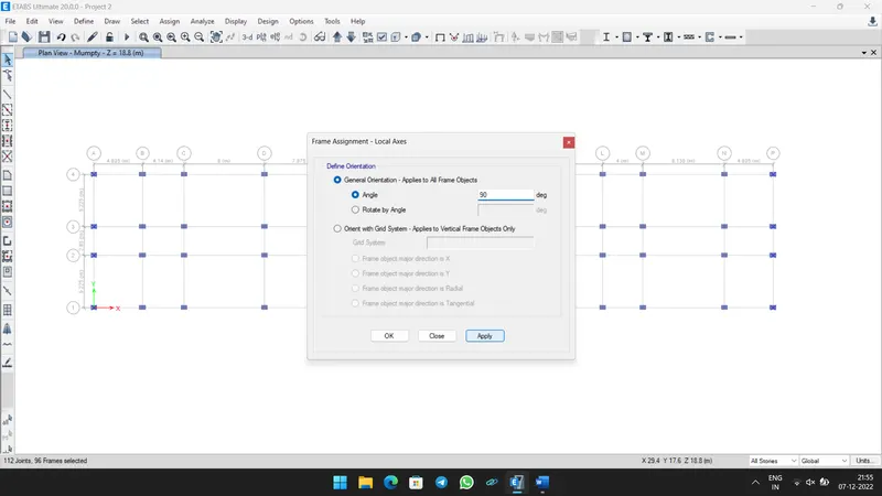
- Select Local Axes in Frame option, then change the angle as 90 degree as shown below.
- Now select the Quick Draw Beams/Columns icon in draw toolbar.
- Select the Beam as B400x500.
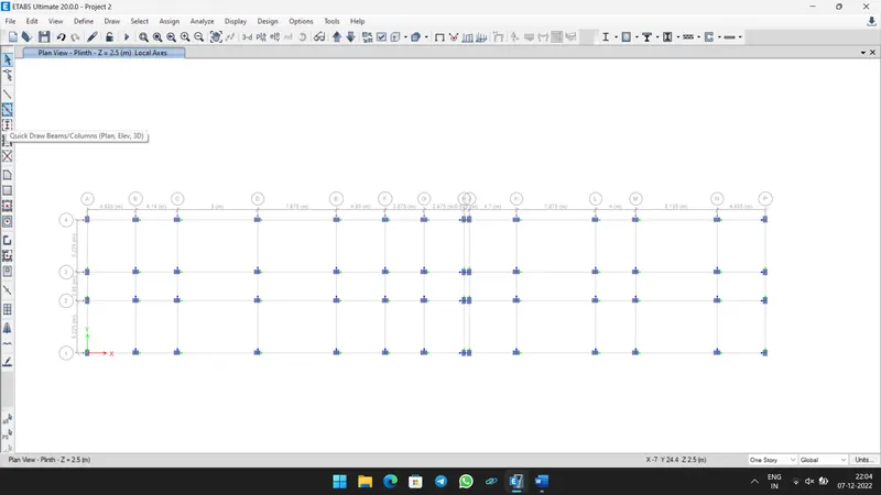
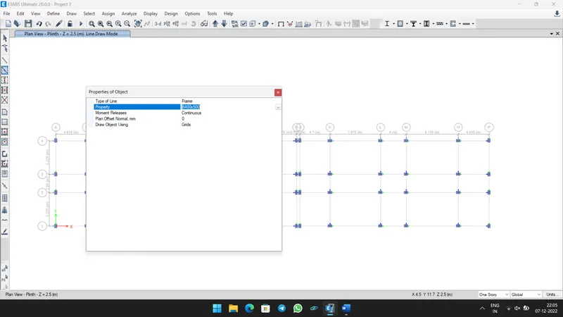
- Then Place the Primary beams at loaction.
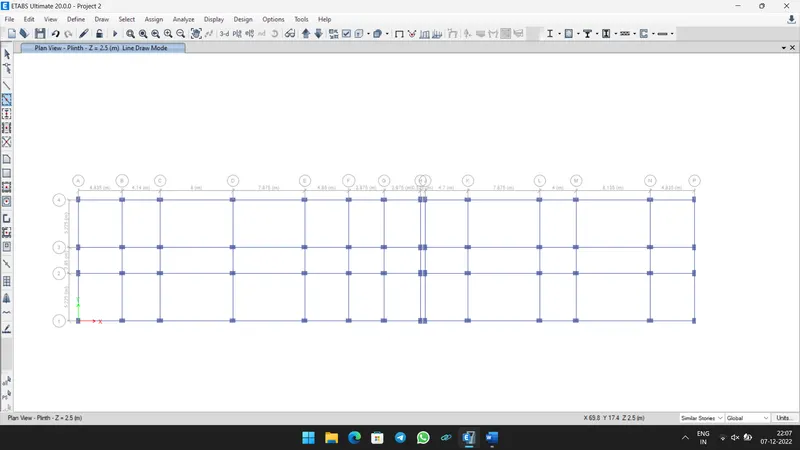
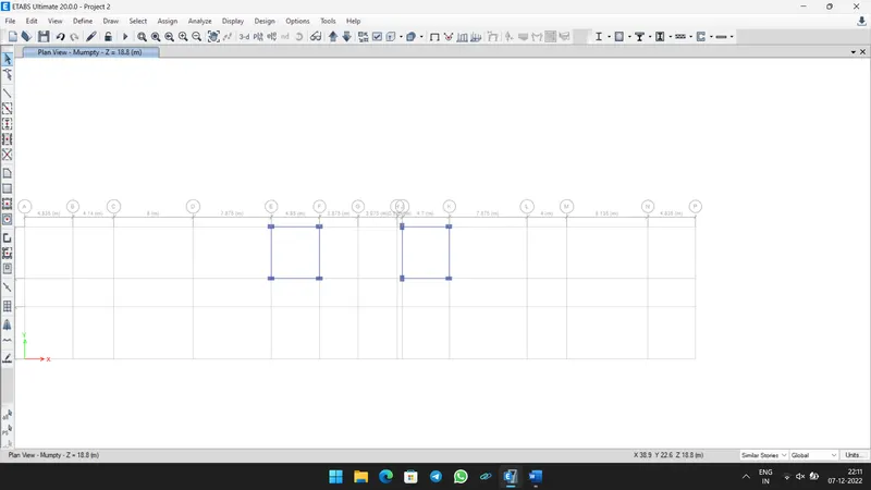
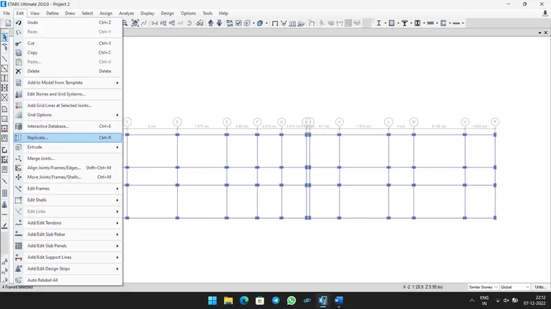
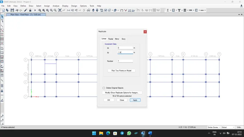
- Add Secondary Beams by using Replicate tool as shown below.
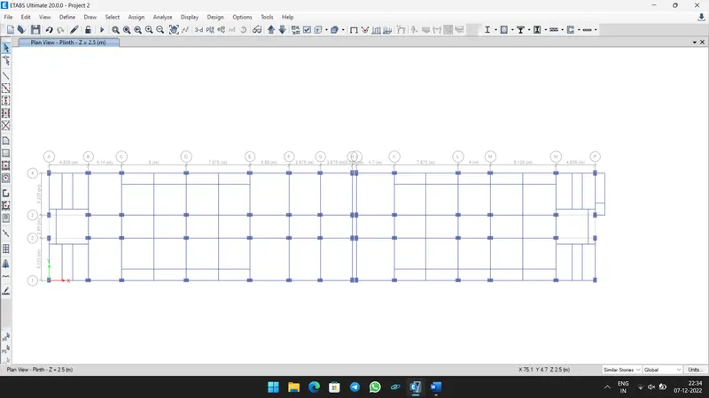
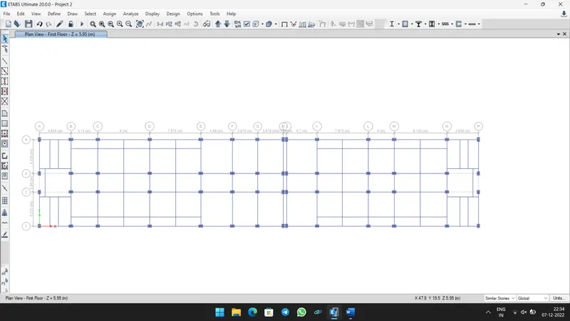
- Draw Floors by selecting the icon Quick Draw Floor/Wall tool.
- Then select Slab 150.
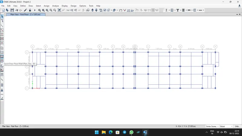
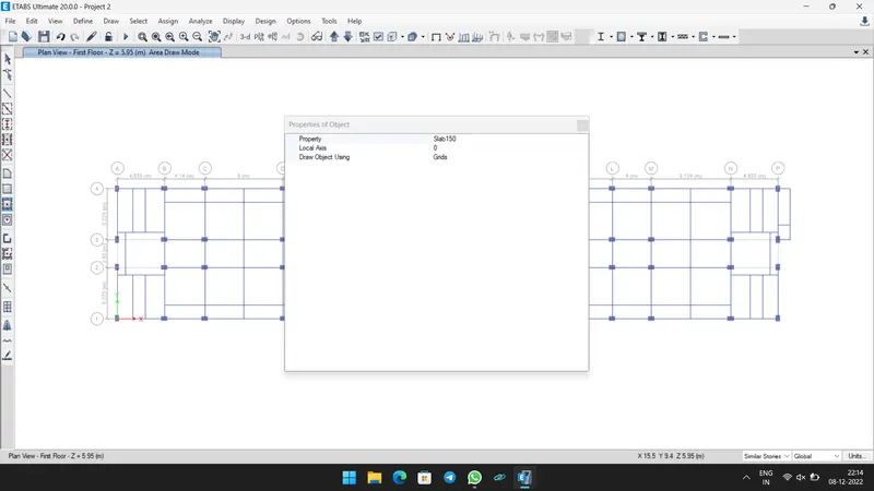
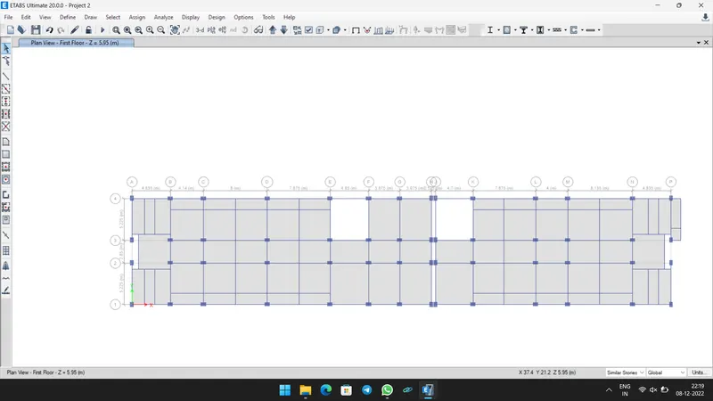
- Similarly draw Staircase slab by selecting Slab-STR.
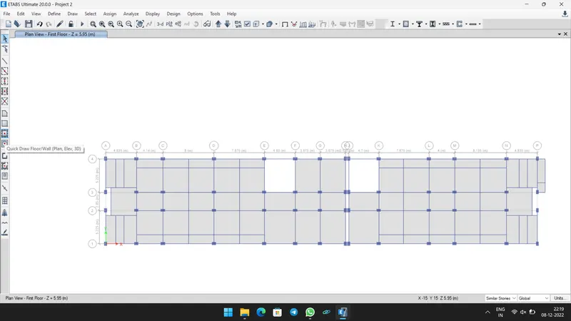
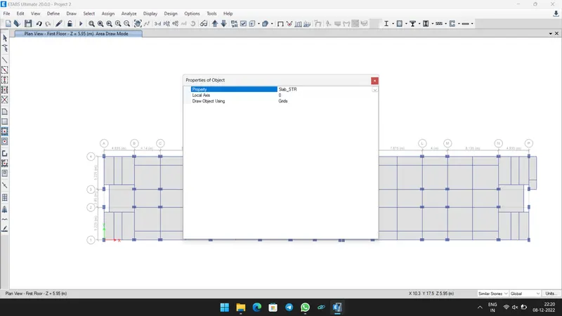
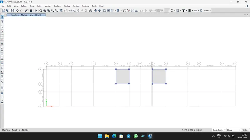
Step 5:-
- Select all Beams, and go to Assign Tab, select Distributed load in Frame Loads.
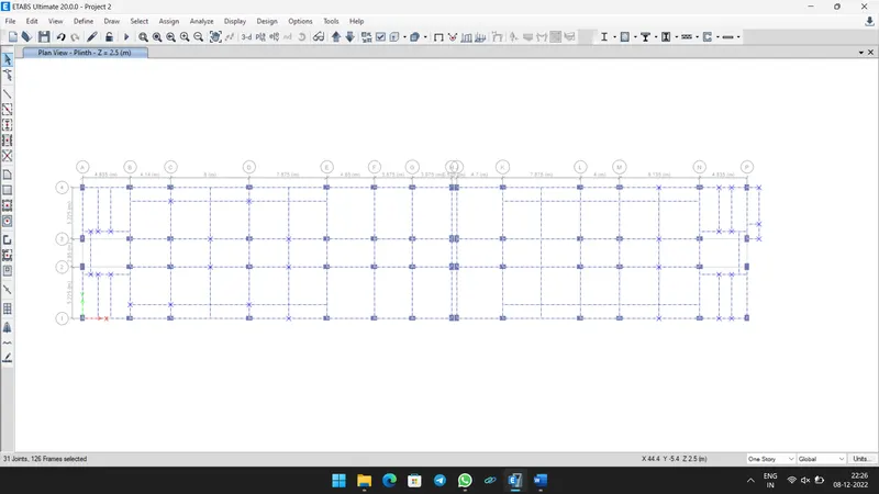
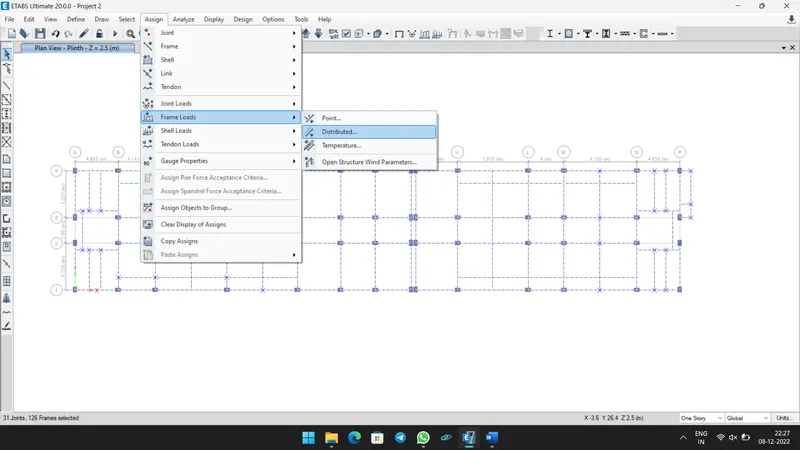
- A New pop-up window appears, Select Brickwall Load and give value as 3.5kN/m.
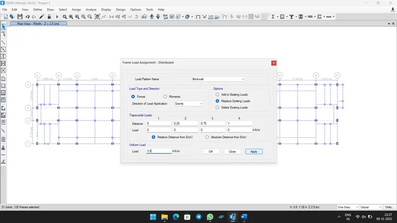
- Similarly, assign Brickwall load to Balcony wall of 1 kN/m.
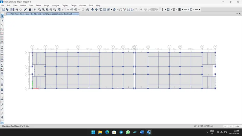
- Then select slab and Assign Floor Finish load (1 kN/m2) and Live load (2 kN/m2).
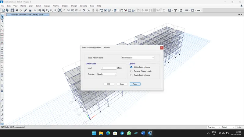
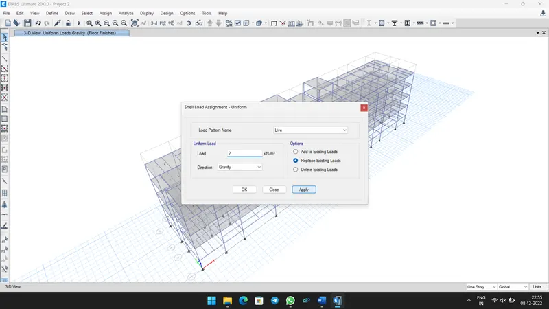
- Now Select all Slabs from Select Tab as shown below. Select Floor Option.
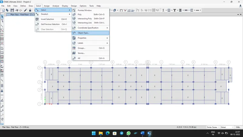
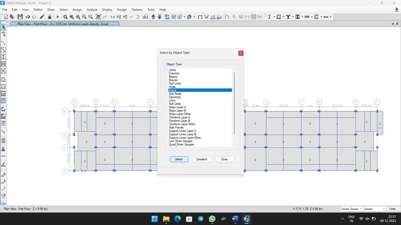
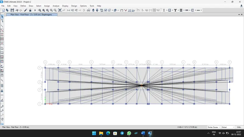
- Now to we have to Assign Diaphragms.
- To that first go to Assign Tab, select Diaphragms in Shell option.
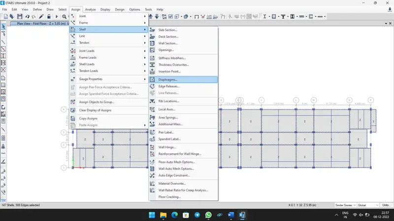
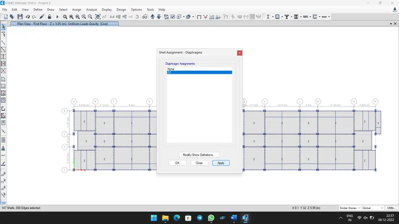
- Then select D1. Click OK.
Step 6:-
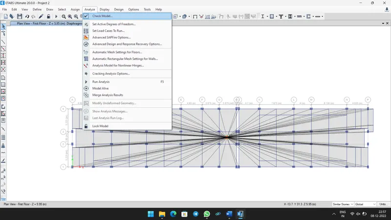
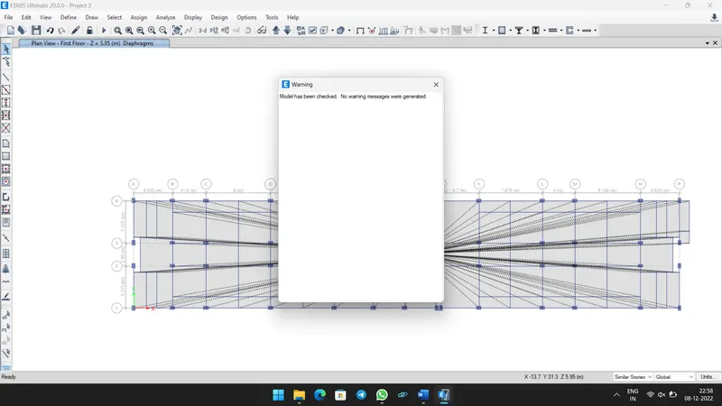
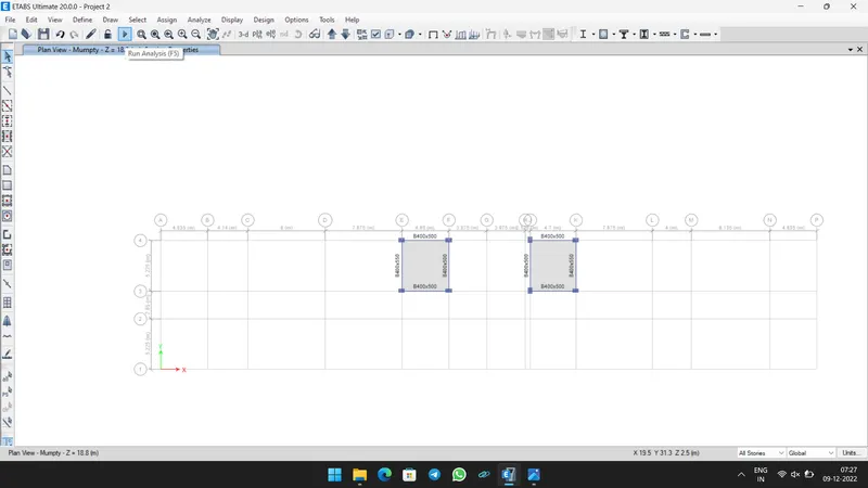
- To Run Analysis first we have to Check Model as shown below.
- It has to show No Warnings.
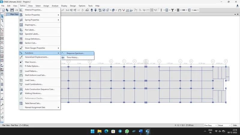
- Add Response spectrum from Define Tab.
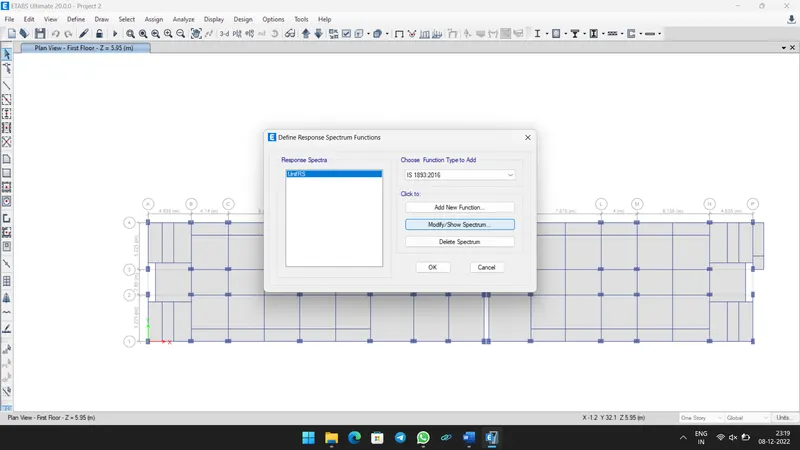
- Define Response spectrum as IS 1893:2016.
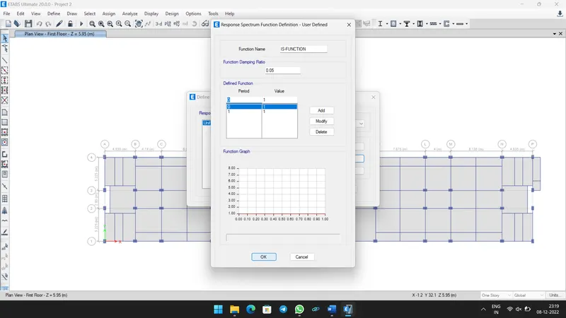
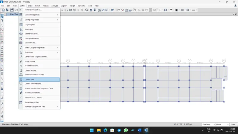
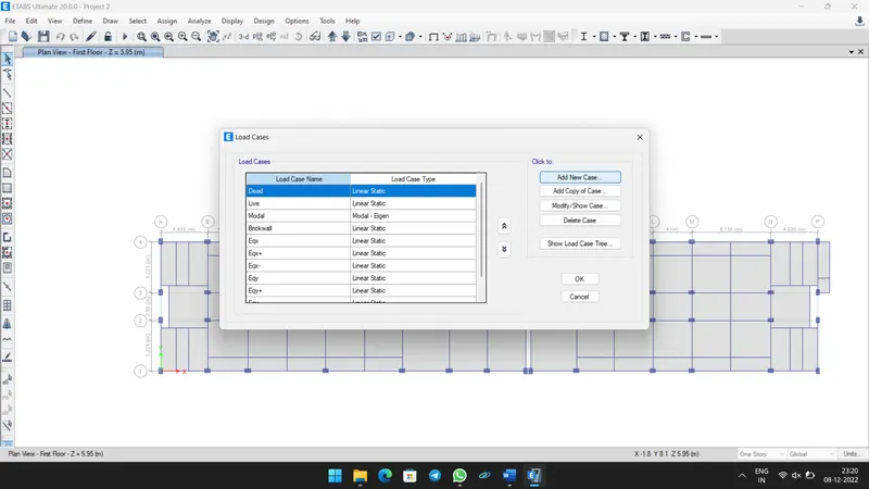
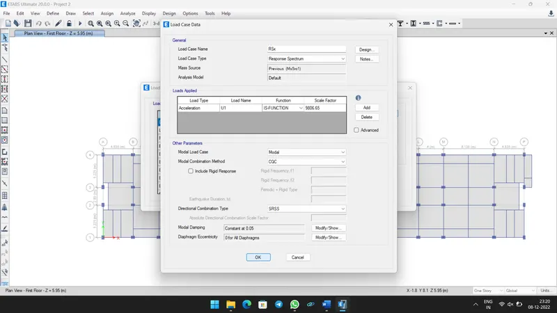
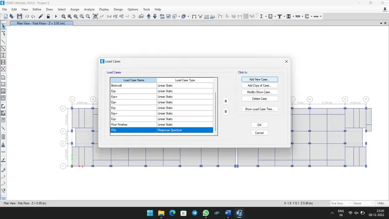
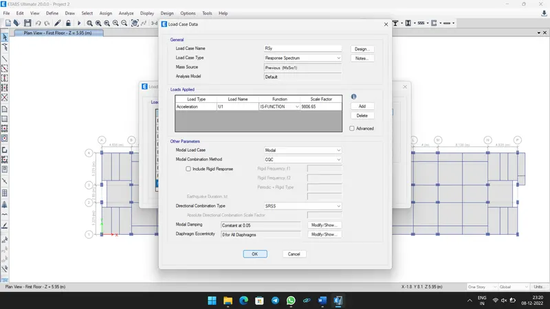
- Now go to Load Cases and define RSx and RSy Response spectrum loads as shown below.
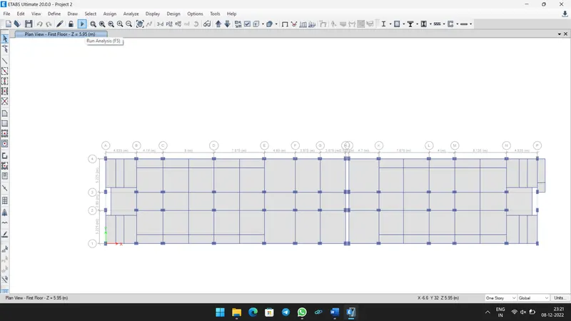
- Now Click Run Analysis.
Step 7:-
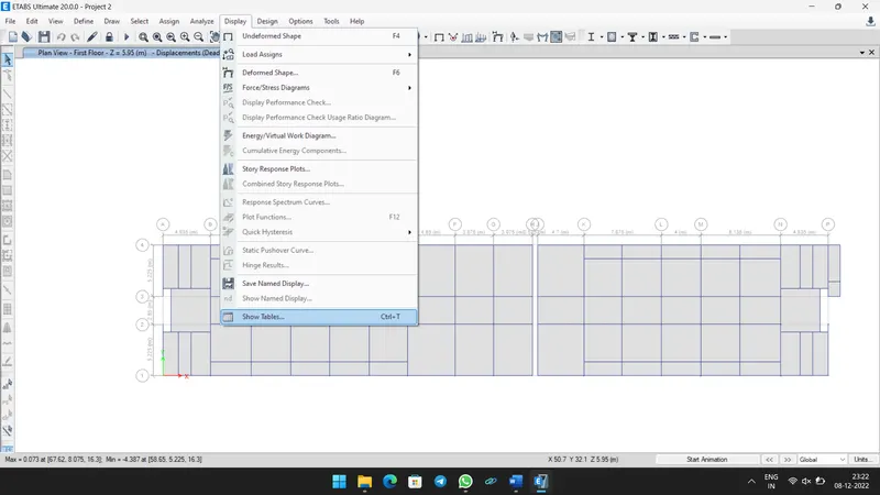
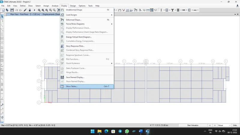
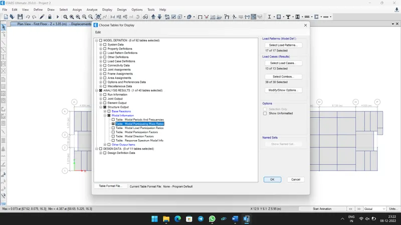
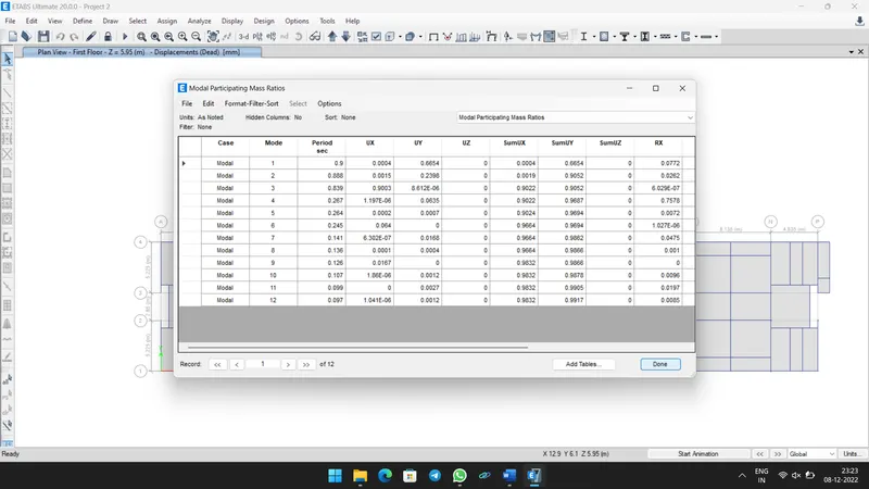
- Now Select Show Table Display Tab. To see the Modal Periods.
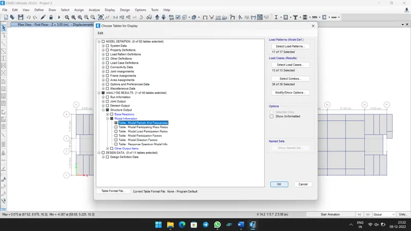
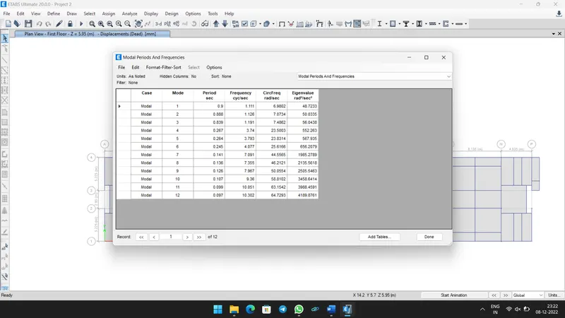
- The Sum First Three modes is greater than 65%. Hence the model safe.
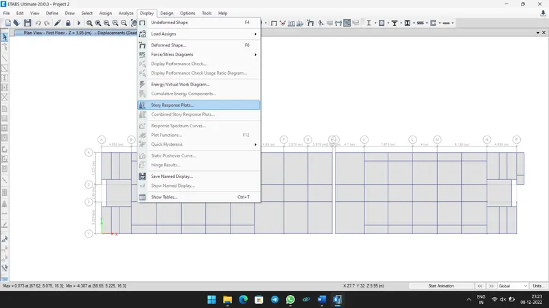
- Then select Story Response Plots, and see Story drift with Earthquake load.
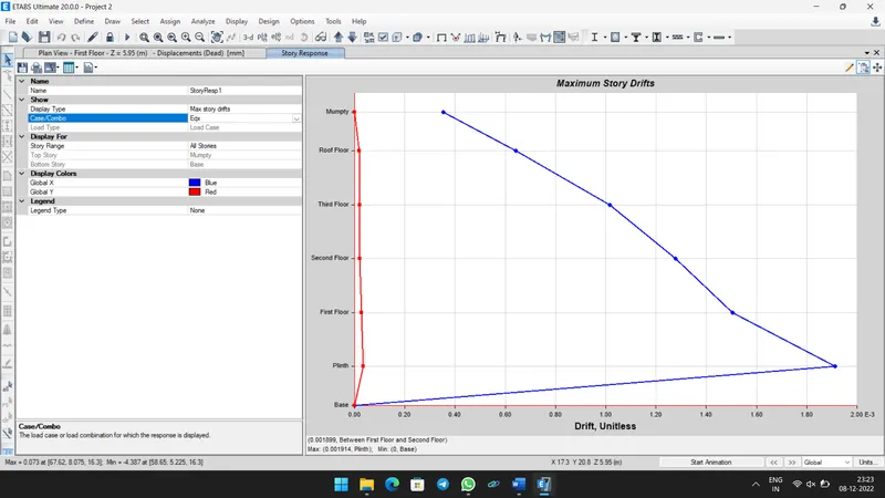
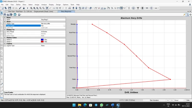
- Both X and Y Direction Story Drift value is lesser than 0.004. Hence safe.
Step 8:-
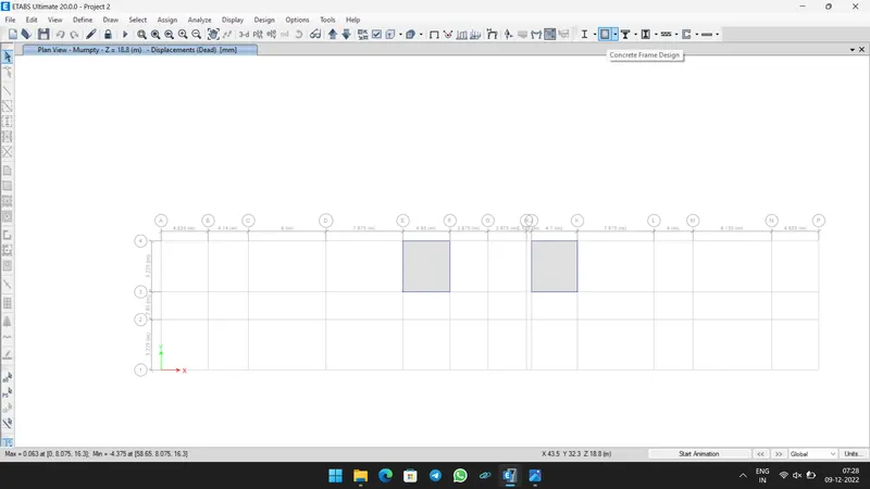
- Now Select Start Design/ Check in Concrete design tool.
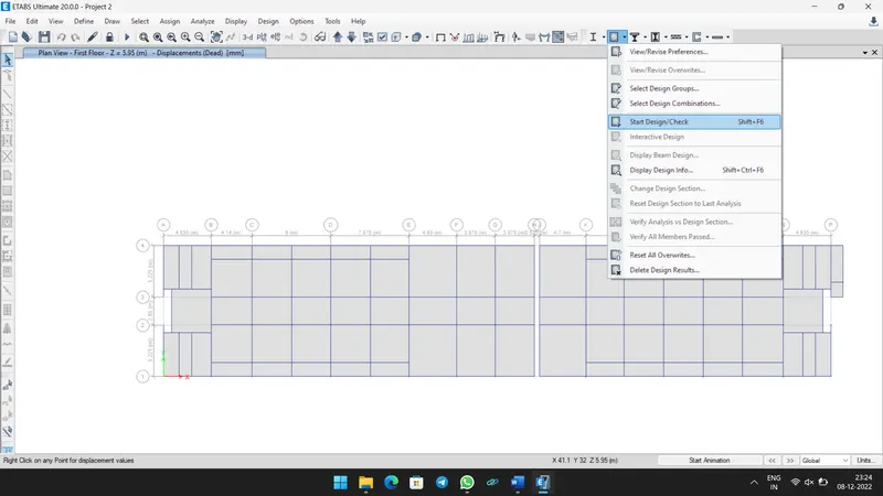
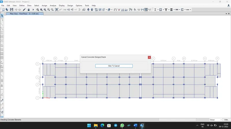
- It indicates some beams are red in colour it shows those beam are failed.
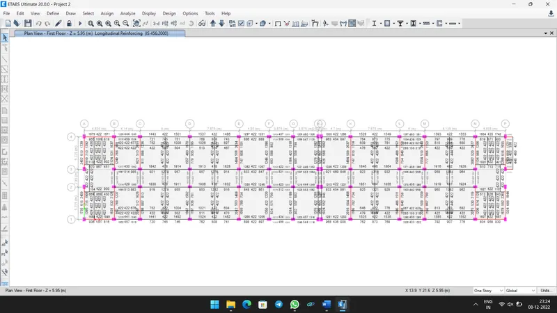
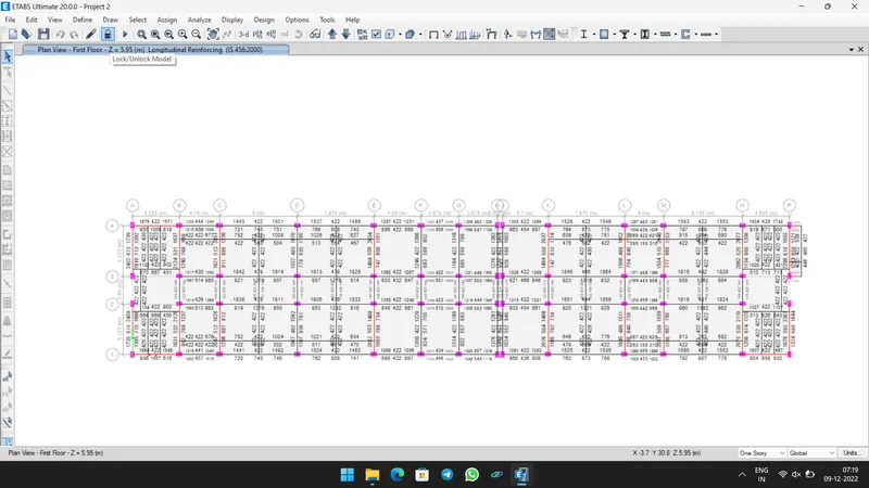
- To change the beam section properties, first we need to unlock the model
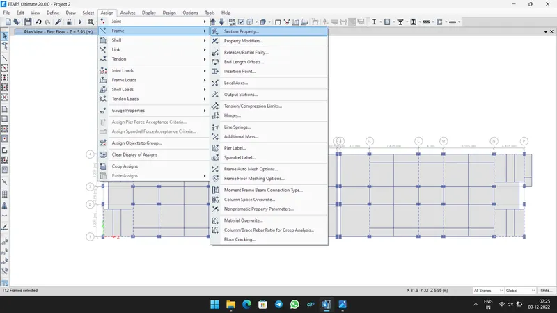
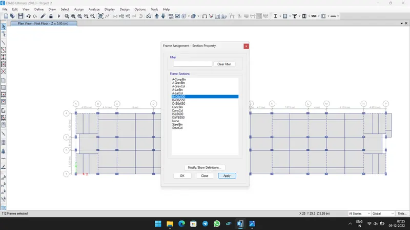
- And then add New Beam Section and assign the beams.
- Then again Run analysis and check the design.
- Repeat the same process until the beam gets passes.
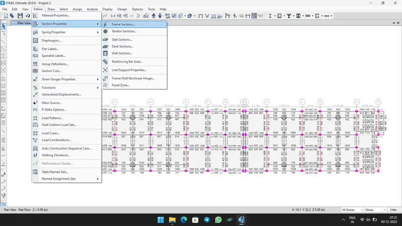
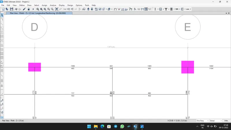
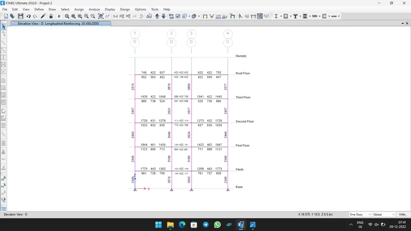
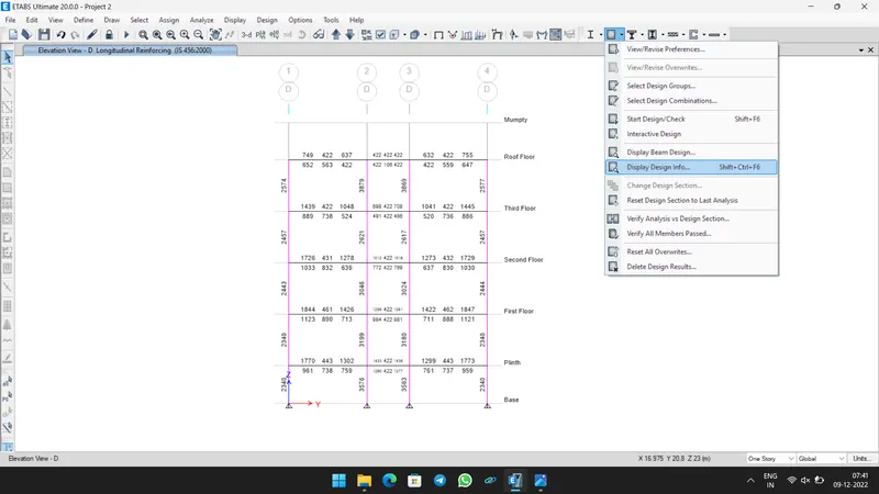
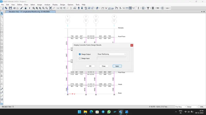
- To see the shear reinforcement requiremet, select Display Design info.
- And select Shear reinforcement.
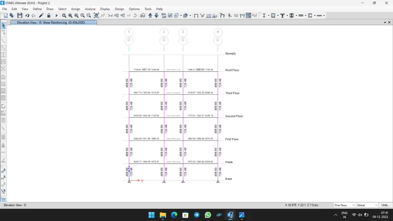
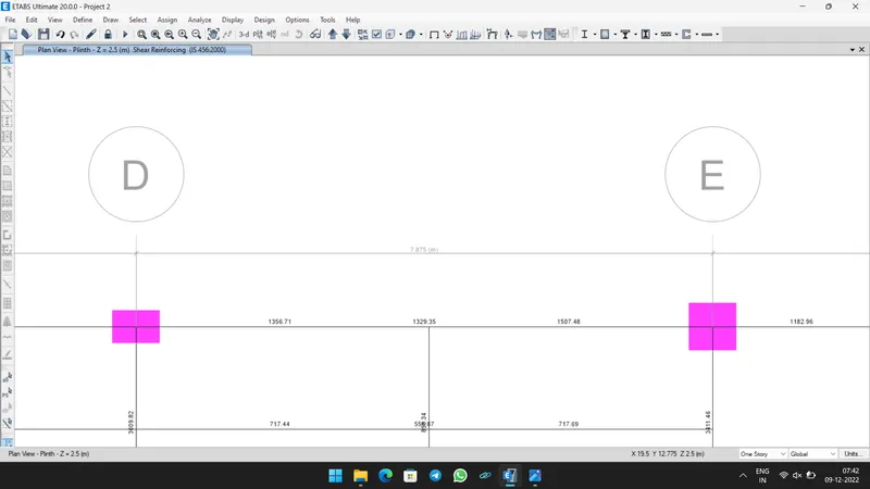
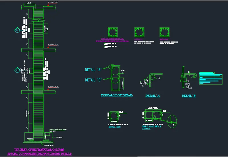
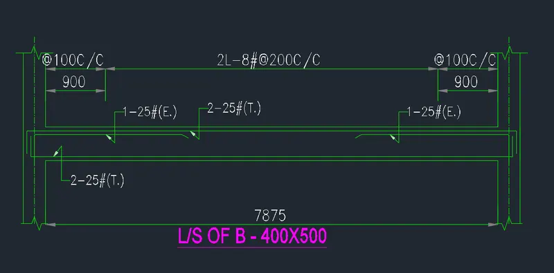
- Provide reinforcement details for beam D4-E4 and Column D4.
Foundation Design:
Given Data:
1) Location – Guwahati, Assam. It is Located in the Seismic Zone V.
2) Hostel block in an academic institute
3) Pile Length - 10m
4) Pile Diameter - 500mm
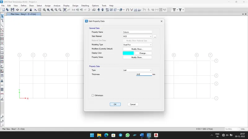
5) Pile Thickness - 800mm
6) Load Carrying Capacity of each pile - 280kN
7) Concrete - M25 Grade
8) Longitudinal Reinforcement - Fe500
Lets Assume,
- Center to Center distance betwwe the Pile to be 2.5 times the pile diameter - 1250mm
- Edge distance from pile to be 1 time the pile diameter - 500mm
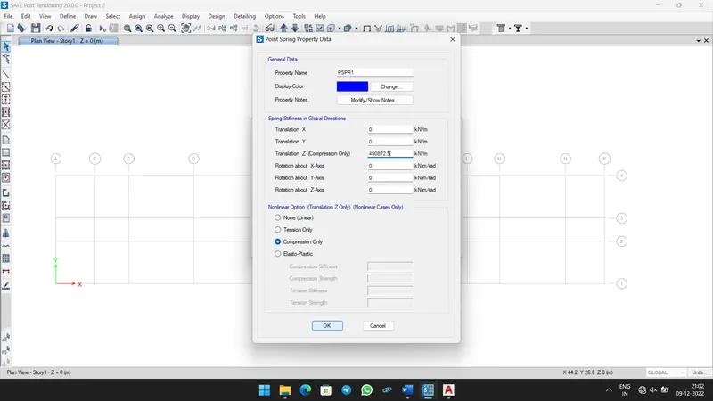
Point Spring Modulus (k) = AE/L
= 196349 x 25000 / 10000
= 490872.5 N/mm
= 490872.5 kN/m
Procedure:-
Step 1:-
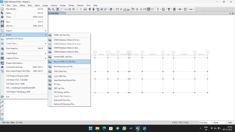
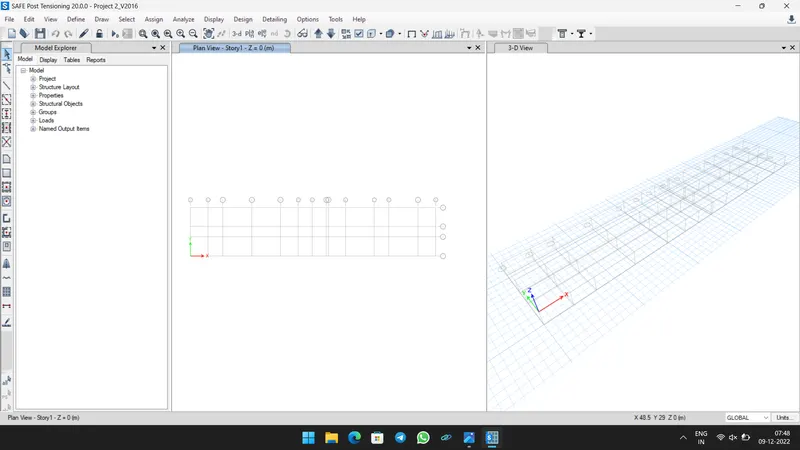
- In ETABS Software, Select Export option under File tab and click Story as SAFE File.
- A Pop-up window opens then click Base story and select all load cases and load combinations.
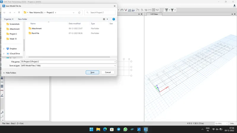
- And save the file in appropriate loaction and name.
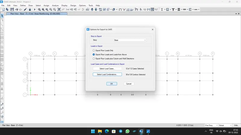
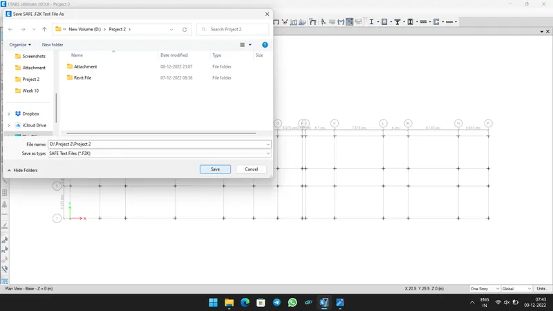
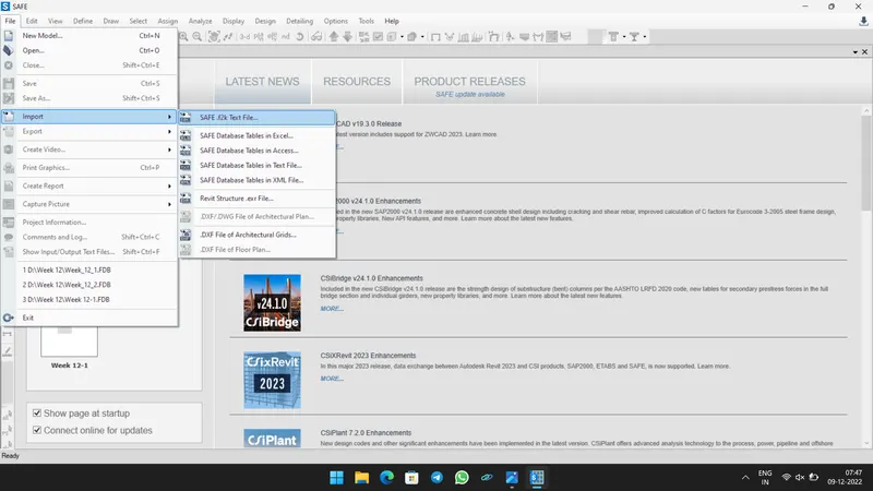
- Now Open SAFE Software, Select Import Option and click SAFE Text File.
- Then select the file and open.
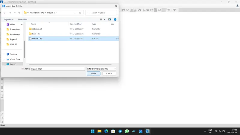
- Now the Grids, load cases and Load combinations imported from the model created in ETABS.
- Then Save the model.
Step 2:-
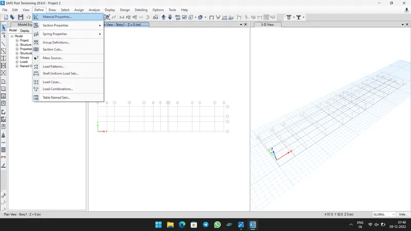
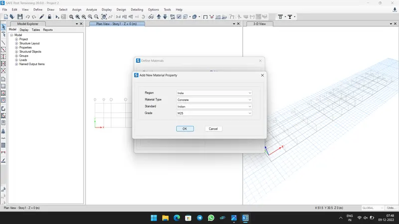
- In Define Tab, Select Material Properties.
- A pop-up window opens, in that click Add New Material.
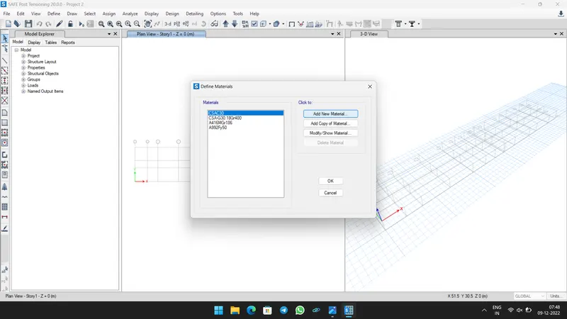
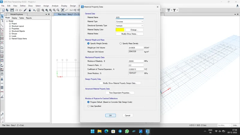
- Add Concrete material of Grade M25.
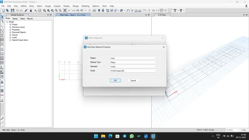
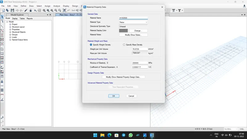
- Similarly add Rebar Fe500.
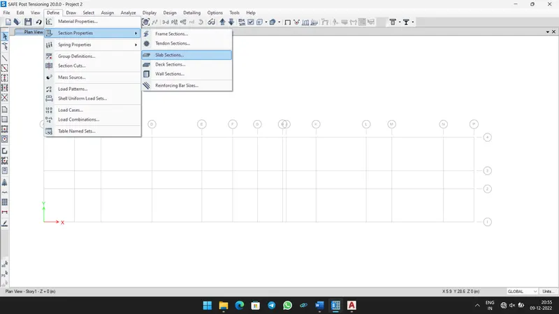
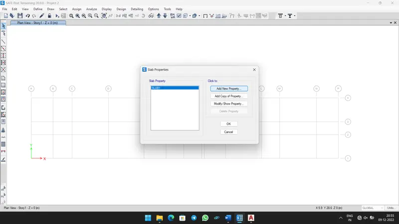
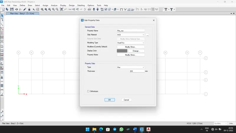
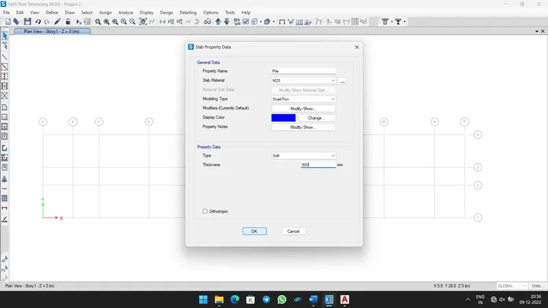
- Now define Slab Sections for Pile Cap as Mat Type, Pile as Stiff Type and Column as Stiff.
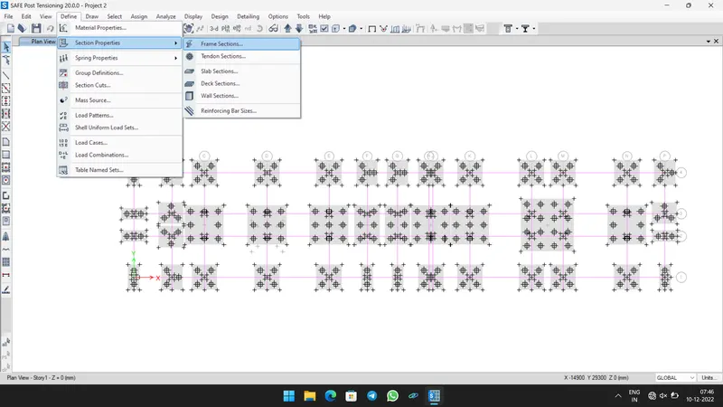
- In Define Tab, select Frame sections in Section properties.
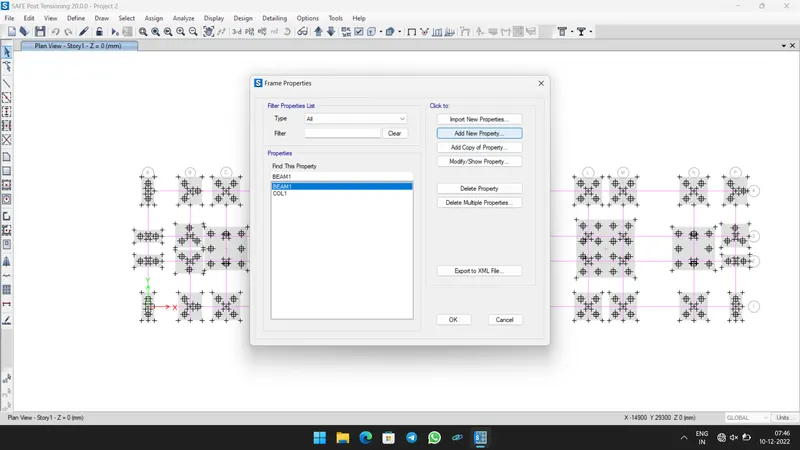
- Then Add new property and select Rectangular section.
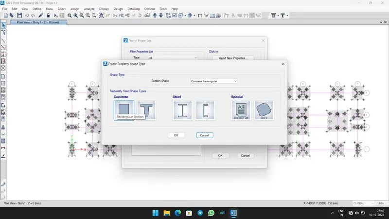
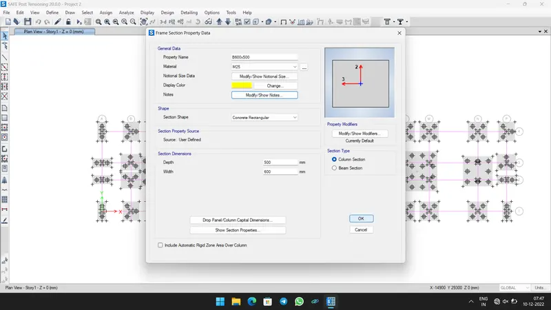
- Now define Tie Beam B600x400.
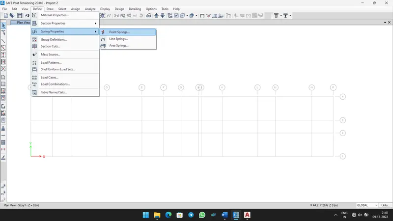
- Now Define Point Spring from Spring Properties under Define tab.
- Then click Modify/Show Property.
- Now give Z as 490872.5 kN/m and select Compression only.

Step 3:-
- First draw reference points to Draw the slab sections.
- Then Select Draw Rectangular Floor/Wall in draw tools.
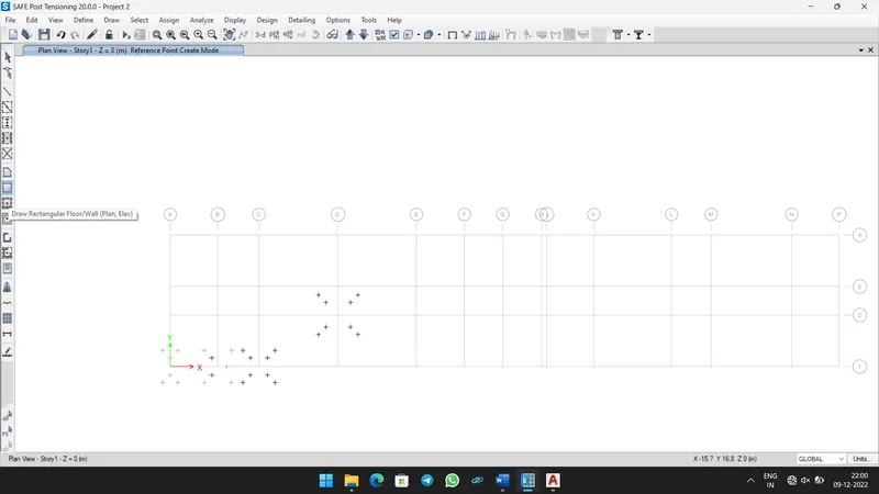
- Then select Pile Cap Slab and draw Pile cap as shown below.
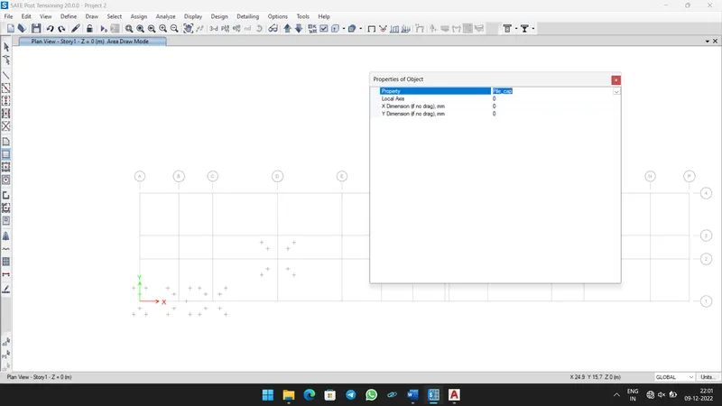
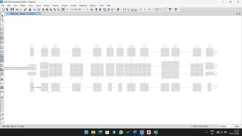
- Now select Quickdraw Area Around Point to Place Pile.
- And select Circular and diameter as 500mm.
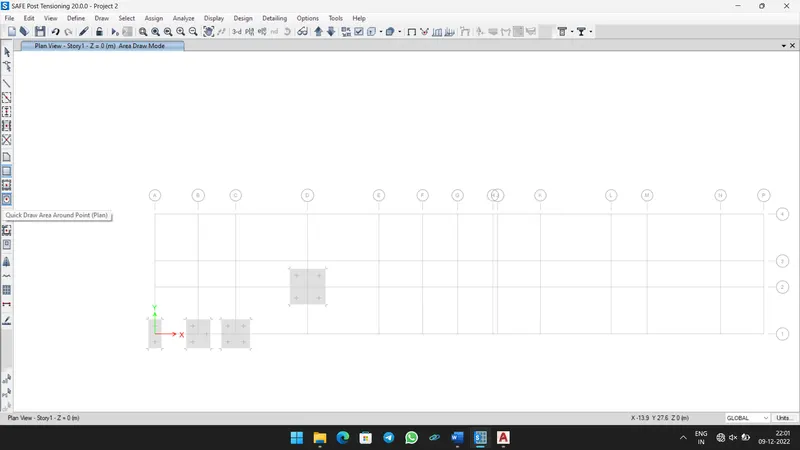
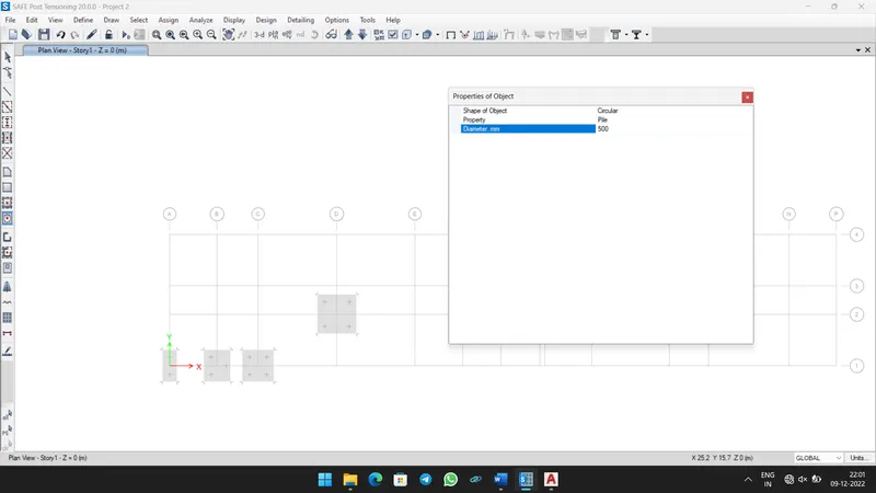
- Pile cap and Pile drawn successfully.
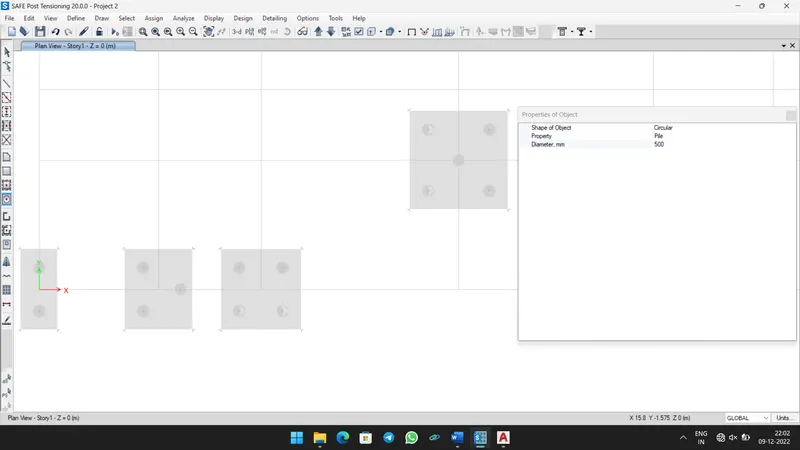
- Similarly draw all Pile Cap and Piles.
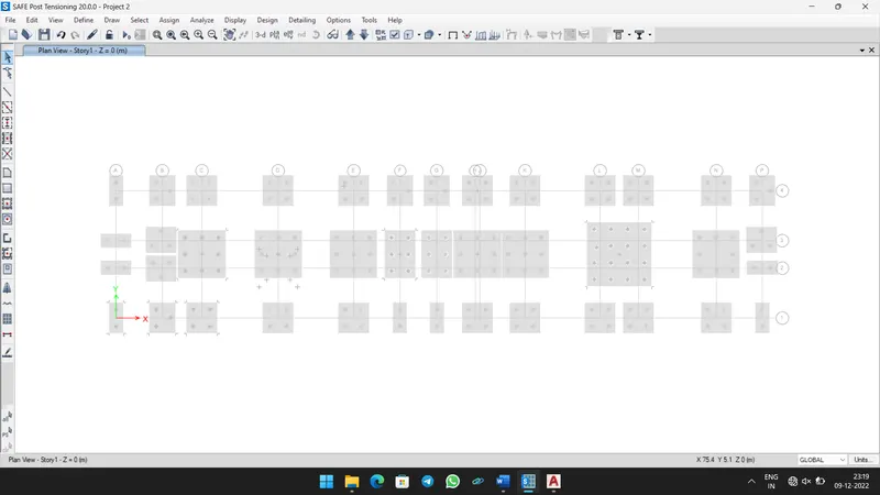
- Again select Quick Draw Area Around Points to draw the Column..
- And place all the column.
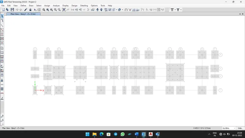
Step 4:-
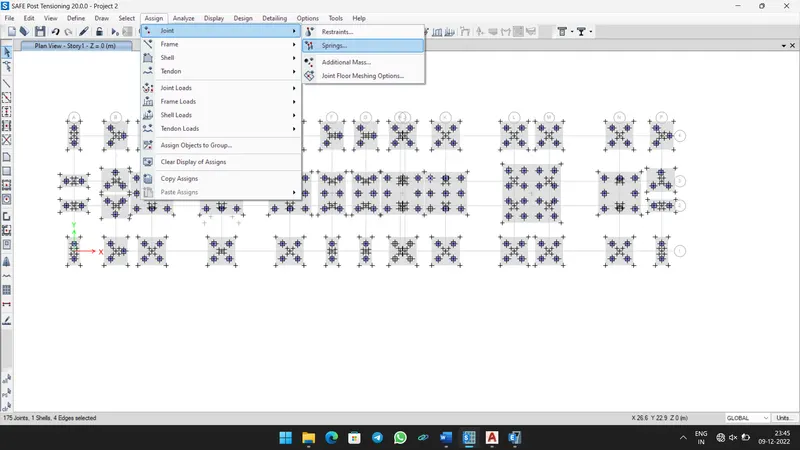
- Select center Joints of Plies.
- Select Springs in Joints under Assign tab.
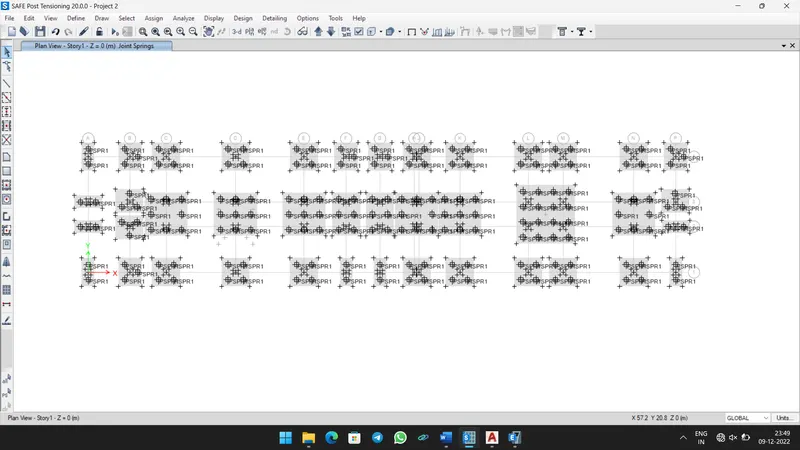
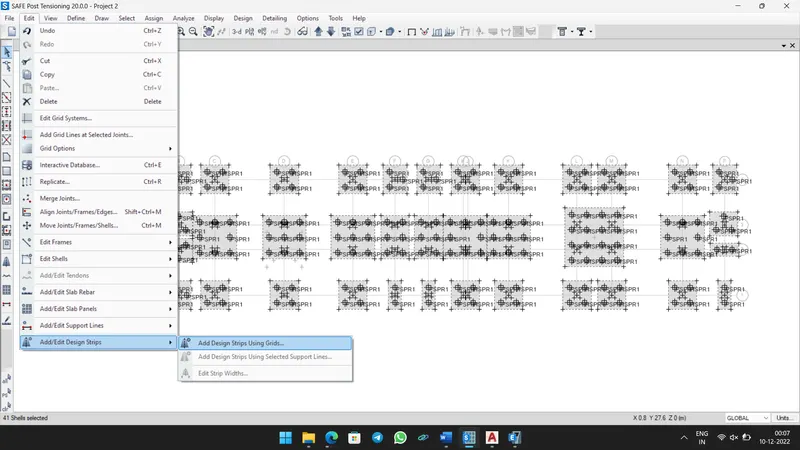
- Now go to Edit tab and select Add/Edit Design Strips.
- A new popup window opens, in that select Auto along A.
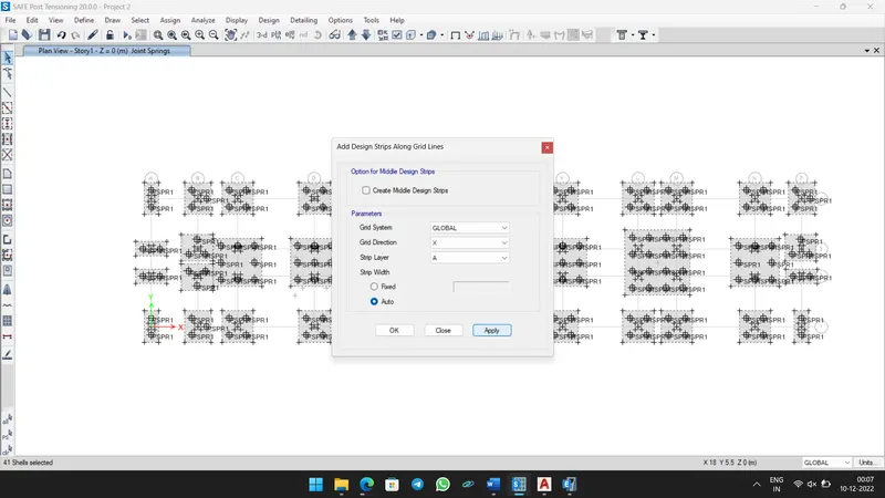
- Similarly Add Strip along B.
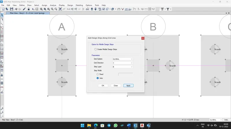
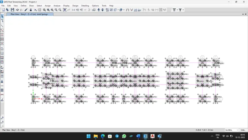
- Now draw the tie beam by clicking Quick Draw Beams/Columns.
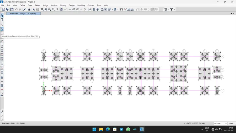
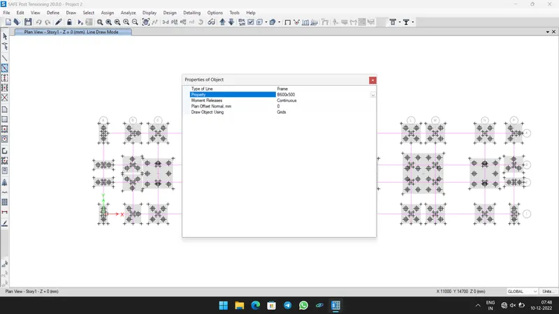
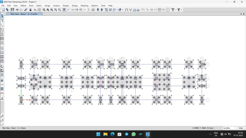
Step 5:-
- Now Click Run Analysis Icon.
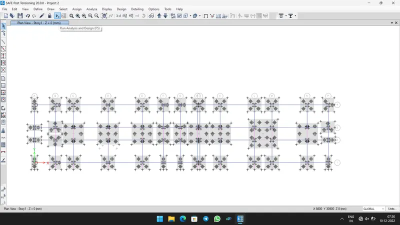
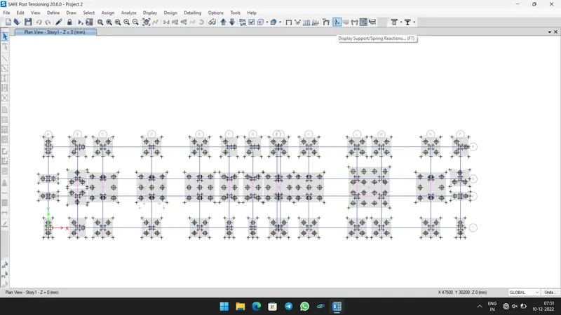
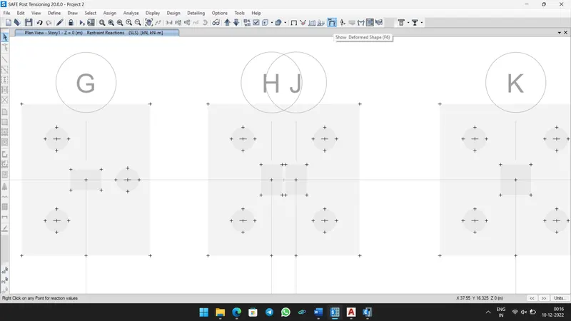
- Select Display Supports/Spring Reactions. Then select Service load combination.
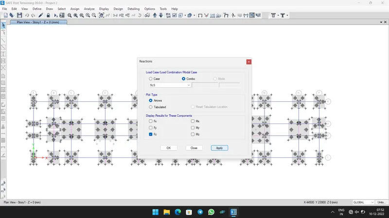
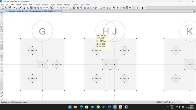
- Reactions are lesser than 280kN. Hence safe.
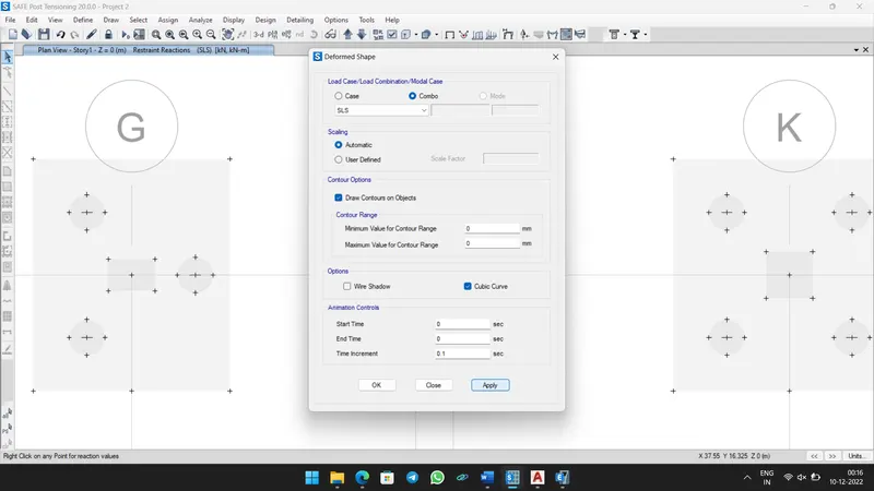
- Then select Show Deformed Shape icon.
- Select Service Load combination and see the displacement.
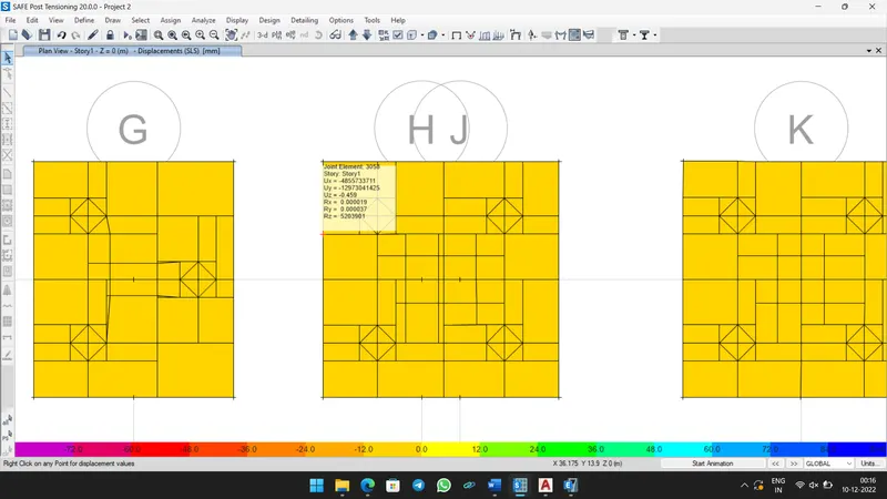
- Its Lesser than 25mm. Hence safe.
Step 6:-
- Then selectStart Design/Check in concrete Slab/Beam design.
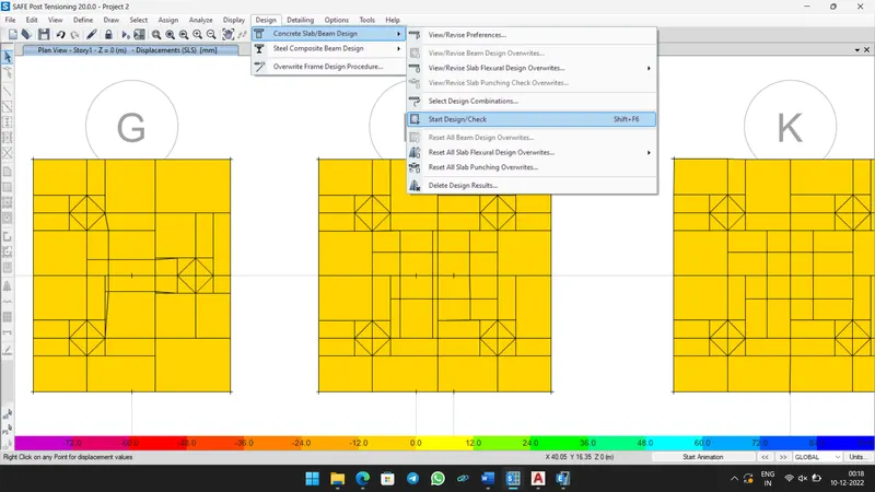
- Select Show Punching Shear Design in Display Tab.
- It shows lesser than 1. Hence safe.
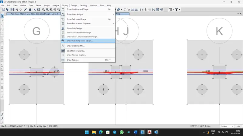
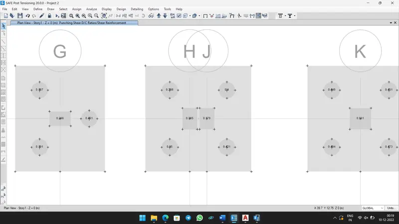
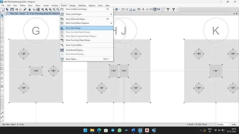
- Now select Show Slab Design in Display tab.
- Then Select Strip based. Check both the Strips A and B.
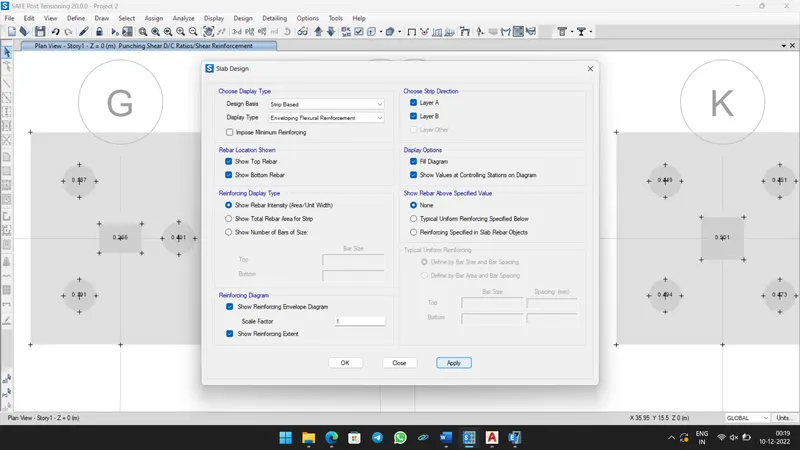
- Now the Reinforcement requirement details shows.
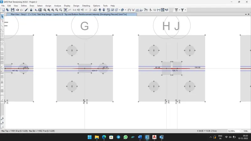
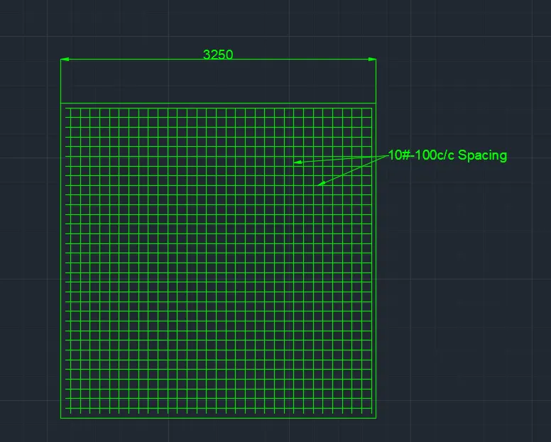
- Hence Provide 10mm dia bars at 100mm center to center spacing at bottom of HJ 4 Grid Pile Cap.
Result:-
- Modelling, Analysing and Design of RCC Building in ETABS Software was done successfully.
- Modelling, Analysing and Design of Pile Foundation using SAFE Software was done successfully.