Project 2_Design & Analysis of a Hostel building at Guwahati, Assam
Aim
To Plan, Analysis and Design the G+5 Storey hostel Block Located in Guwahati Assam using Etabs Software and to design Foundation for the building by using SAFE software.
Also to produce Structural Detailing of rebar’s to the plan.
Given Data
- G+3 Building
- Walls AAC Blocks
- Soil Type as Type 3, Pile of Length 10m and Diameter 500mm, Load Carrying Capacity of 280 KN
- Ground level is 2m Above existing level
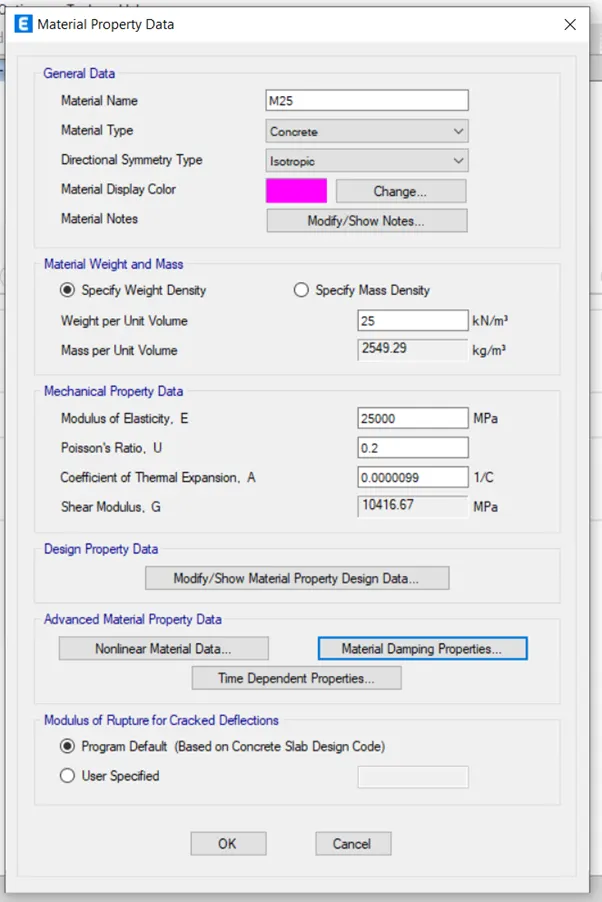
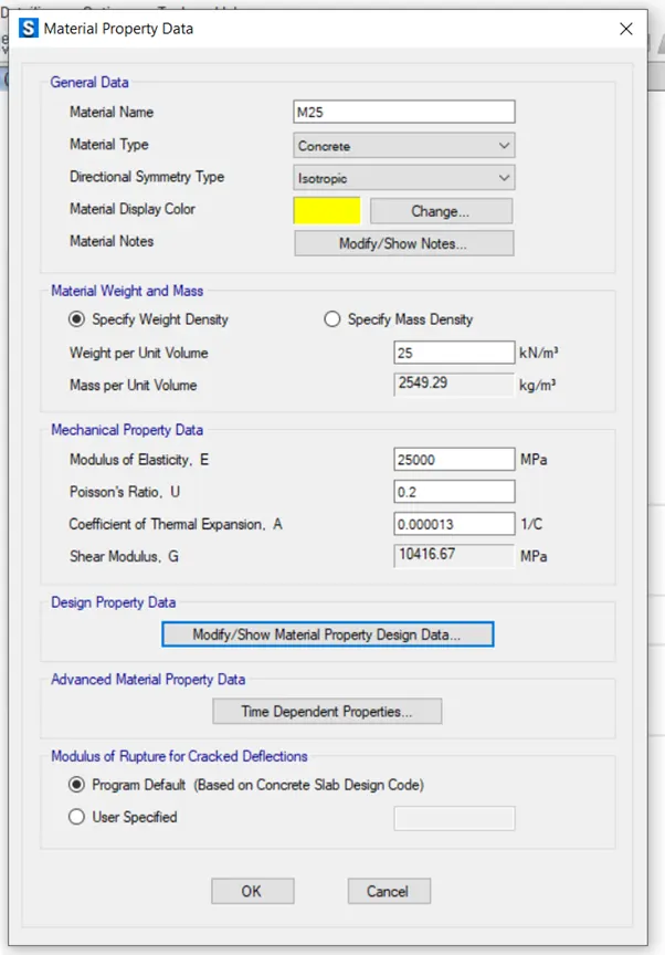
- Grade Of Concrete M25
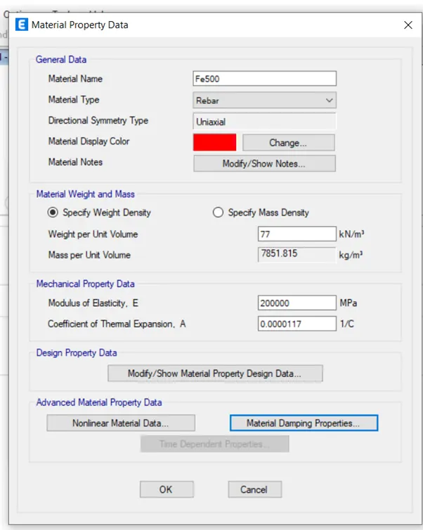
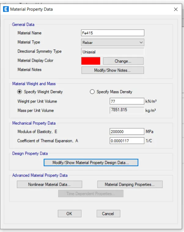
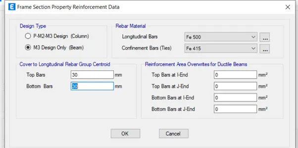
- Longitudinal Steel Fe500 and Shear Steel Fe415
Data Required for Etabs Analysis
- Support Condition as Pinned
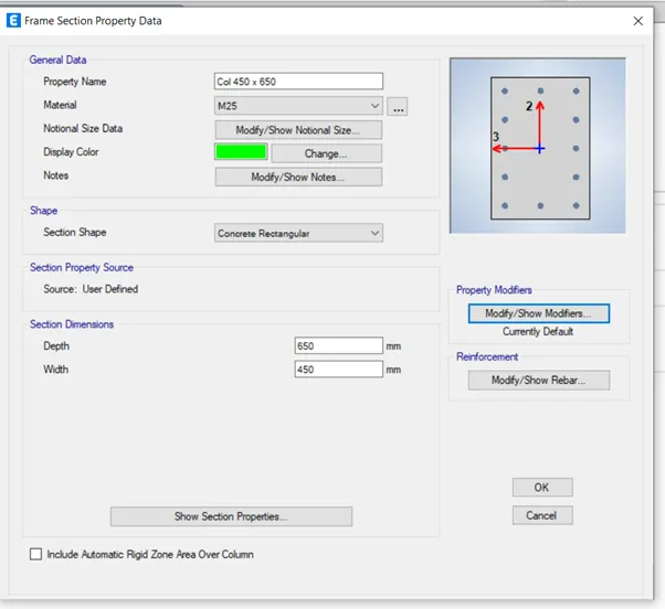
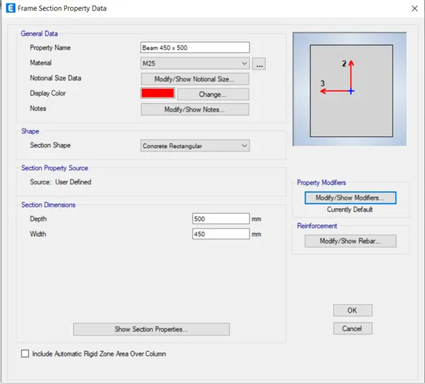
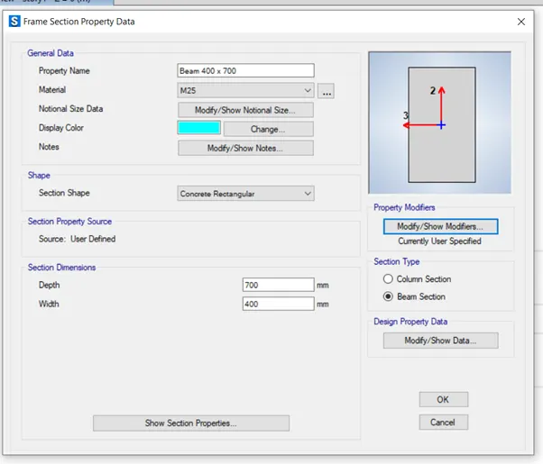
- Column Size as 450 x 650 and Beams as 450 x 500
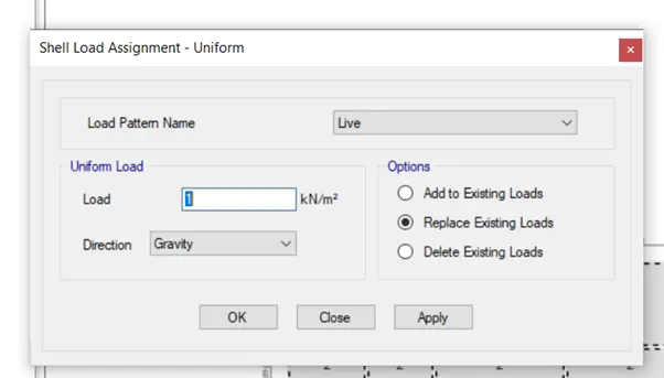
- Live Load as per IS 875 is 2KN/m2 for Residential and Commercial buildings
- Live load in Terrace is 1.5KN/m2
- Floor Finish as 1KN/m2
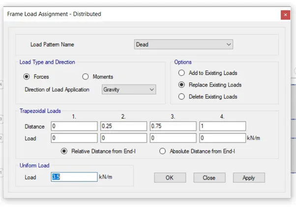
- Wall Load for AAC blocks 5KN/m
- Since the Building is in Guwahati it comes under Zone 5 as per IS 1893 2016
Procedure
- Open Etabs, Click New Model.
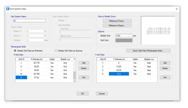
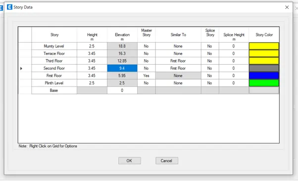
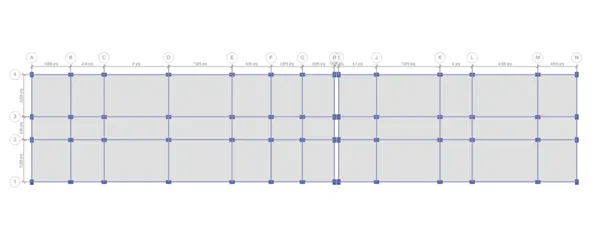
- Give Grid lines and Storey Height as per the drawings provided by the Architects.
- Then go to define frame properties and add new property.
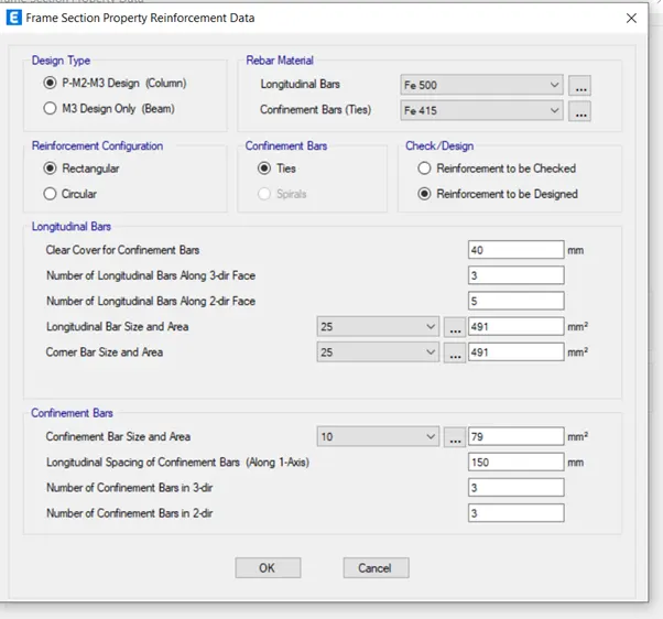
- Give Grade of Concrete as M25 and then Longitudinal Steel as Fe 500 and Shear steel as Fe415.
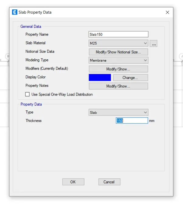
- Then go to define and Section Properties. New and rectangular section give properties for beams, columns and slab.
- Give reinforcement details for both and the stiffness modifier for beams is 0.3 in Moment of Inertia x and y direction.
- For columns stiffness modifier is 0.7 in both the directions.
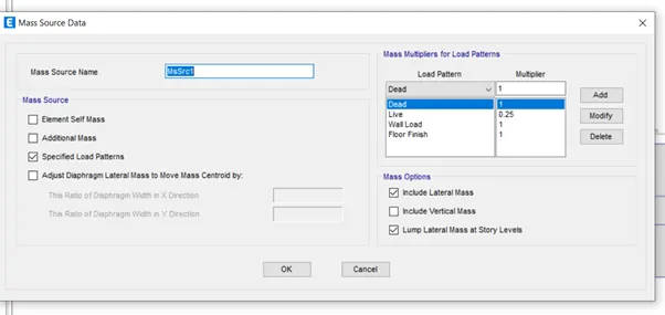
- Then give mass source.
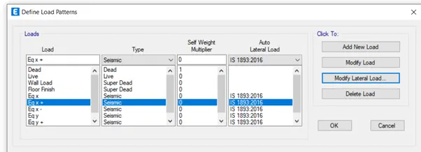
- Define load Patterns and load cases with live load as 0.25.
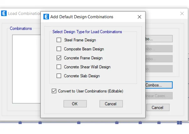
- Then create load combinations.
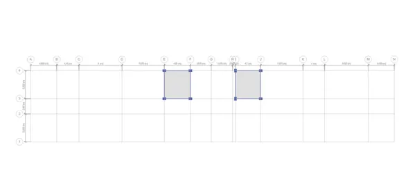
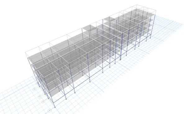
- Then create columns by quick draw columns and beams by quick draw beams and slabs by draw slabs or wall panels for all the floors.
- Delete the structural elements where ever not required.
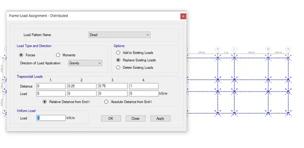
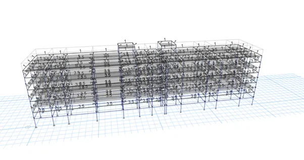
- Then assign loads by selecting all the beams and assign frame load wall load as 5KN/m2
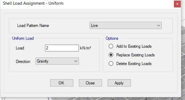
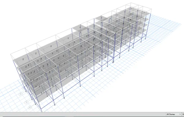
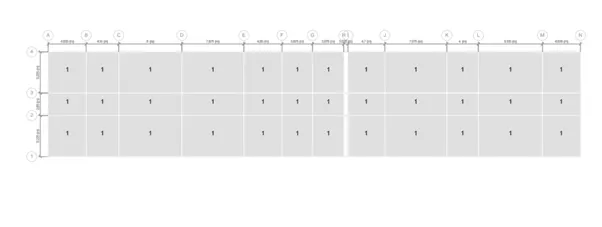
- Then select all slabs and assign shell load, live load of 2Kn/m2 and floor finish as 1KN/m2
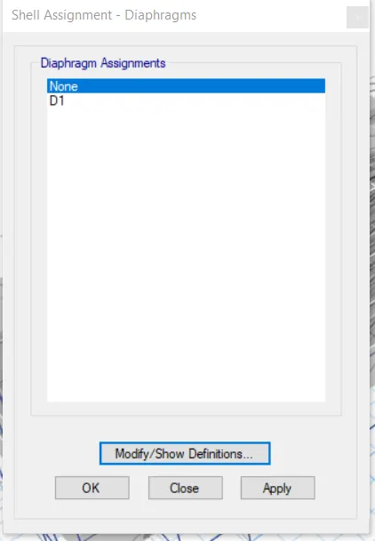
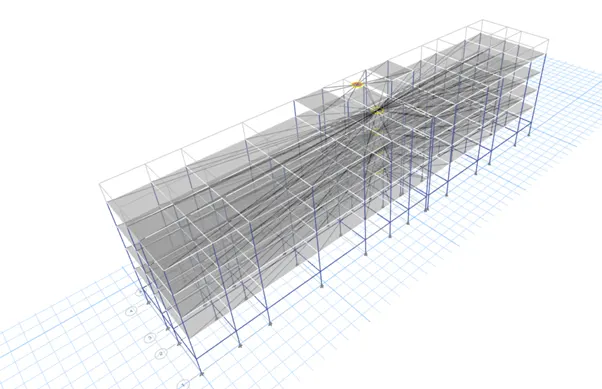
- The assign diaphragm for all the slabs.
- Check the model and run analysis.
- Once completed the run design
- Then take the longitudinal steel for beams and columns. Then by using the values give the required steel.
Input
Load Pattern
Dead Load – Dead - 1
Live Load – Live – 0
Wall Load – Super Dead - 0
Floor Finish – Super Dead – 0
Earthquake Load in both x and y Directions. As per IS 1893 2016
Time period T = 0.009 x h / Sqroot d
For x direction T = 0.017
For y Direction T =0.040
Response Reduction factor R = 3
Importance Factor = 1.5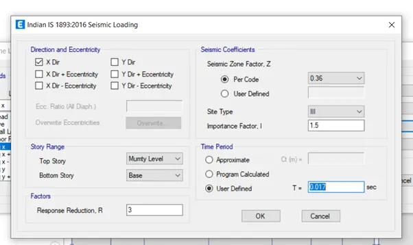
Output & Result
Run the Analysis and Design. Then take the Result
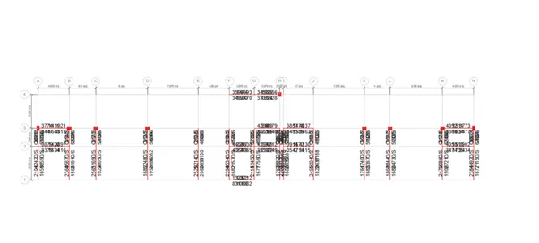
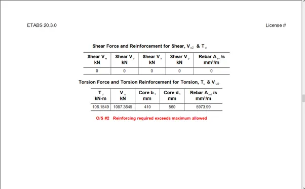
In our building the selected columns and beams are failing due to reinforcement required exceeds maximum allowed.
Unlock the analysis and Check the beam joints are connected with the column joints, connect all the beams and columns properly and then re-run the analysis.
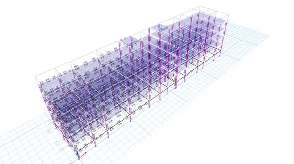
All the beams and columns are passing. We will design the reinforcements for beams and columns.
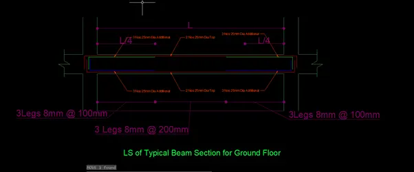
Typical Reinforcement details for Ground Floor Beams
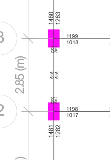
Typical Column Reinforcement for E 2 Grid
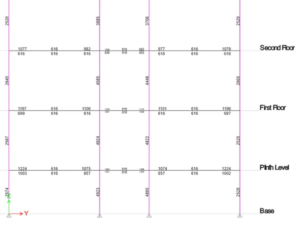
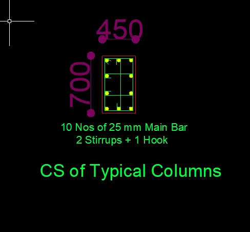
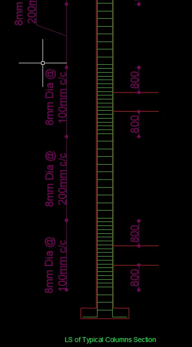
Similarly, the reinforcement details are calculated for all the stories.
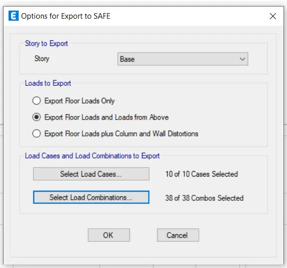
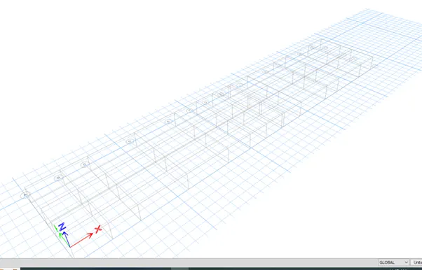
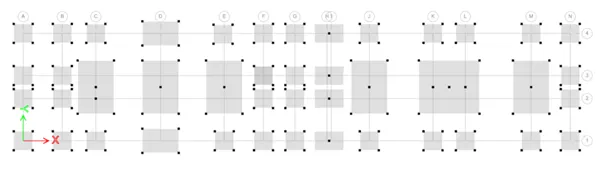
Now we export the file to safe for foundation design.
Given Data
Pile Diameter = 500mm
Load Carrying Capacity = 280 KN
Length of Pile = 10m
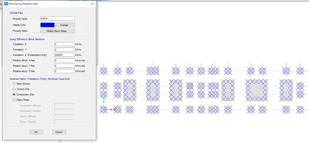
Spring Constant = EA/L
E= 25000N/mm2
Area of pile = (500 x500 x 3.14) / 4
= 196250 mm2
Spring Constant = (25000 x 196250) / 10000
= 490625 N/mm or 490625 KN/m
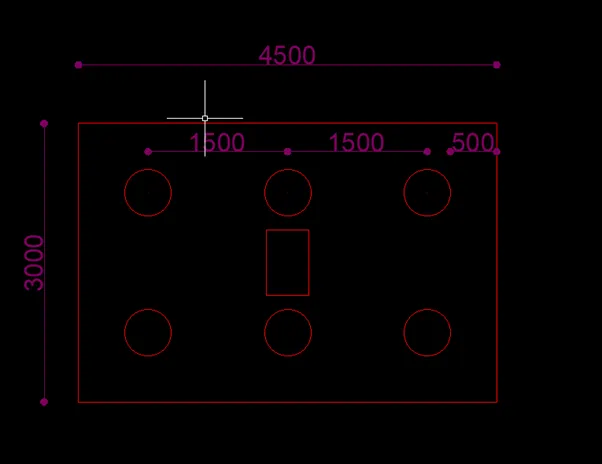
Distance Between Pile = 3 times dia of Pile
= 1500mm
Distance from pile cap to edge = 500mm
Lets assume Depth of Pile = 700mm
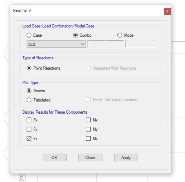
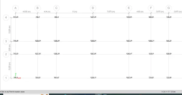
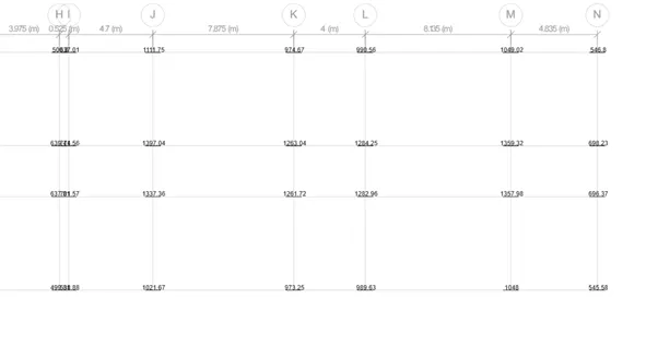
For Axial Loads in the Columns I have created a Serviceability Load Combination of Dead load, Live Load, Wall Load and Floor Finish.
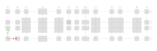
Pile Arrangement
For Load of up to 1110 KN I am using piles of 500mm Diameter
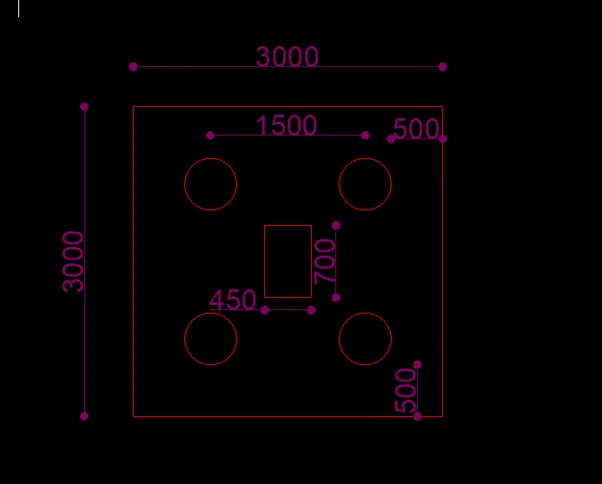
For Axial Load up to 1600 KN we use 6 No of Piles
Input
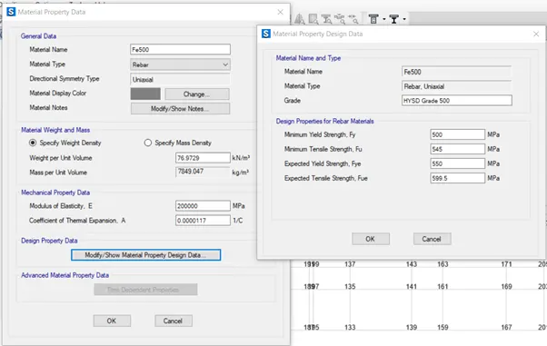
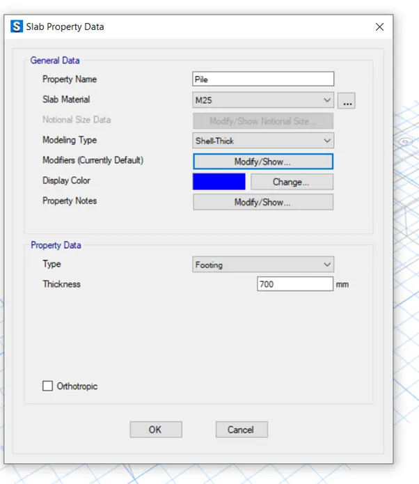
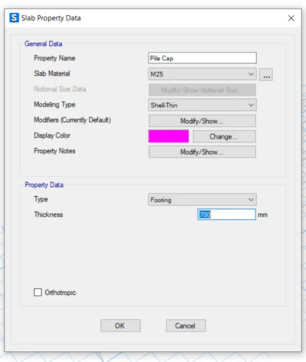
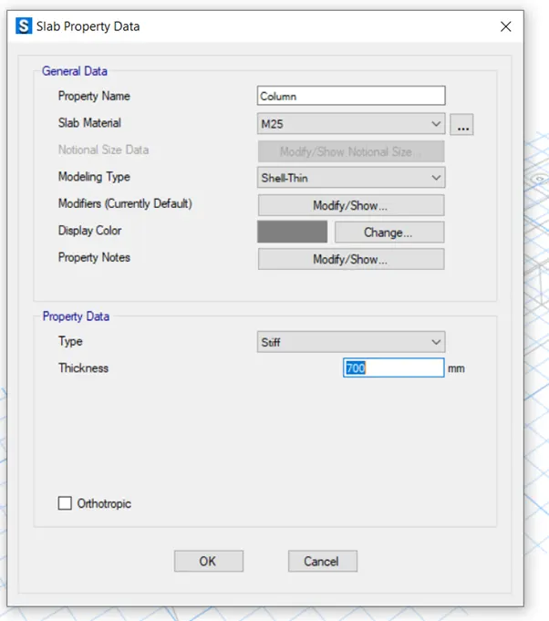
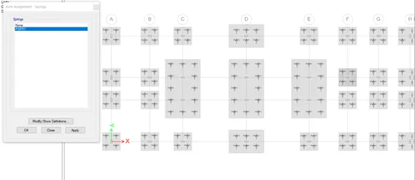
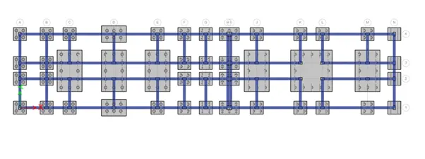
Output & Result
Run the Analysis and Design then get the result
Check for Deformed Shape
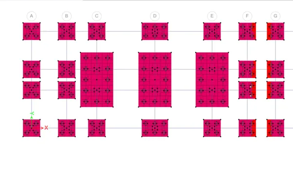
The values of Deformation are Less -0.3 the maximum allowed deformation is 50mm Hence Ok.
Check for Bearing Capacity
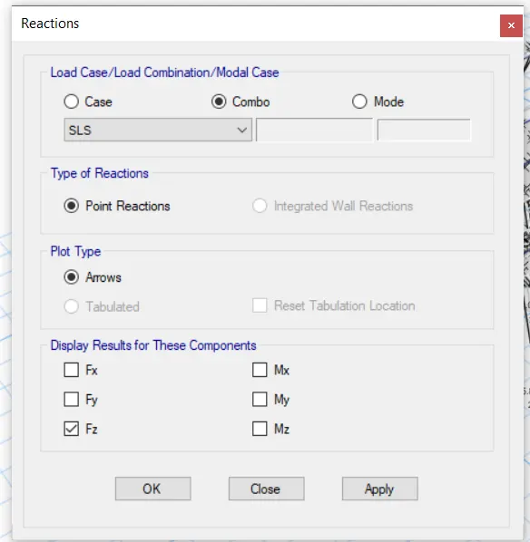
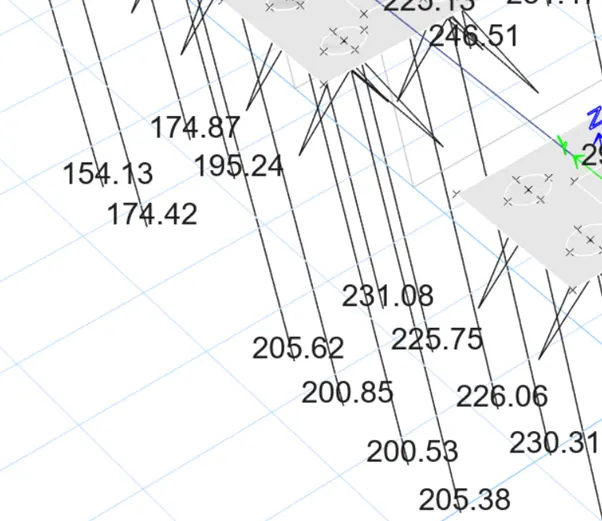
The maximum Allowed Bearing capacity of pile is 280 KN. We got less than that Hence Ok.
Check for Punching Shear
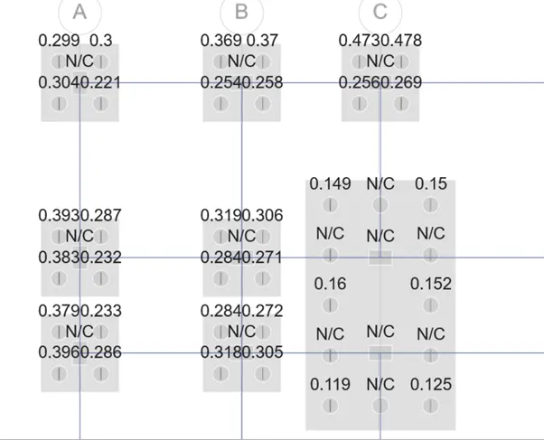
Punching Shear is Less than 1 Hence Ok.
Strip Assignment
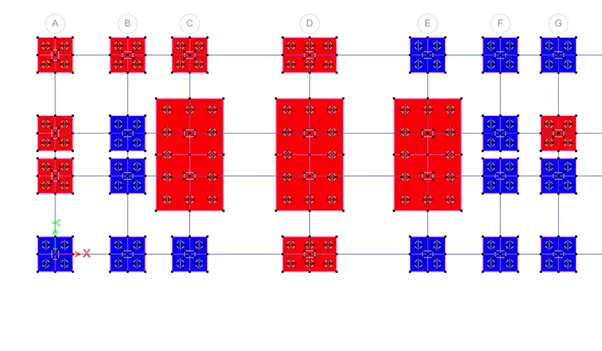
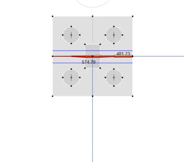
Maximum Bottom Reinforcement Is 574mm2/m
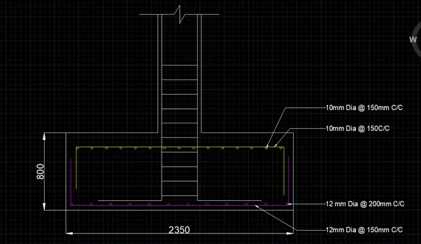
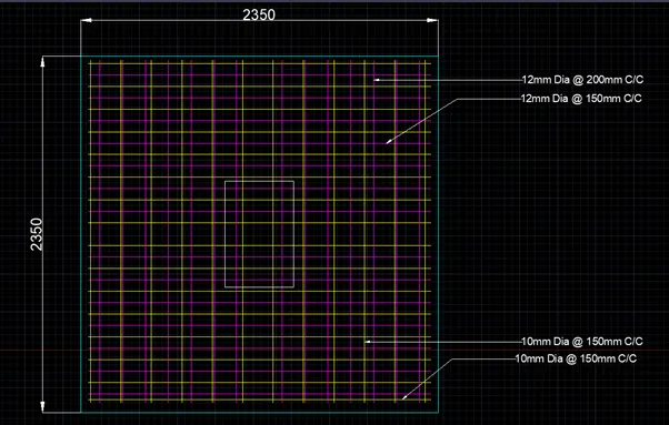
Hence Provide 12mm Dia at 150mm C/C @ Bottom in x Direction
Maximum Top Reinforcement is 482 mm2/m
Hence Provide 10mm Dia at 150mm C/C at Top in X direction
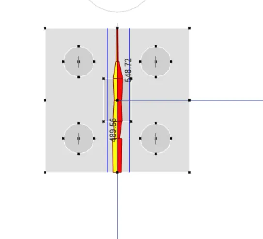
The maximum Bottom Reinforcement 549 mm2/m
Hence Provide 12mm Dia at 200mm C/C at Bottom in Y direction.
The maximum Top Reinforcement is 489.56
Hence Provide 10mm Dia at 150mm C/C at Top in Y direction.