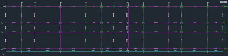
Project 2_Design & Analysis of a Hostel building at Guwahati, Assam
Project 2
AIM
To design and analyse for a G+3 Hostel block in Guwahati, Assam in ETABS and also foundation details using SAFE.
INTRODUCTION
ETABS is an engineering software product that caters to multi-story building analysis and design. Modeling tools and templates, code-based load prescriptions, analysis methods and solution techniques, all coordinate with the grid-like geometry unique to this class of structure.
SAFE offers a single user interface to perform modeling, analysis, design and reporting. A new model explorer is available for quick access to objects, properties and forms. It is ideal for modeling foundations, basemats, and footings. Easily model soil supports and zero tension soil models with uplift analysis. The area assignment of soil supports is based on the subgrade modulus, and they automatically adjust whenever the mesh changes. Basemat foundation models can include pedestals, walls, columns, beams, and piles in addition to the foundation area.
DETAILS AND CALCULATIONS
Details Required for ETABS Analysis
|
Details required for SAFE analysis & Design
|
PROCEDURE
1) ETABS
- Open ETABS Software
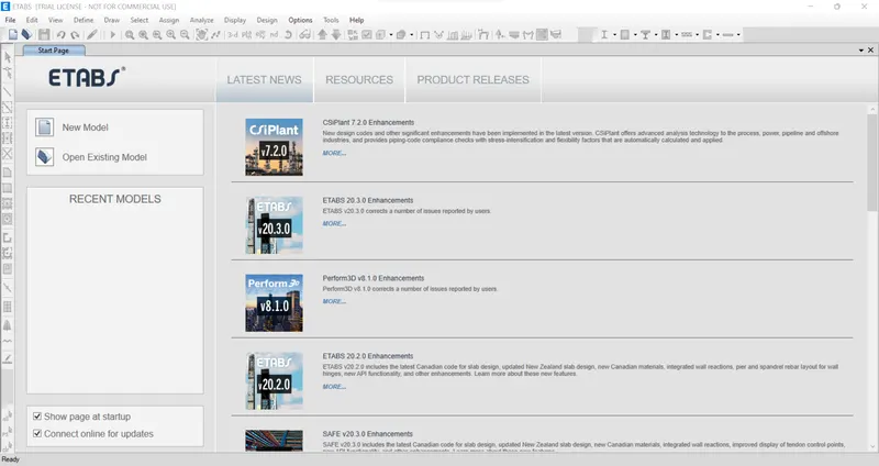
STEP 1: Model Initialization
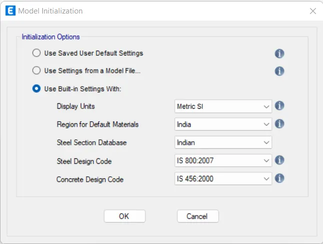
- Click 'New Model' and select 'Use Built-in Settings With:'
- Assign all options as given below
- Click 'OK'
STEP 2: Grid Spacing
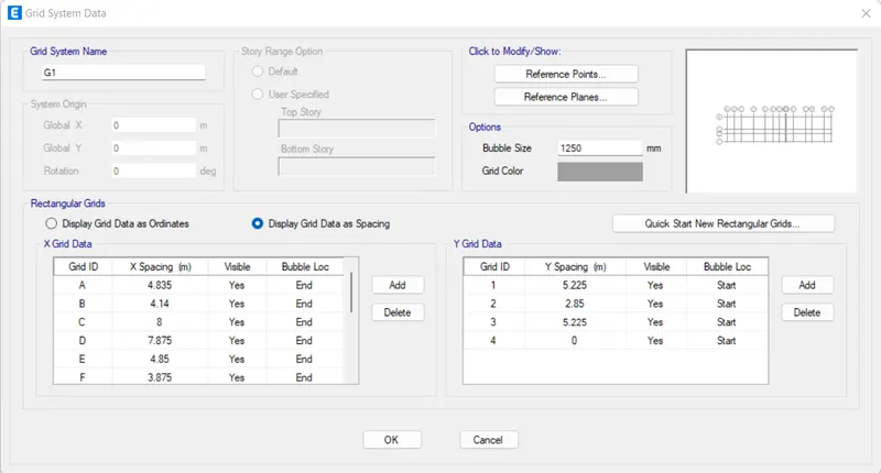
- Click 'Custom Grid Spacing'
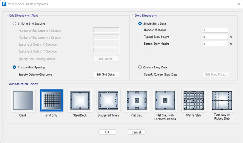
- Click 'Edit Grid Data'
- Assign 'X Spacing' and 'Y Spacing' as shown below
- Click 'OK'
STEP 3: Story Data
- Click 'Custom Story Data'
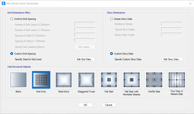
- Click 'Edit Story Data'
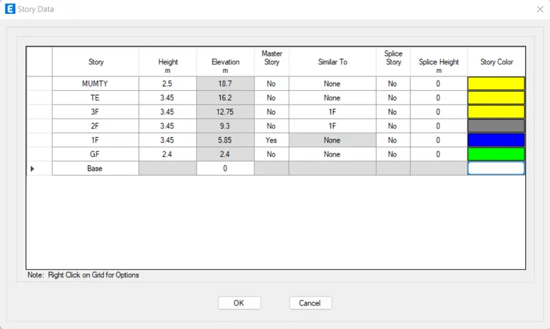
- Assign 'Story' and 'Height' as shown in this figure
- Assign '1F' as the 'Master Story'
- Assign '2F' and '3F Floor' as 'Similar To' '1F'
- Click 'OK'
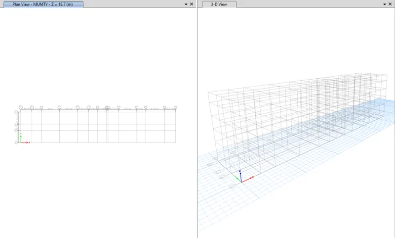
- Click 'OK'
STEP 4: Material Properties
- Click 'Material Properties' under the 'Define' tab

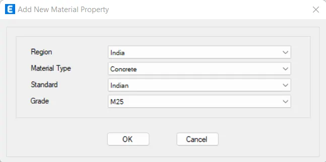
M25
- Click 'Add New Material'
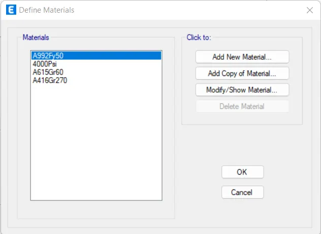
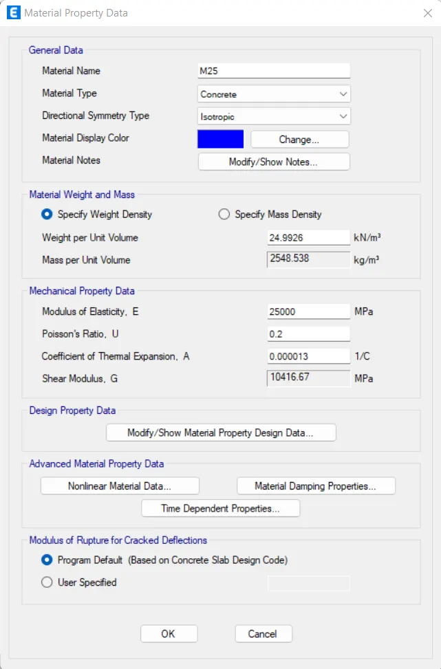
- Assign all options as given below
- Click 'OK'
- Click 'OK'
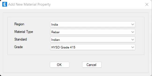
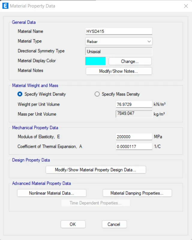
Grade 415
- Again, click 'Add New Material'
- Assign all options as given below
- Click 'OK'
- Click 'OK'
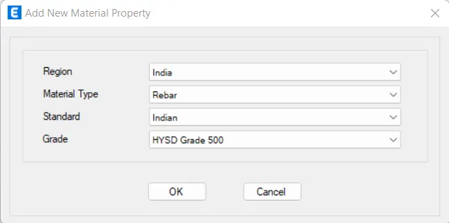
Grade 500
- Again, click 'Add New Material'
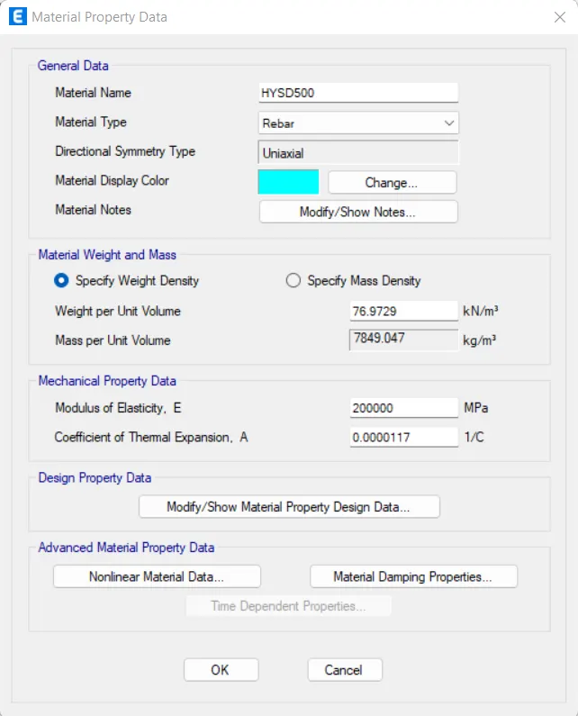
- Assign all options as given below
- Click 'OK'
- Click 'OK'
- Click 'OK'
STEP 5: Add Beam Properties
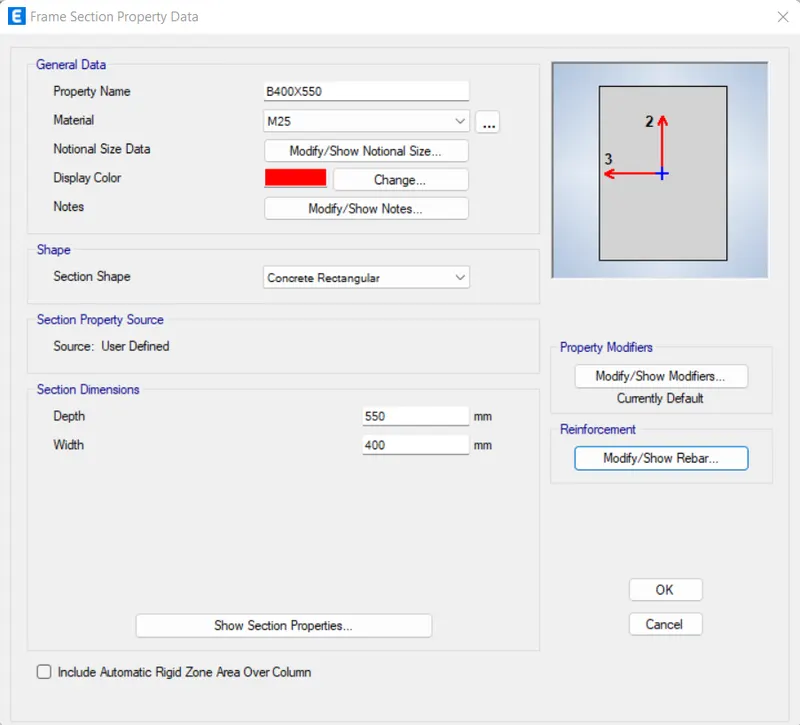
- Click 'Frame Section' in the 'Section Properties' under the 'Define' tab

Beam 400X550
- Click 'Add New Property'
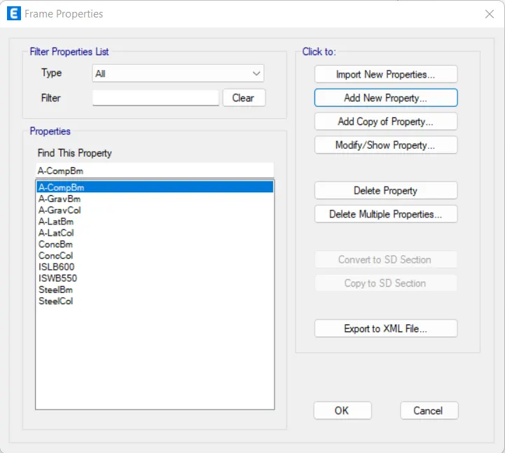
- Click 'Rectangular Section'
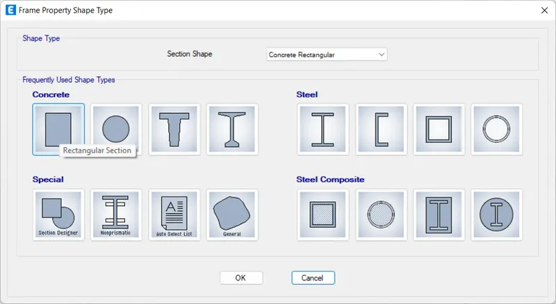
- Assign all options as given below
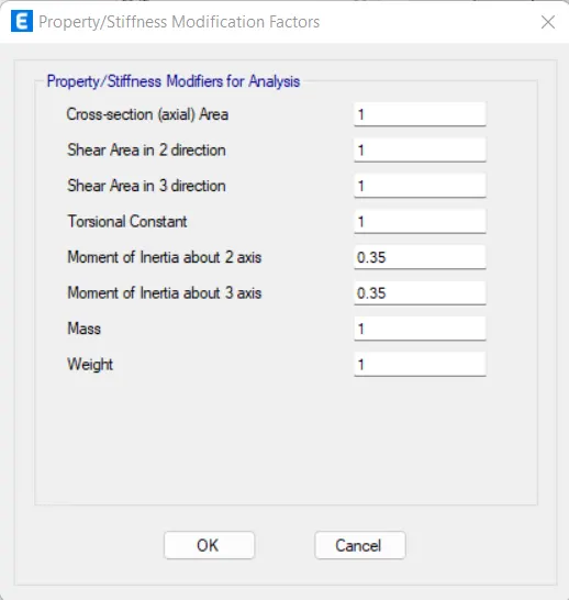
- Click 'Modify/Show Modifiers'
- Assign all options as given below
- Click 'OK'
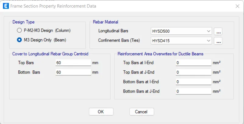
- Click 'Modify/Show Rebar'
- Assign all options as given below
- Click 'OK'
- Click 'OK'
STEP 6: Add Column Properties
- Click 'Frame Section' in the 'Section Properties' under the 'Define' tab
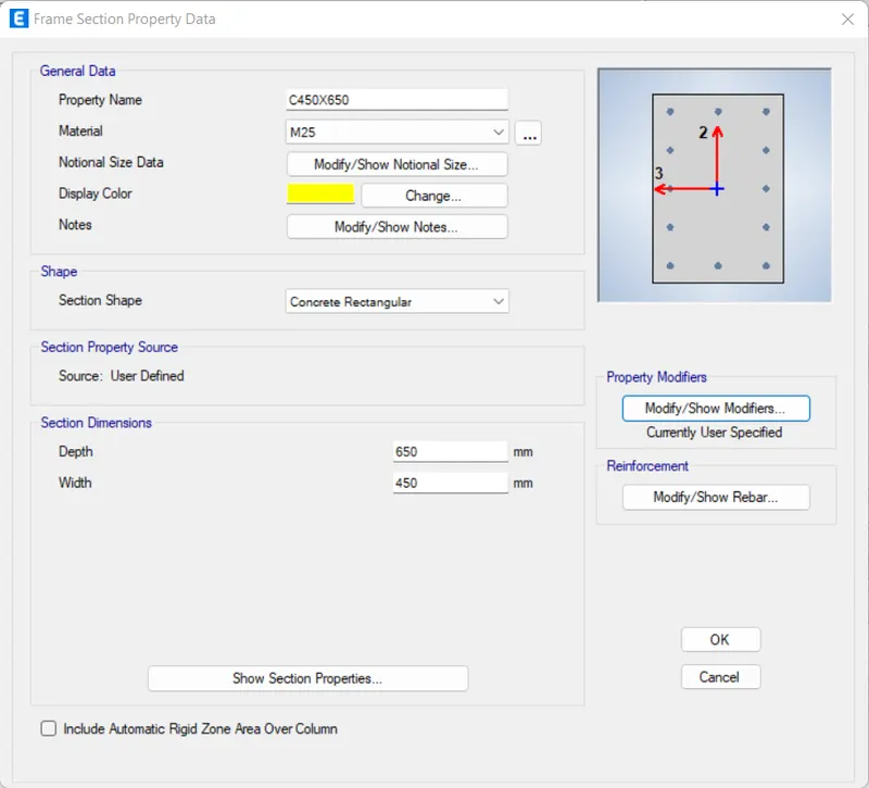
Column 450X650
- Click 'Add New Property'
- Click 'Rectangular Section'
- Assign all options as given below
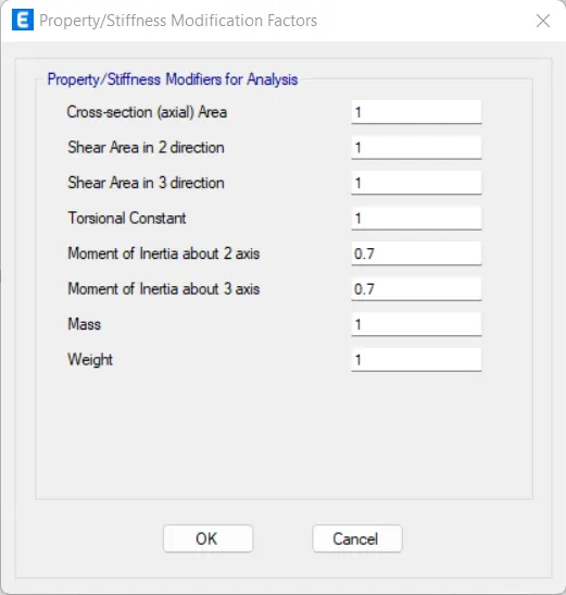
- Click 'Modify/Show Modifiers'
- Assign all options as given below
- Click 'OK'
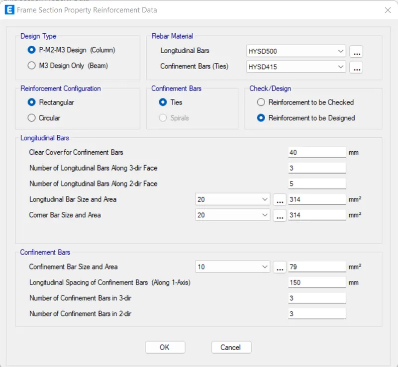
- Click 'Modify/Show Rebar'
- Assign all options as given below
- Click 'OK'
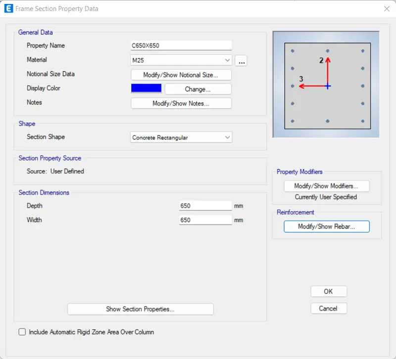
Column 650X650
- Click 'Add New Property'
- Click 'Rectangular Section'
- Assign all options as given below
- Click 'Modify/Show Modifiers'
- Assign all options as given below
- Click 'OK'
- Click 'Modify/Show Rebar'
- Assign all options as given below
- Click 'OK'
STEP 7: Add Slab Properties
- Click 'Slab Section' in the 'Section Properties' under the 'Define' tab
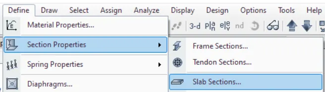
Slab 150mm
- Click 'Add New Property'
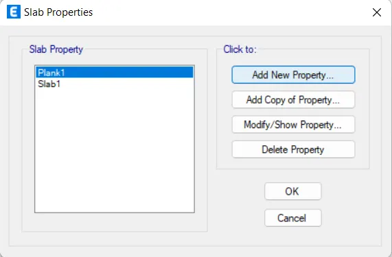
- Assign all options as given below
- Click 'OK'
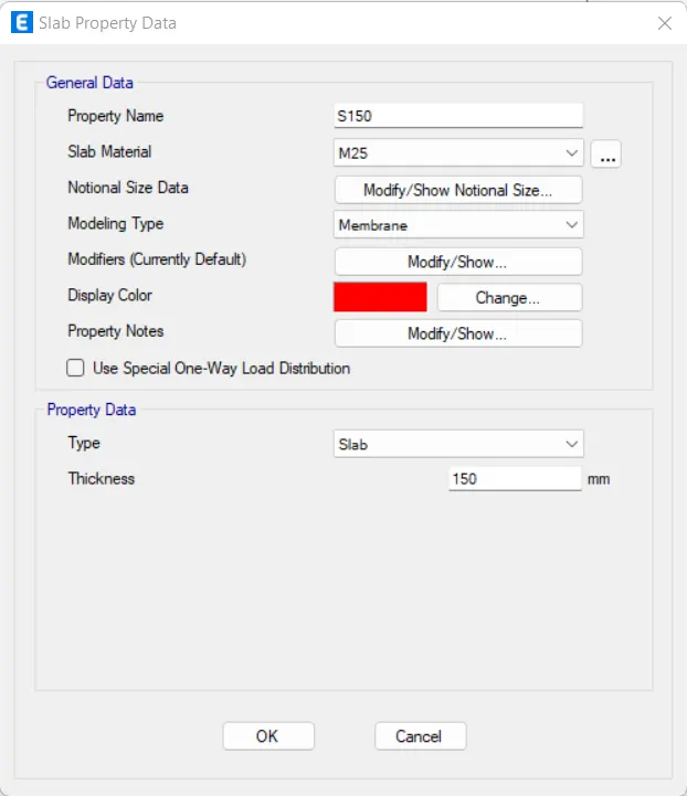
- Click 'OK'
Stair Slab 175mm
- Click 'Add New Property'
- Assign all options as given below
- Click 'OK'
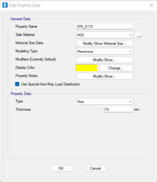
- Click 'OK'
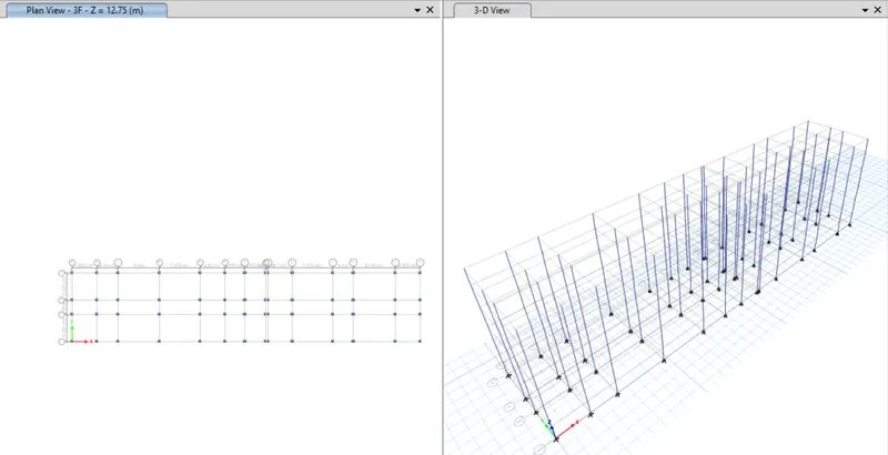
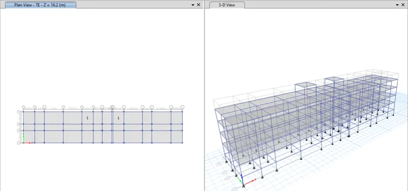
STEP 8: Add Columns, Beams, and Slabs
Columns
- Click 'Quick Draw Columns' from the toolbars
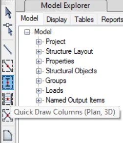
- Select 'All Stories'
- Assign all options as given below
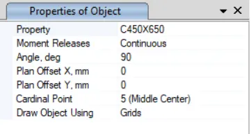
- Place the columns on grids
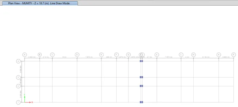
- Assign all options as given below
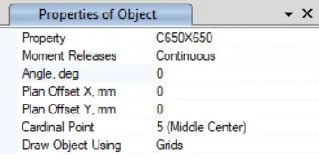
- Place the columns on grids
Beams
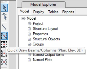
- Click 'Quick Draw Beams' from the toolbars
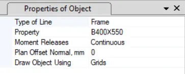
- Assign all options as given below
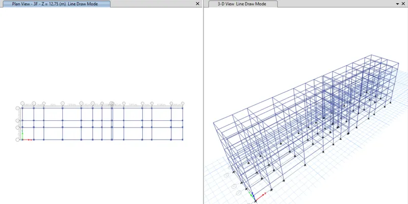
- Place the beams on lines
Slabs
- Click 'Quick Draw Floor/Wall' from the toolbars
- Assign 'S150' as the property
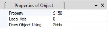
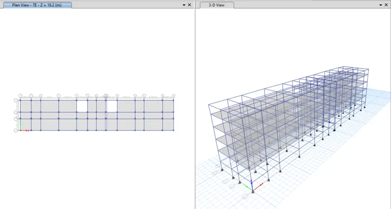
- Click inside the desired grids
- Assign 'STR_S175' as the property
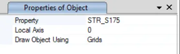
- Click inside the desired grids
STEP 9: Add Load Patterns
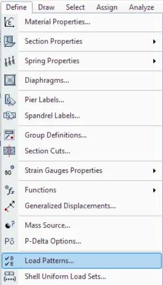
- Click 'Load Patterns' under the 'Define' tab
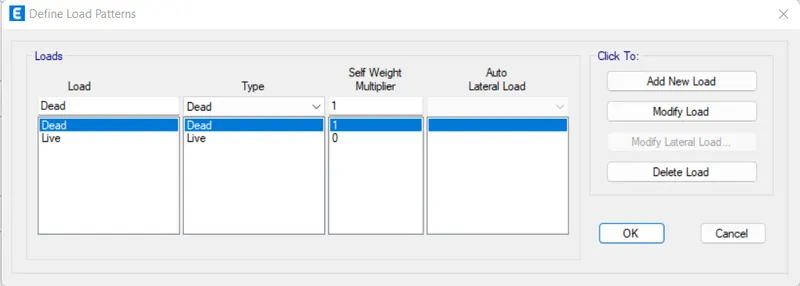
- Apply all loads
- After defining a load, click 'Add New Load'
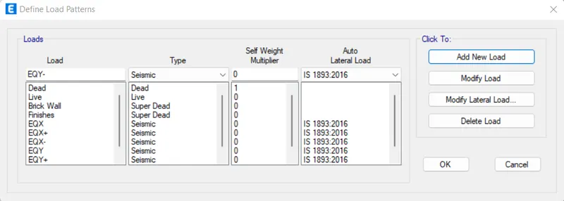
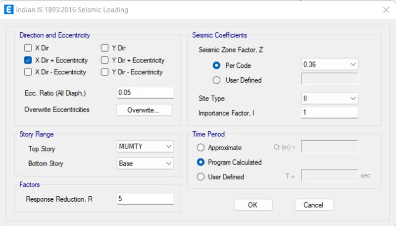
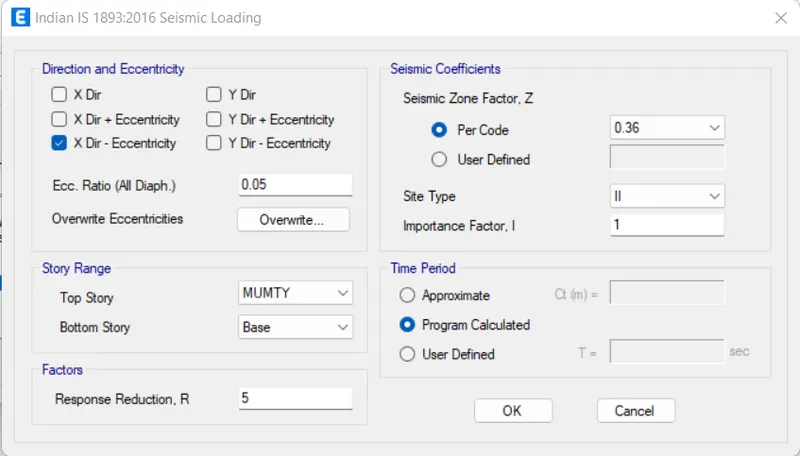
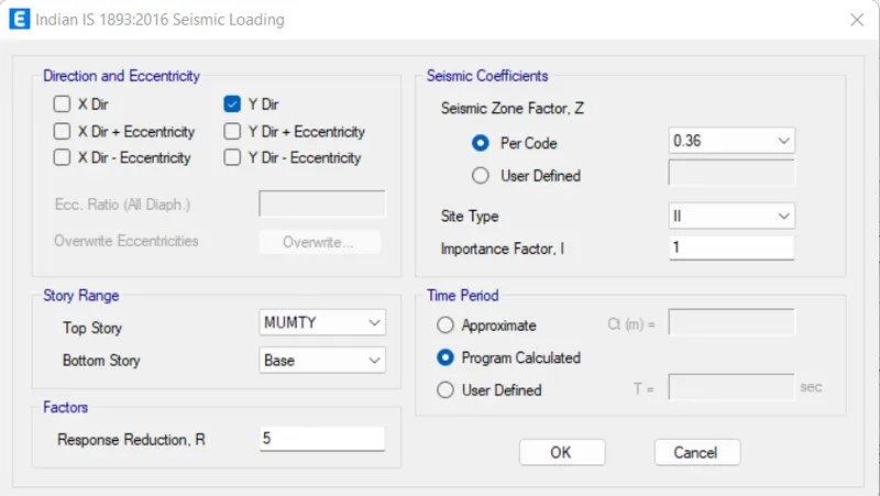
- Click 'Modify Lateral Load' for load 'EQX', 'EQX+', 'EQX-', 'EQY', 'EQY+' and 'EQY-'
- Settings for EQX
- Assign all options as given below
- Click 'OK'
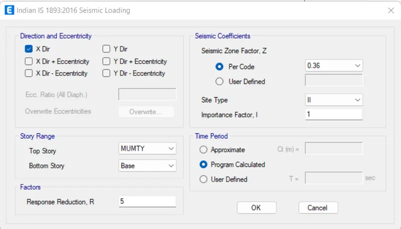
- Settings for EQX+
- Assign all options as given below
- Click 'OK'
- Settings for EQX-
- Assign all options as given below
- Click 'OK'
- Settings for EQY
- Assign all options as given below
- Click 'OK'
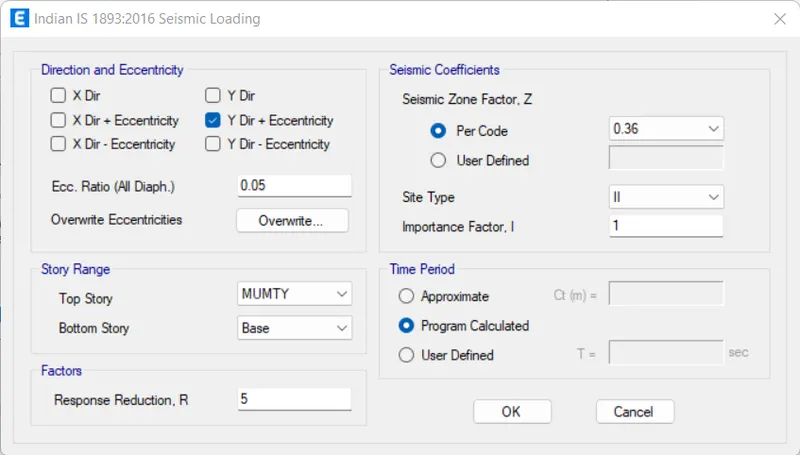
- Settings for EQY+
- Assign all options as given below
- Click 'OK'
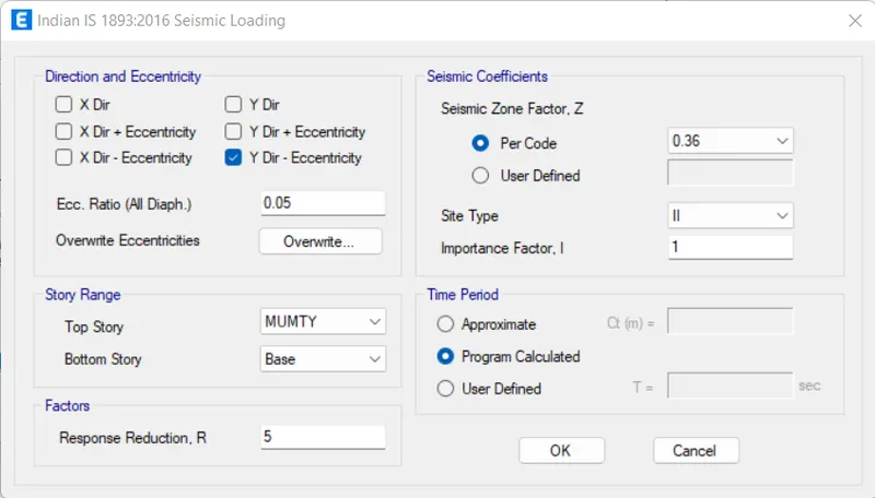
- Settings for EQY-
- Assign all options as given below
- Click 'OK'
- Click 'OK'
STEP 10: Add Mass Source Data
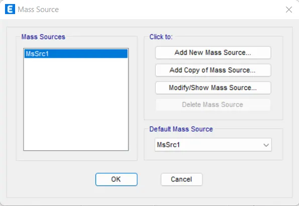
- Click 'Mass Source' under the 'Define' tab

- Click 'Modify/Show Mass Source'
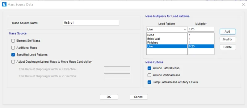
- Assign all options as given below
- Click 'OK'
- Click 'OK'
STEP 11: Assign Loads
Brickwall Load on Floors
- Select beams which undergo brick load
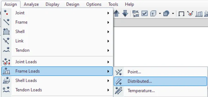
- Click 'Distributed' in the 'Frame Loads' under the 'Assign' tab
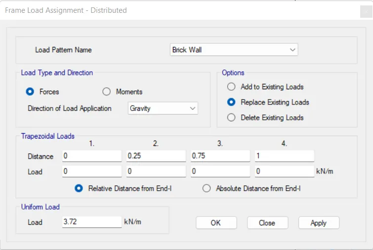
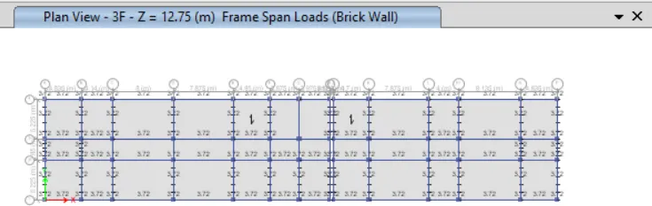
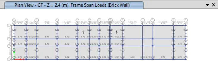
- Assign 'Brick Wall' load as 3.72 KN/m as shown below
- Click 'Apply'
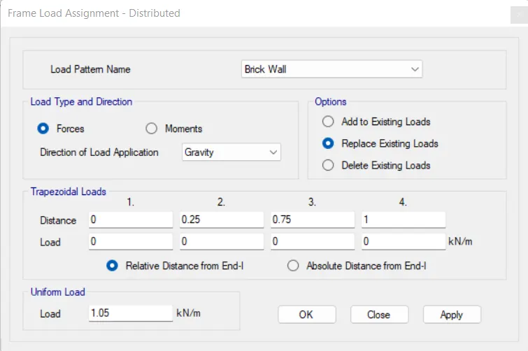
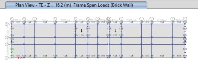
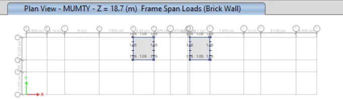
Brickwall Load on Terrace and Mumty
- Select beams which undergo brick load
- Click 'Distributed' in the 'Frame Loads' under the 'Assign' tab
- Assign 'Brick Wall' load as 1.05 KN/m as shown below
- Click 'Apply'
Live Load
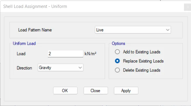
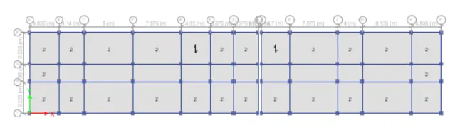
- Select slabs which undergo 2 KN/m2
- Click 'Uniform' in the 'Shell Loads' under the 'Assign' tab
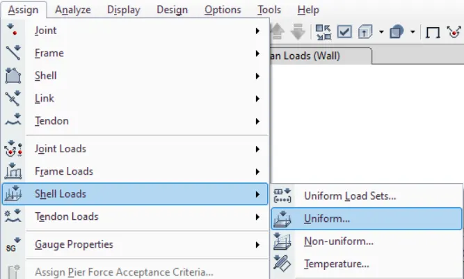
- Assign 'Live' load as 2KN/m2 as shown below
- Click 'Apply'
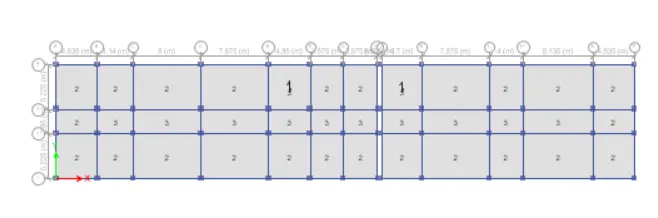
- Select slabs which undergo 3 KN/m2
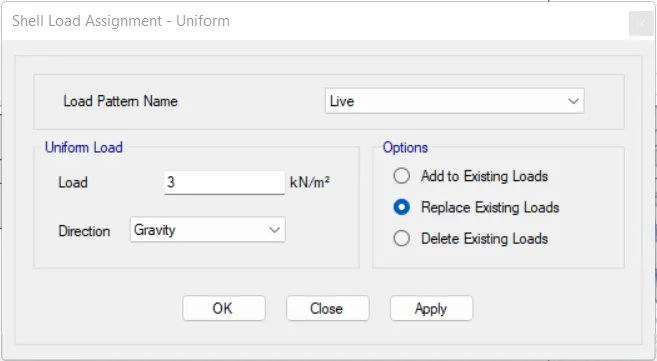
- Click 'Uniform' in the 'Shell Loads' under the 'Assign' tab
- Assign 'Live' load as 3 KN/m2 as shown below
- Click 'Apply'
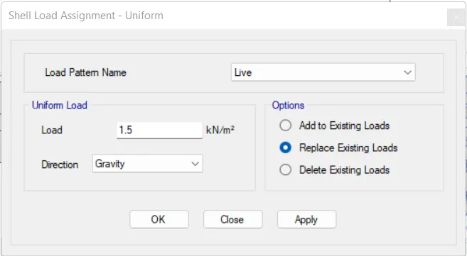
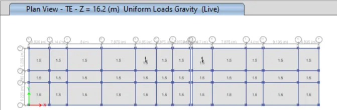
- Select slabs which undergo 3 KN/m2
- Click 'Uniform' in the 'Shell Loads' under the 'Assign' tab
- Assign 'Live' load as 1.5 KN/m2 as shown below
- Click 'Apply'
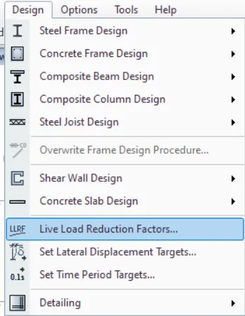
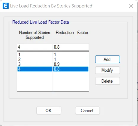
- Click 'Live Load Reduction Factors' underthe 'Design' tab
- Select 'User Defined' and click 'Define'
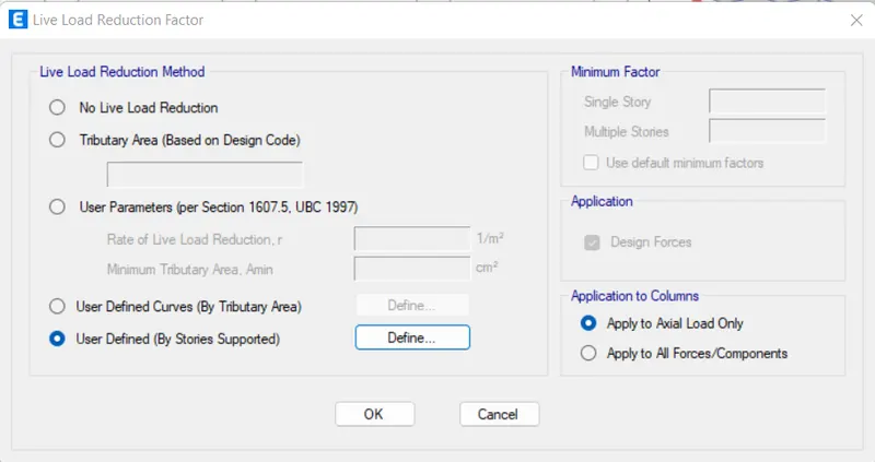
- Assign all values as shown below
- Click 'OK'
- Click 'OK'
Floor Finishes
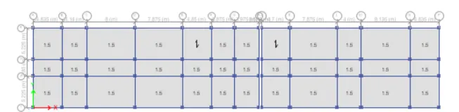
- Select all slabs
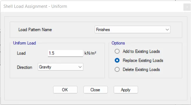
- Click 'Uniform' in the 'Shell Loads' under the 'Assign' tab
- Assign 'Finishes' load as 1.5 KN/m2 as shown below
- Click 'Apply'
Diaphragms
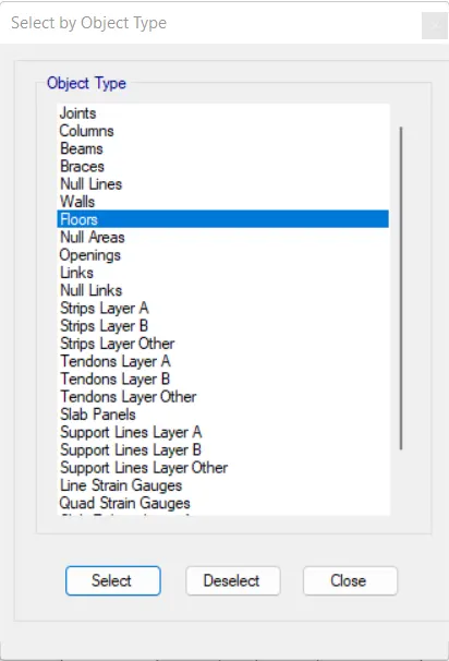
- Click 'Object Type' under the 'Select' tab
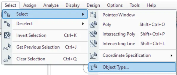
- Click 'Floors' and press 'Select'
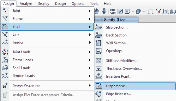
- Click 'Diaphragms' in the 'Shell' under the 'Assign' tab
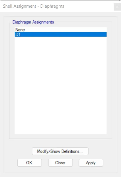
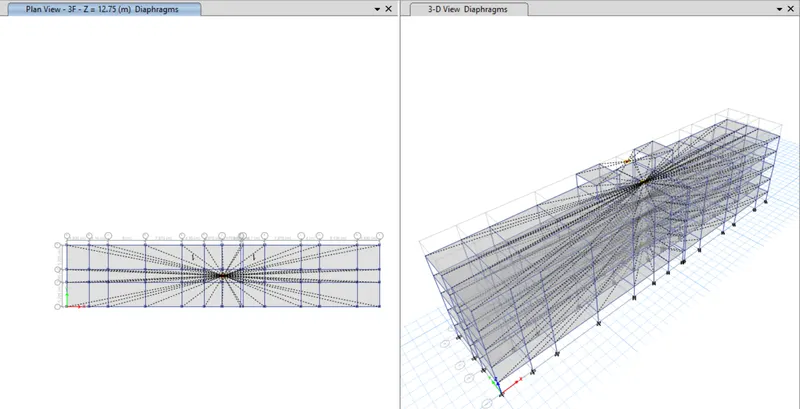
- Select 'D1' and click 'Apply'
STEP 12: Modal Cases
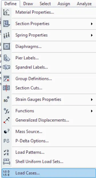
- Click 'Load Cases' under the 'Define' tab
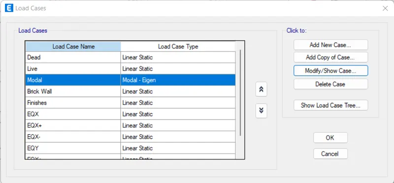
- Click 'Modify/Show Case'
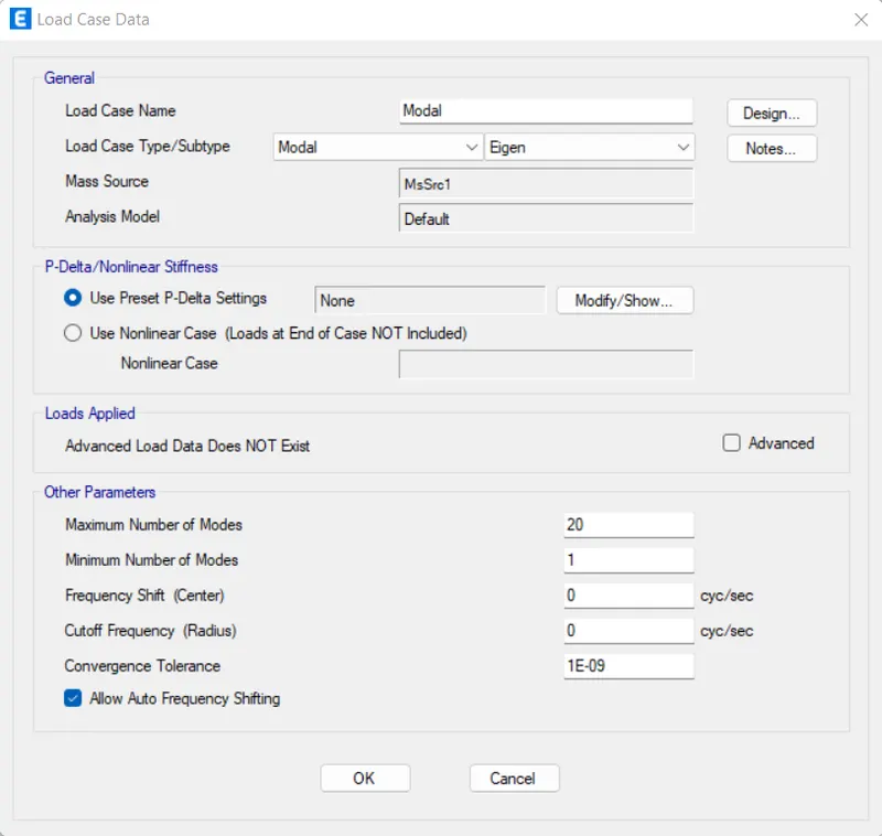
- Assign all values as shown below
- Click 'OK'
- Click 'OK'
STEP 13: Response Spectrum
- Click 'Response Spectrum' in the 'Functions' under the 'Define' tab
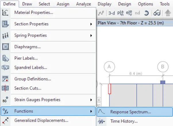
- Select 'IS 1893:2016' and click 'Add New Function'
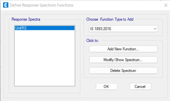
- Assign all values as shown below
- Click 'OK'
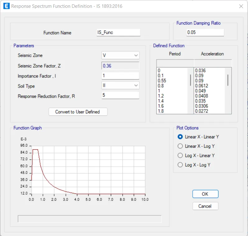
- Click 'OK'
- Click 'Load Cases' under the 'Define' tab
- Click 'Add New Case'
- Assign all values as shown below
- Click 'OK'
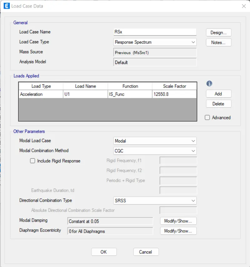
- Again, click 'Add New Case'
- Assign all values as shown below
- Click 'OK'
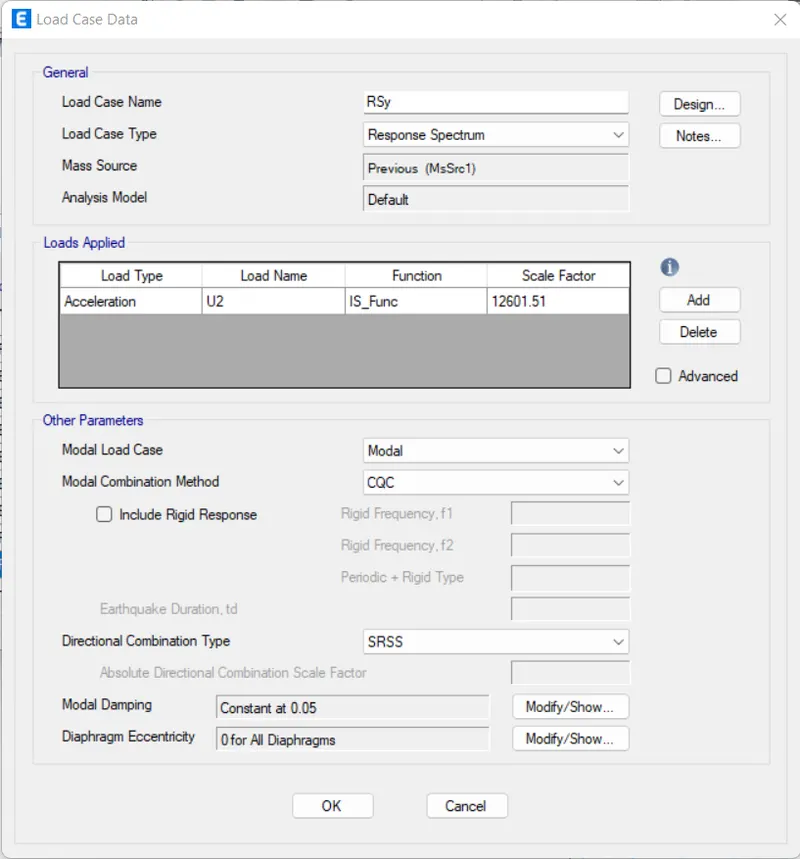
- Click 'OK'
STEP 14: Load Combinations
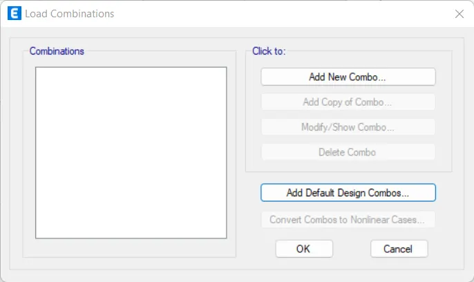
- Click 'Load Combinations' under the 'Define' tab
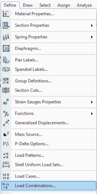
- Click 'Add Default Design Combos'
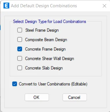
- Select 'Concrete Frame Design', and 'Convert to User Combinations'
- Click 'OK'
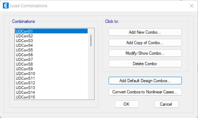
- Click 'OK'
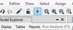
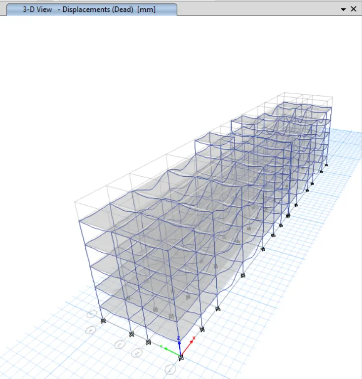
STEP 15: Run Analysis
- Click 'Run Analysis' from top menu
STEP 16: Model Tables
- From 'Model Explorer', select
- ANALYSIS RESULTS > Structure Output > Base Reactions > Table: Base Reactions
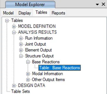
- Right click and then click 'Show Table'
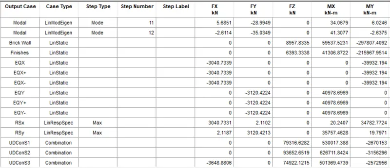
EQX and EQY values equal to RSx and RSy values
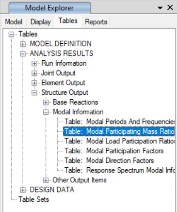
- From 'Model Explorer', select
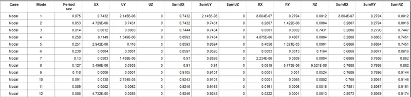
- ANALYSIS RESULTS > Structure Output > Modal Information > Table: Modal Participating Mass Ratio
- Right click and then click 'Show Table'
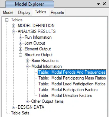
- From 'Model Explorer', select
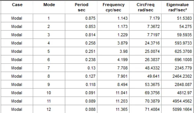
- ANALYSIS RESULTS > Structure Output > Modal Information > Table: Modal Periods And Frequencies
- Right click and then click 'Show Table'
STEP 17: Story Response Plots
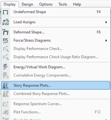
- Click 'Story Response Plots' under the 'Display' tab
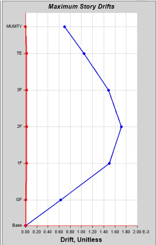
- Assign 'Display Type' as 'Max story drifts' and 'Case/Combo' as 'EQX'
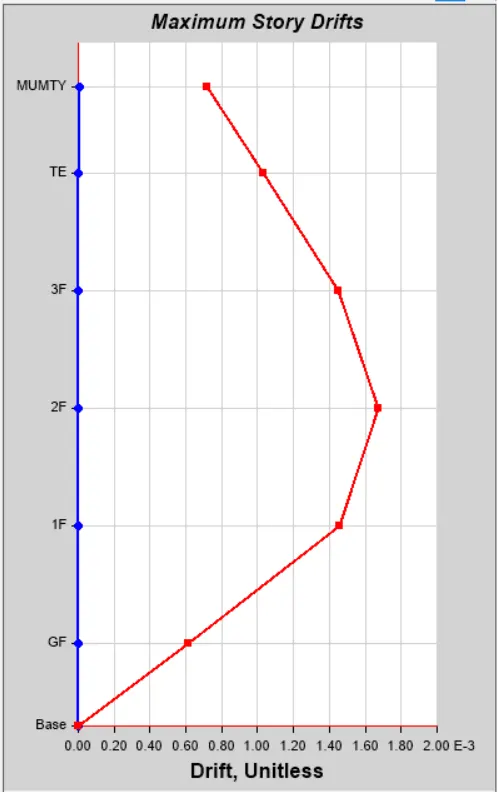
- Assign 'Display Type' as 'Max story drifts' and 'Case/Combo' as 'EQY'
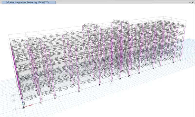
STEP 18: Longitudinal Reinforcing
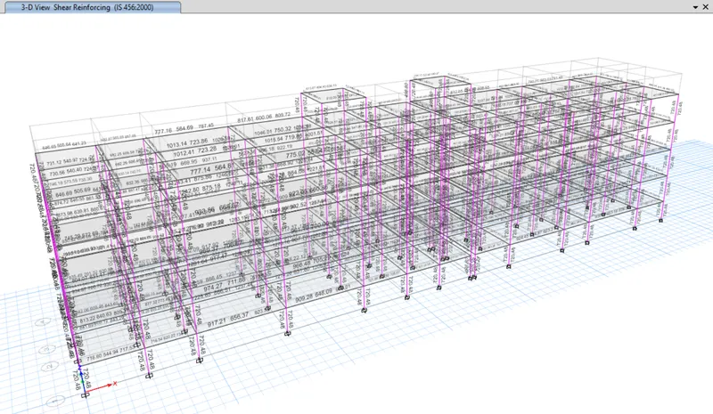
STEP 19: Shear Reinforcing
STEP 20: Export to SAFE File
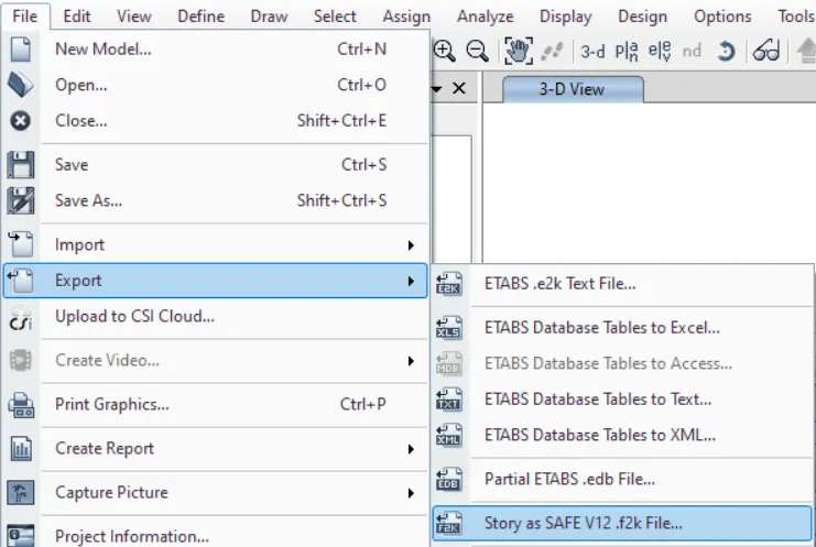
- Click 'Story as SAFE V12 .f2k File' in the 'Export' option under the 'File' tab
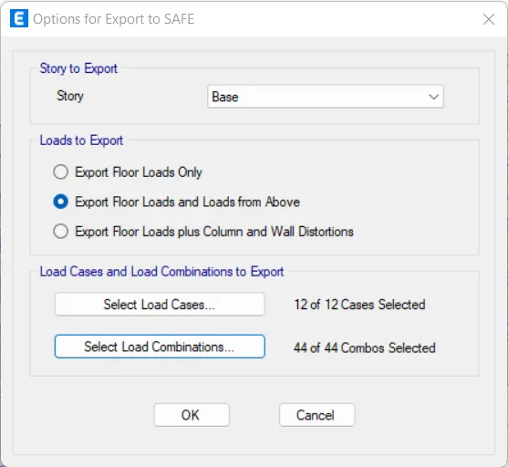
- Assign all values as shown below
- Click 'OK'
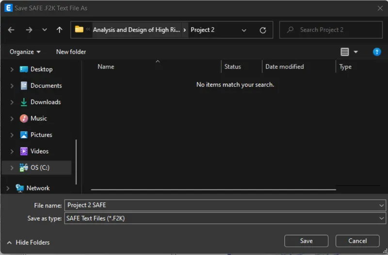
- Give file name and click 'Save'
2) SAFE
- Open SAFE Software
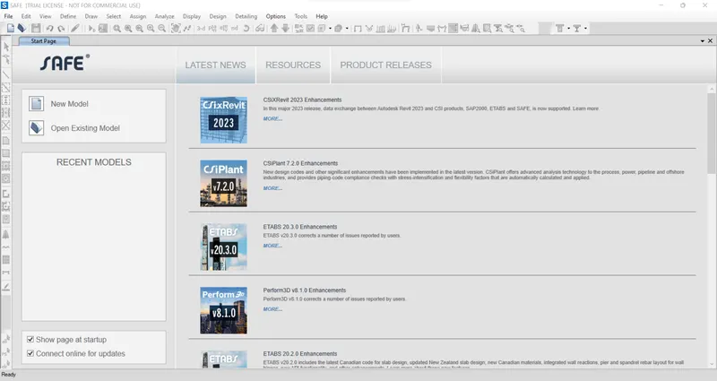
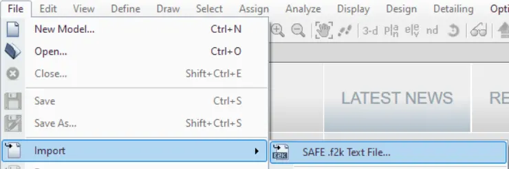
STEP 1: Import the SAFE File
- Click 'SAFE .f2k Text File'
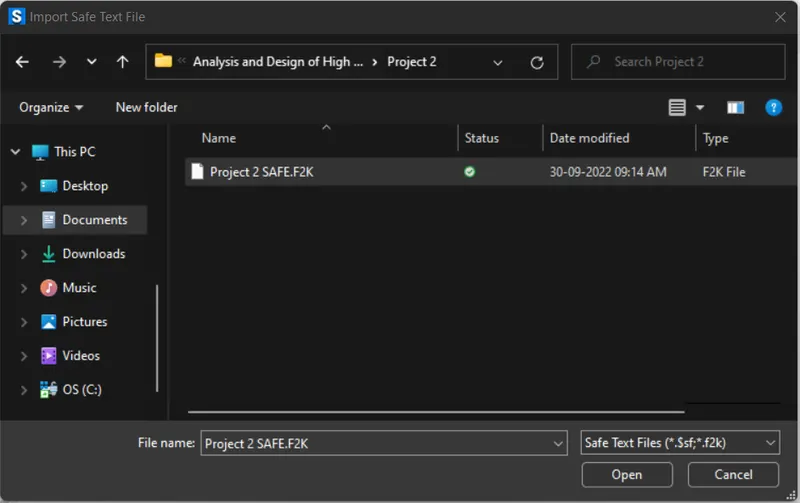
- Select the file and click 'Open'
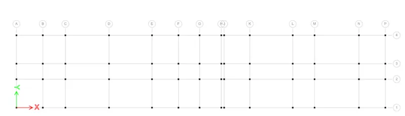
STEP 2: Material Properties
- Click 'Material Properties' under the 'Define' tab
M25
- Click 'Add New Material'
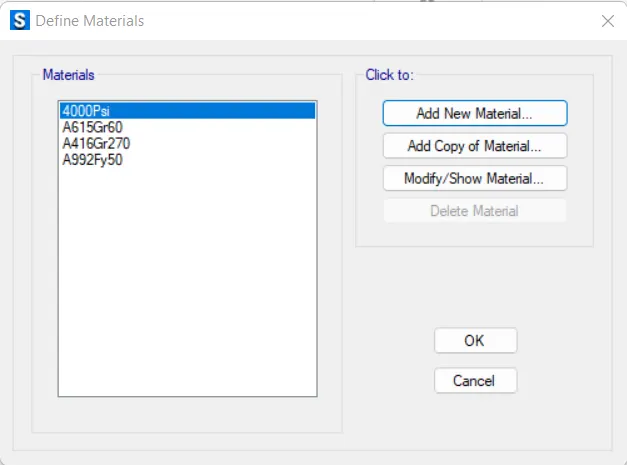
- Assign all options as given below
- Click 'OK'

- Assign all options as given below
- Click 'OK'
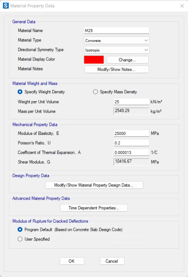
Grade 500
- Click 'Add New Material'
- Assign all options as given below
- Click 'OK'
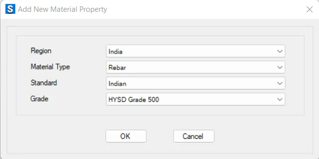
- Assign all options as given below
- Click 'OK'
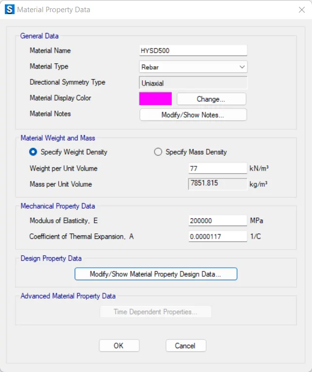
- Click 'OK'
STEP 3: Add Slab and Tie Beam Properties
- Click 'Slab Section' in the 'Section Properties' under the 'Define' tab
Pile Cap
- Select 'Footing1' and click 'Modify/Show Property'
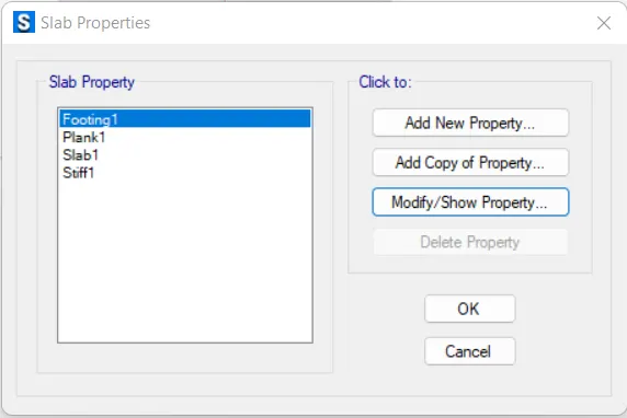
- Assign all options as given below
- Click 'OK'
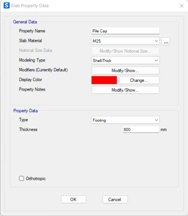
- Click 'OK'
Column
- Select 'Stiff1' and click 'Modify/Show Property'
- Assign all options as given below
- Click 'OK'
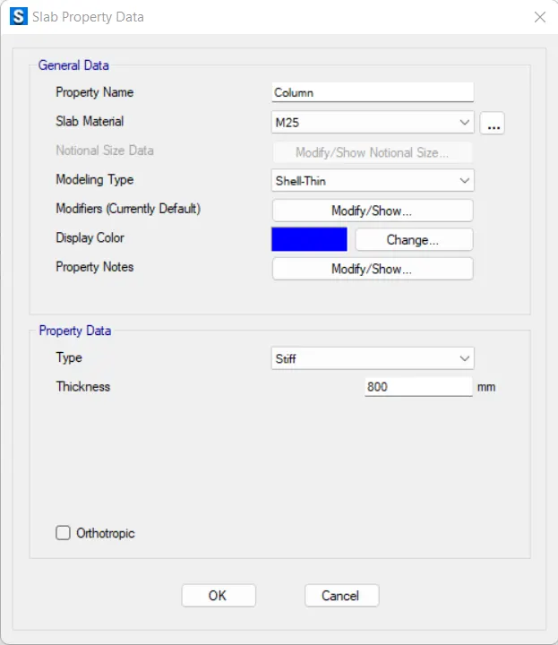
- Click 'OK'
Piles
- Click 'Add New Property'
- Assign all options as given below
- Click 'OK'
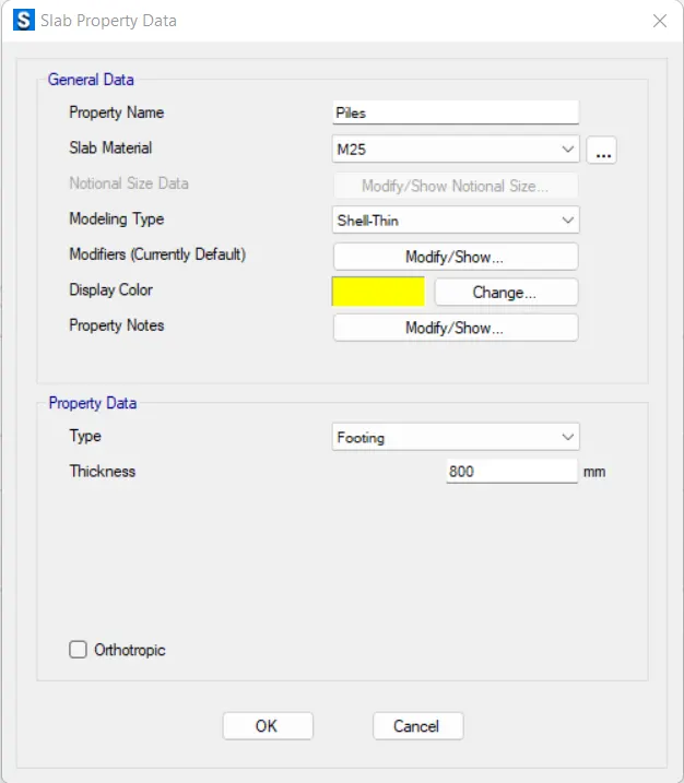
- Click 'OK'
- Click 'Frame Section' in the 'Section Properties' under the 'Define' tab
Tie Beam
- Click 'Add New Property'
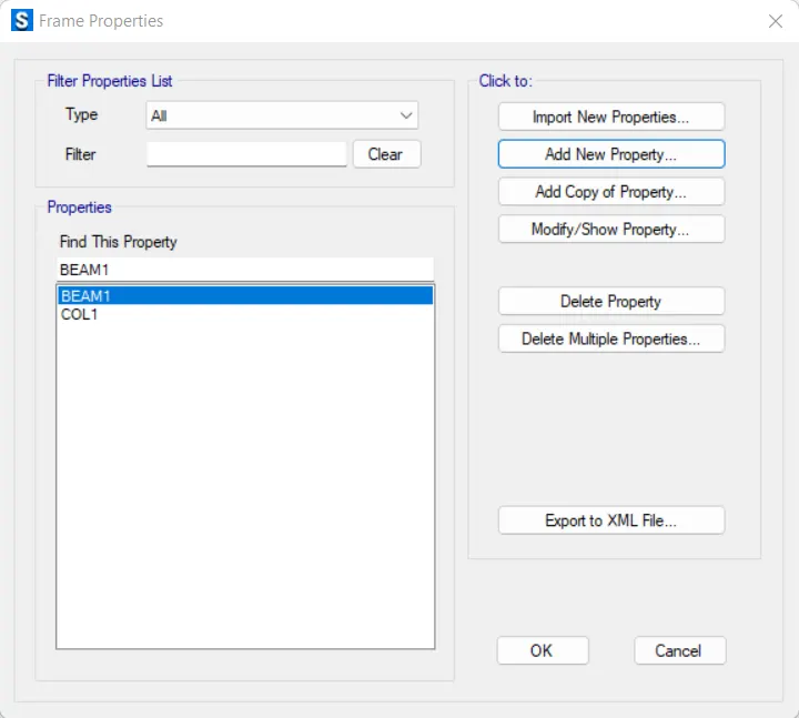
- Select 'Rectangular Section' and click 'OK'
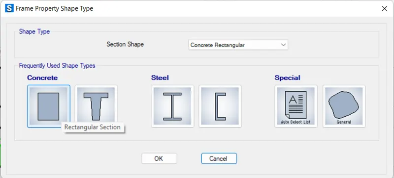
- Assign all options as given below
- Click 'OK'
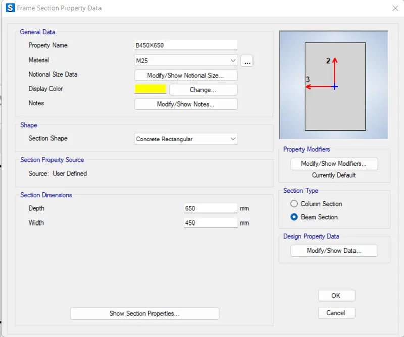
- Click 'OK'
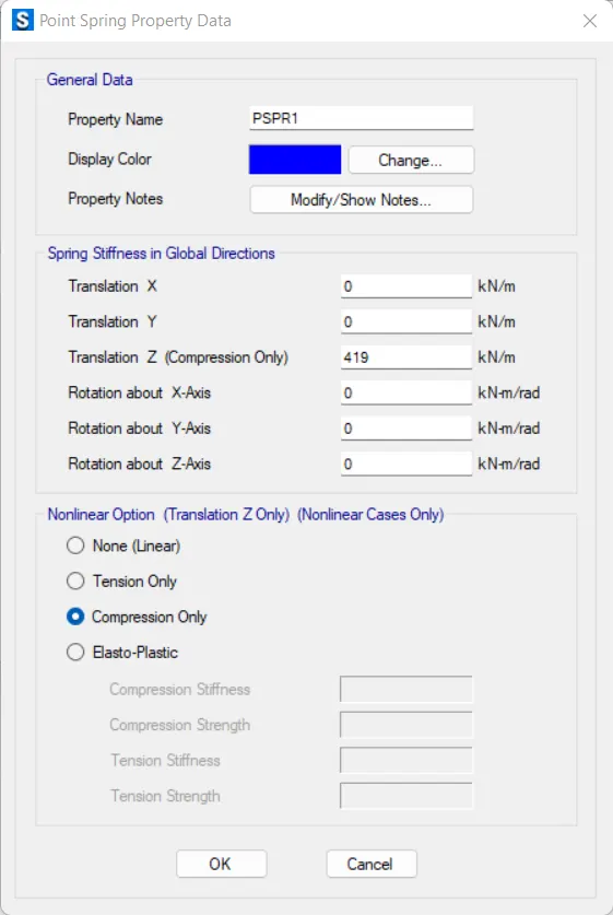
STEP 4: Add Point Spring Property Data
- Click 'Point Springs' in the 'Spring Properties' under the 'Define' tab
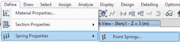
- Assign all options as given below
- Click 'OK'
STEP 5: Draw Slab Properties
- Click 'Quick Draw Area Around Point'
- Assign all options as given below
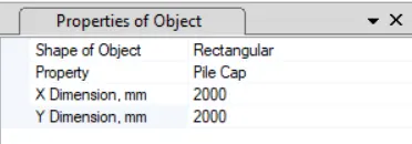
- Click all the necessary points
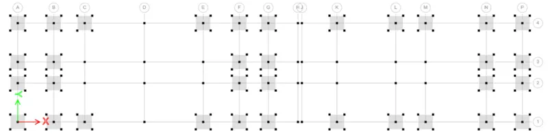
- Assign all options as given below
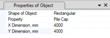
- Click all the necessary points
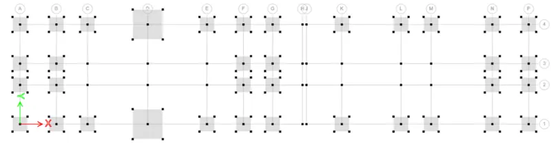
- Assign all options as given below
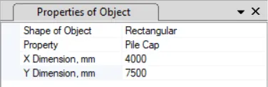
- Click all the necessary points
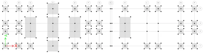
- Assign all options as given below
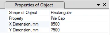
- Click all the necessary points
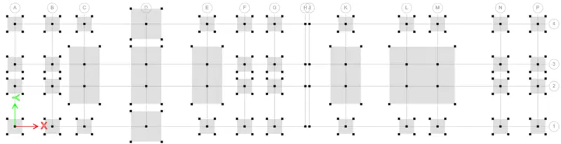
- Assign all options as given below
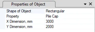
- Click all the necessary points
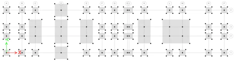
STEP 6: Add Piles and Column
- Click 'Quick Draw Area Around Point'
- Assign all options as given below
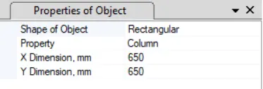
- Draw column in the center point
- Assign all options as given below
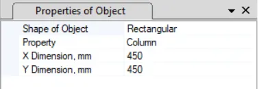
- Draw column in the center point
- Assign all options as given below
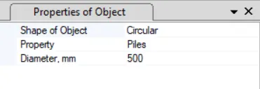
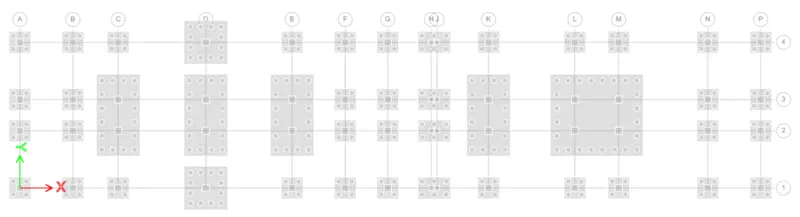
- Draw the pile caps in the reference points
STEP 7: Assign Point Springs
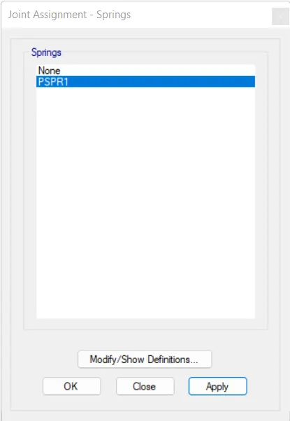
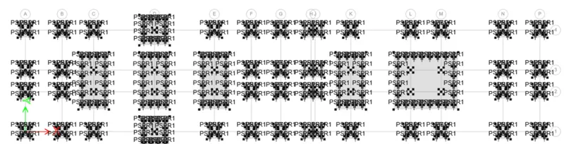
- Select the center points of all piles
- Click 'Springs' in the 'Joint' under the 'Assign' tab

- Select 'PSPR1' and click 'OK'
STEP 8: Assign Tie Beam
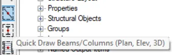
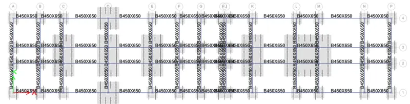
- Click 'Quick Draw Beams'
- Click on each frame to assign beams
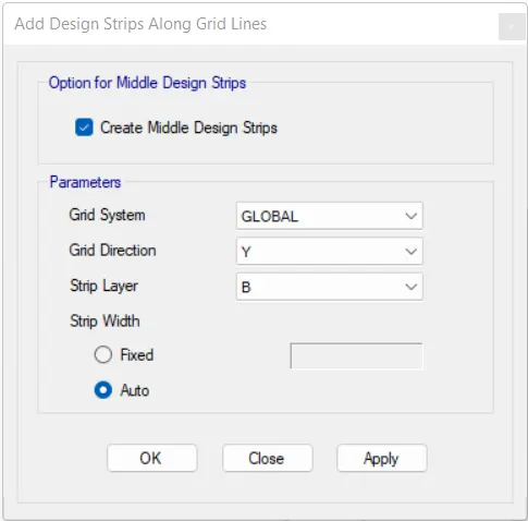
STEP 9: Design Strips
- Click 'Add Design Strips' under the 'Edit' tab
- Assign all options as given below
- Click 'OK'
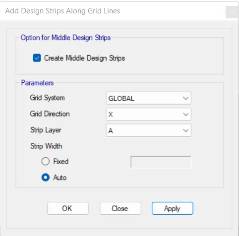
- Assign all options as given below
- Click 'OK'
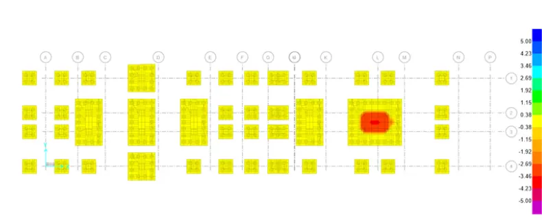
STEP 10: Run Analysis
- Click 'Run Analysis' from top menu
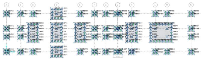
STEP 11: Punching Shear
- Click 'Show Punching Shear Design' in the top menu
STEP 12: Top and Bottom Reinforcement
- Click 'Slab Design' in the top menu
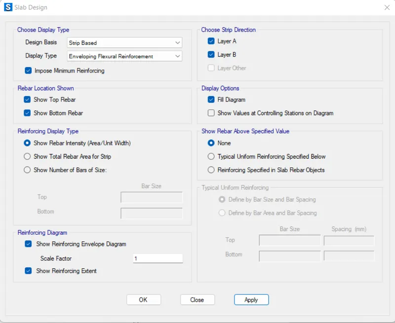
- Assign all options as given below
- Click 'OK'
Layer A
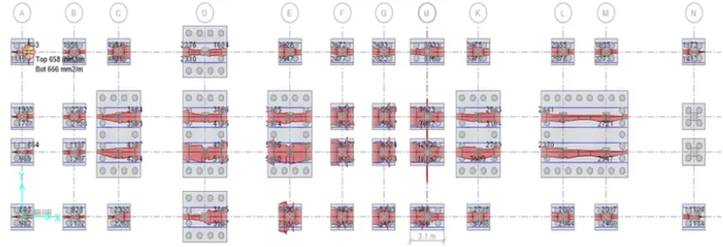
Layer B
RESULTS
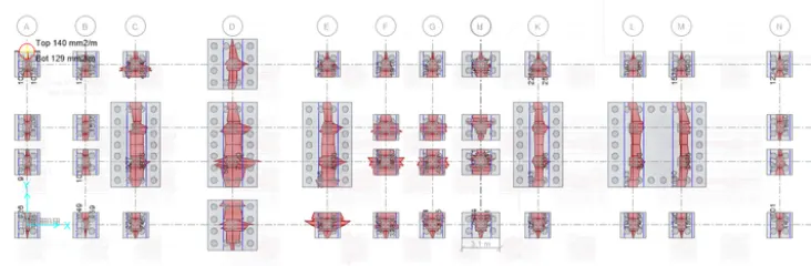
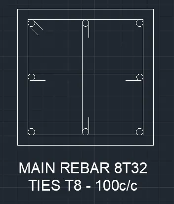
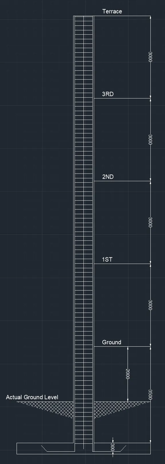
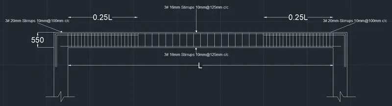
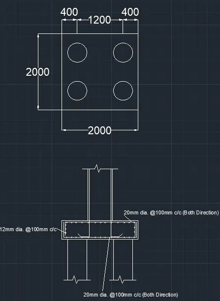
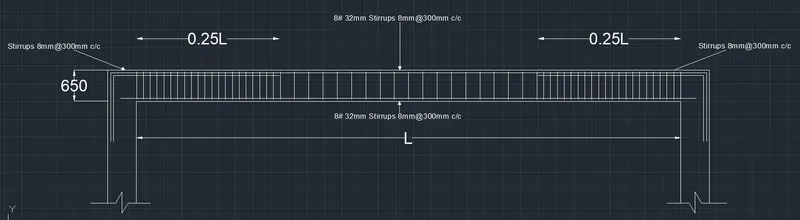
A G+3 Hostel block in Guwahati, Assam is designed and analysed in ETABS and SAFE. The graphs and tables for the checks are given in the procedure. All checks are achieved. Column reinforcement, Beam Reinforcement, pile cap reinforcement, Tie beam details and framing plan for typical floor are given below
Typical Column Reinforcement
Typical Beam Reinforcement
Typical Pile Cap Reinforcement
Typical Tie Beam Reinforcement
Framing plan for typical floor