Project 2_Design & Analysis of a Hostel building at Guwahati, Assam
ANS :
AIM : To design and analyze od G + 3 hostel building Guwahati Assam by Etabs and safe software
PROCEDURE :
Step 1 : DATA REQUIRED FOR ETABS ANALYSIS
Consider the supports as pinned support and story height as Base + 5 story + Mumty
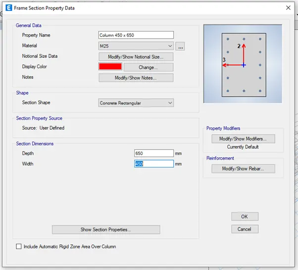
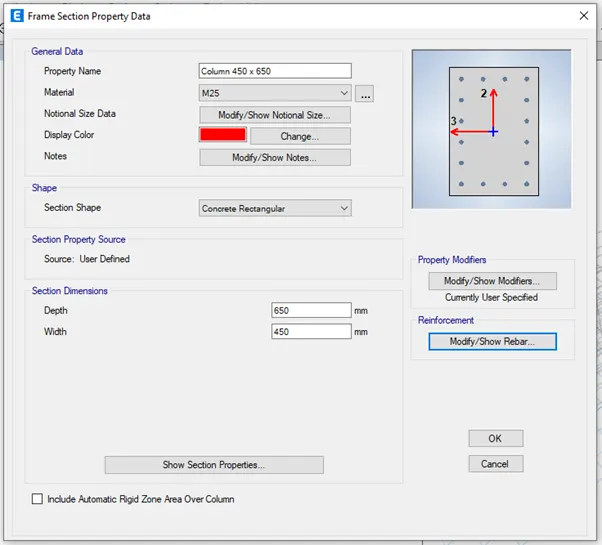
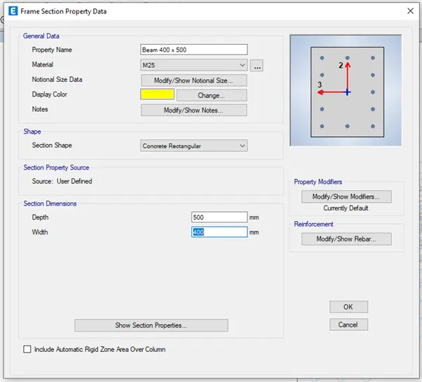
Column size as 450 x 650 mm, Beam size as 400 x 500 mm, Slab thickness as 150 mm and there is no requirement as shear wall
Now we have to consider loads acting on the building
Floor live load = 2 KN/mmsq
Terrace live load = 1 KN/mmsq
Floor finish + Ceiling finish = 1 KN/mmsq
Partition wall load = 3.5 KN/m
Balcony wall load = 1 KN/m
Guwahati seismic zone is zone V
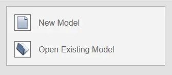
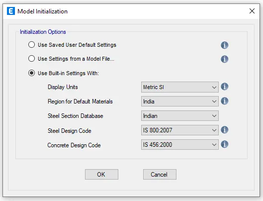
Step 2 : Open then Etabs software and click on new model, the model initialization dialogue box will appear in that select use Built-in settings with and make the settings accordingly and press ok
New model quick template dialogue box will appear
In the dialogue box select custom grid spacing in grid dimension and select custom story data in story dimension
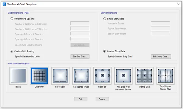
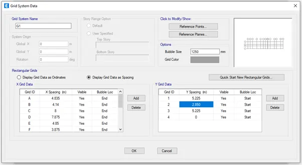
In custom grid spacing click on edit grid data you will get the grid system data dialogue box
Give the data according to the question given in both x and y direction
As per the question the spacing between the grids both x and y direction and give other data accordingly and press ok
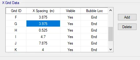
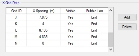
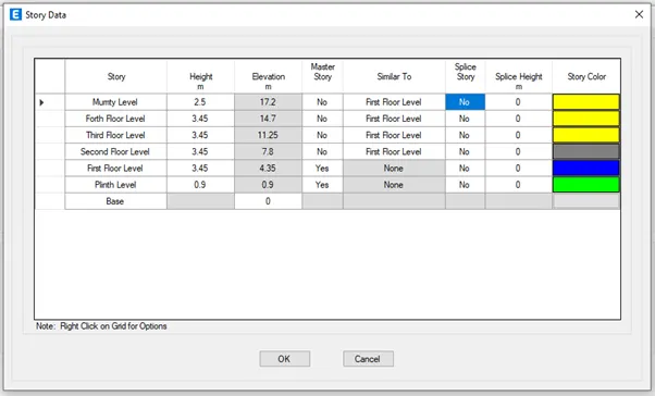
In custom story data click on edit story data you will get the story data dialogue box
Add the story as per the given question given
Give the master story as first story and for other story give similar to as first story
By right clicking the arrow given in top row add the required amount of story and do the settings accordingly and press ok
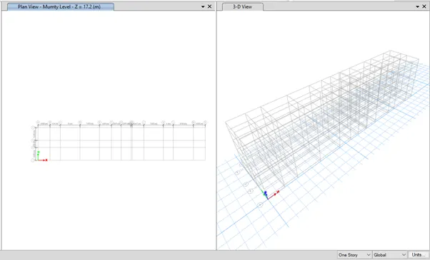
Step 3 : Go to define tab and select material properties
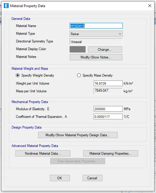
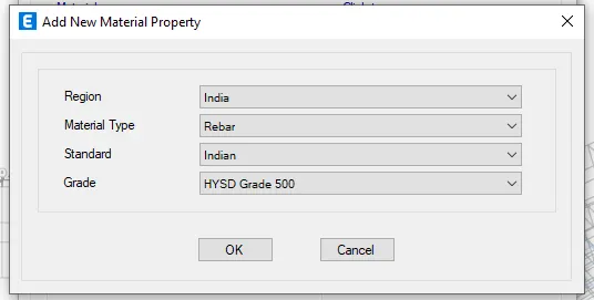
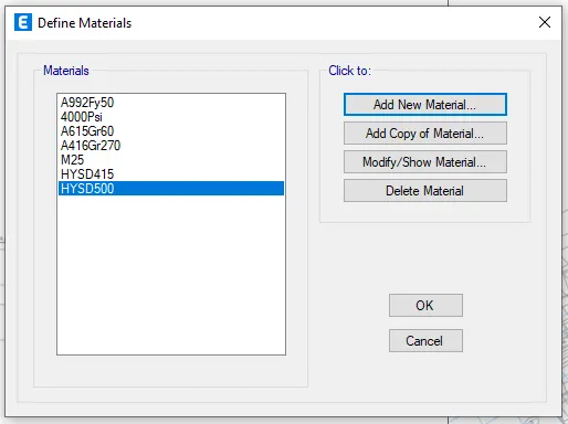
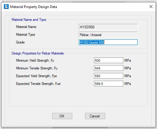
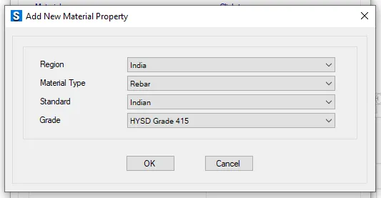
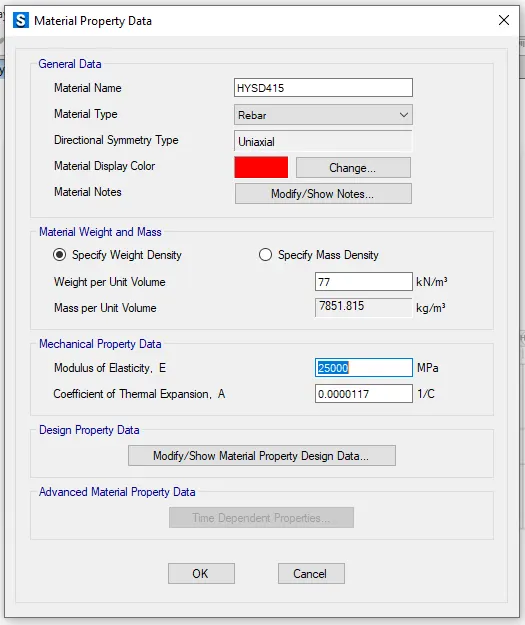
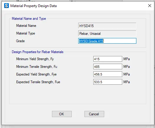
Add grade of concrete as M25 and Grade of steel reinforcement bars as Fe415, Grade of steel reinforcement bars as Fe500 and do the settings accordingly for each material
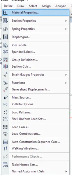
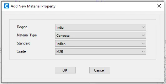
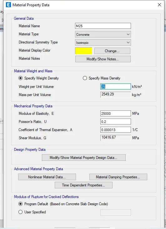
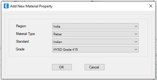

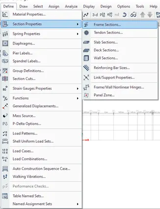
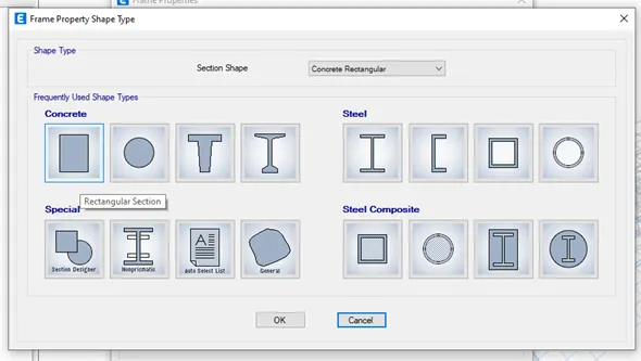
Step 4 : Go to define tab and select section properties in that select frame sections
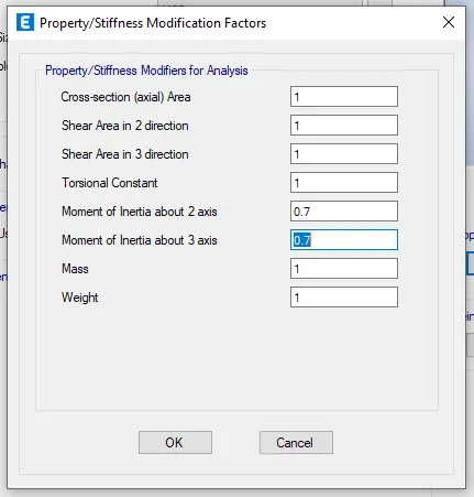
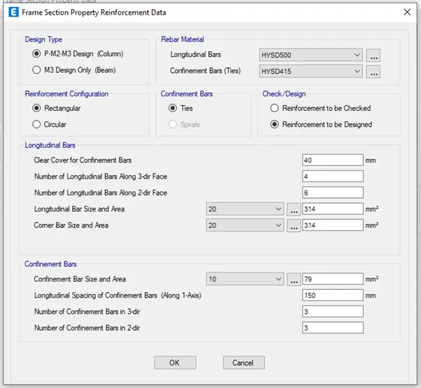
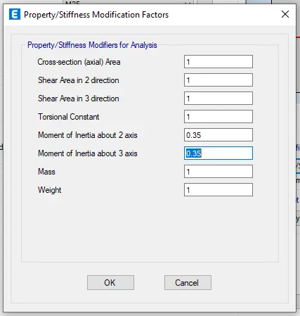
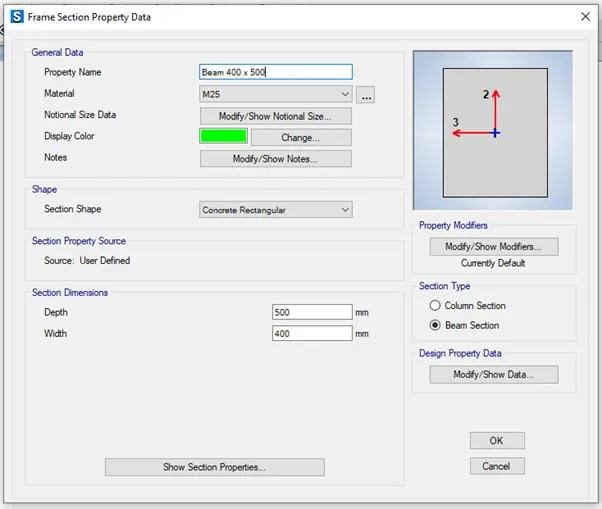
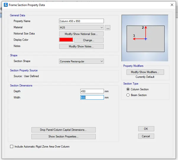
Add column of size 450 x 650 mm and beam of size 400 x 500 mm properties as per the question by clicking on Add new property
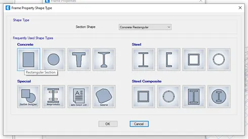
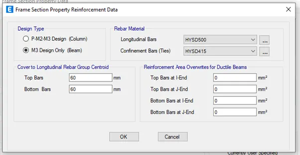
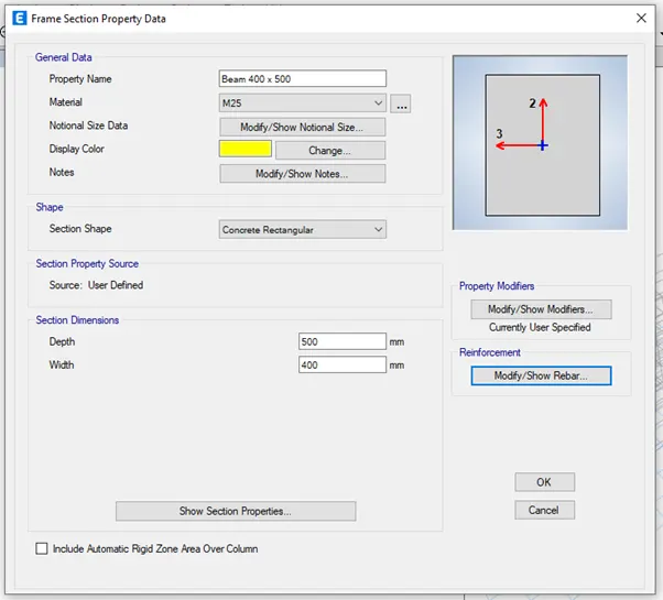
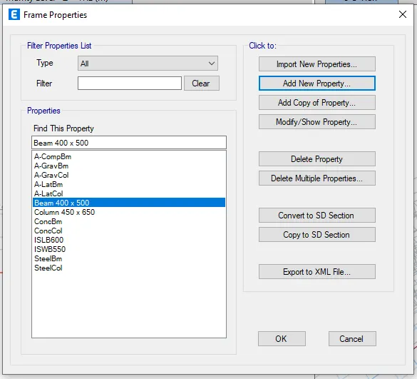
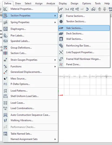
Go to define tab and select section properties in that select slab sections
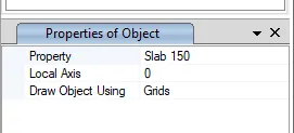
Add slab of 150mm thick as per the question by clicking on Add new property
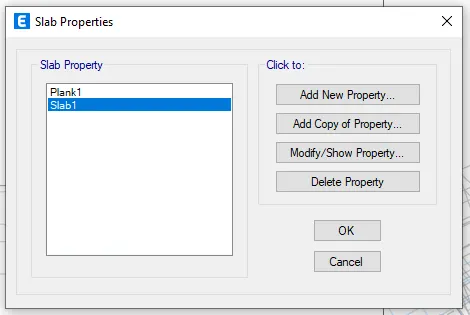
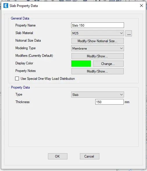
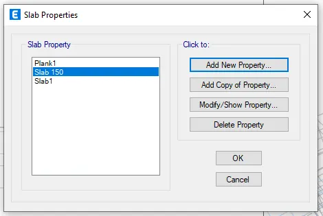
Step 5 : Draw the column 450 x 650 at each intersection of the grid by selecting Quick draw column
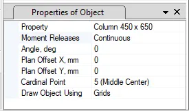
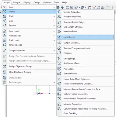
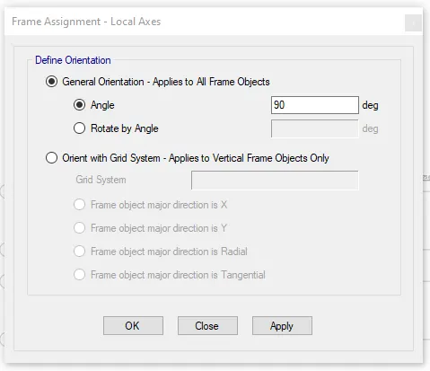
Go to Assign tab in that select frame and select local axes and rotate the columns wherever needed by 90 degree
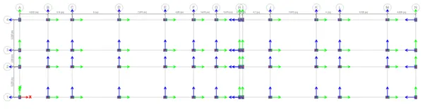
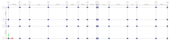
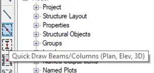
Draw the beam 400 x 500 at grid line by selecting Quick draw beam
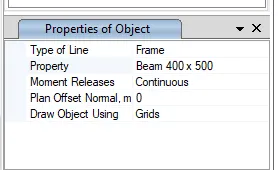
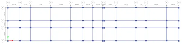
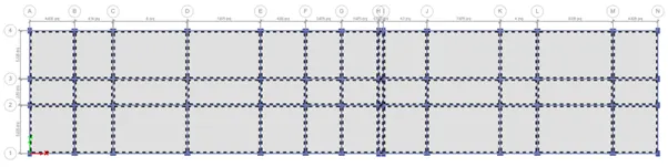
Draw slab of 150mm by selecting quick draw floor
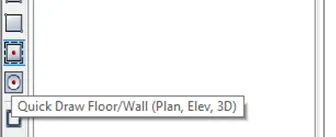
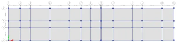
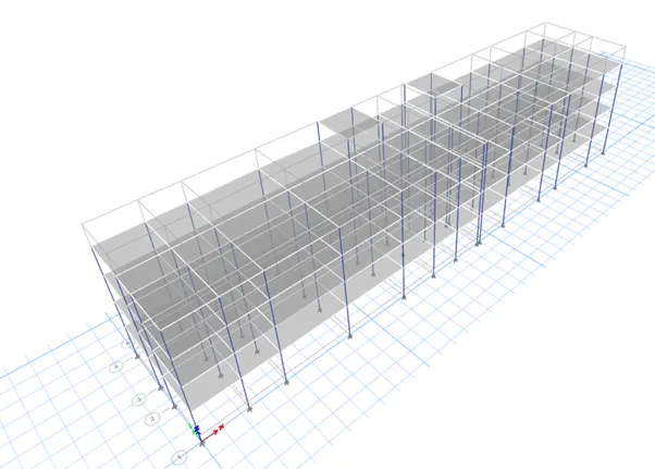
Step 6 : Go to base and select all the joints
Go to assign tab select joint in that select restaints and select pinned support for all the directions and click on apply
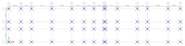
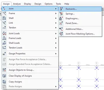
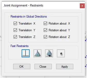
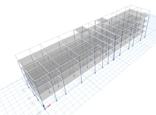
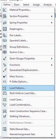
Step 7 : Go to define and select the load pattern
Add the loads like dead load, live load, brickwall load and earthquake load both in x and y direction in positive and negative direction
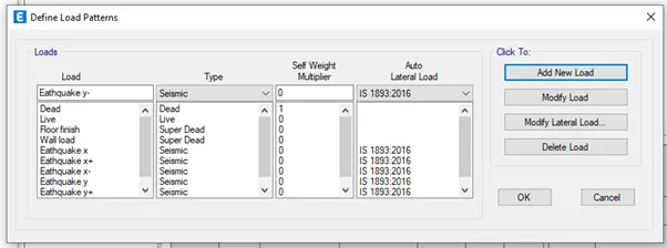
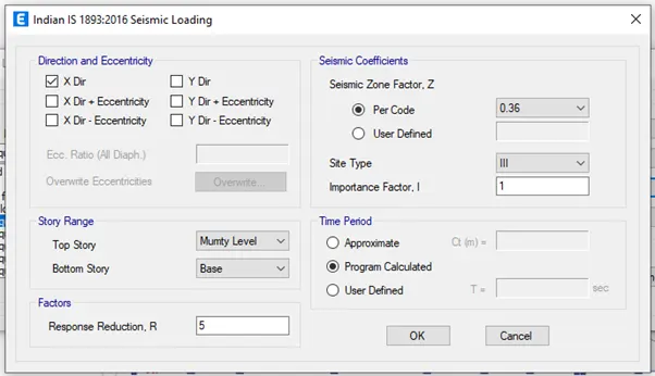
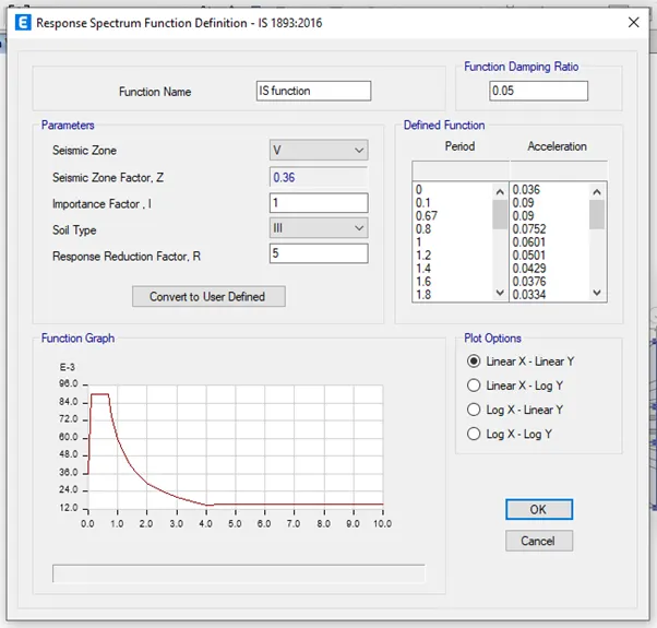
Click on modify lateral load of all earthquake loads, set a range from base to mumty floor, seismic zone factor as 0.36, importance factor as 1, site type as III and time period as program calculated
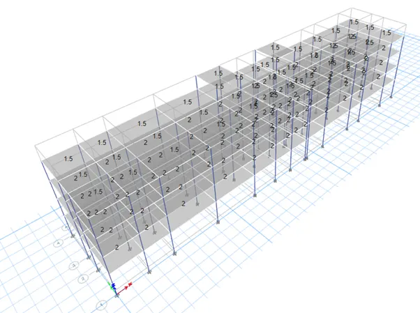
Step 8 : Assign live load and floor finish to all the story
Give the live load as 2KN/msq for all the stories
By selecting the slabs go to assign tab and select shell load and do the settings accordingly and click apply
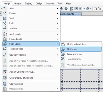
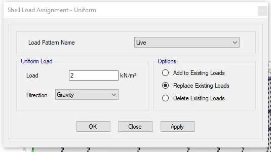
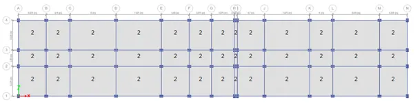
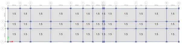
Step 9 : Assign wall load to all the story
Give the brick wall load as 3.5KN/m for all the stories
By selecting the beams go to assign tab and select frame load and do the settings accordingly and click apply
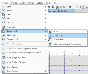
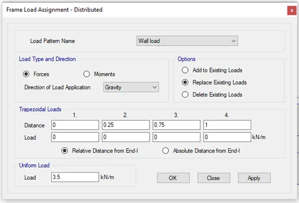
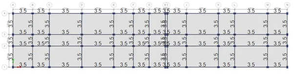
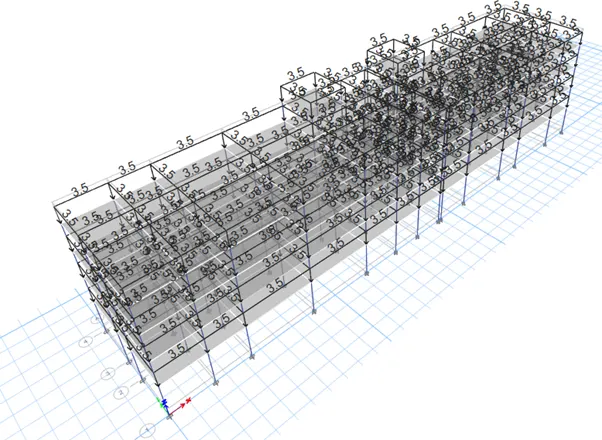
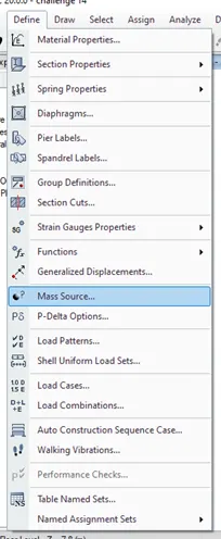
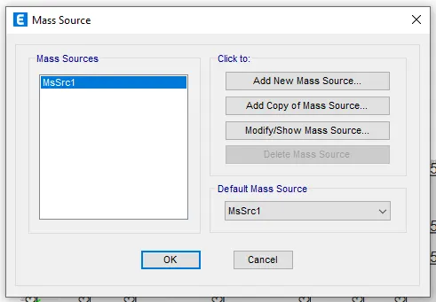
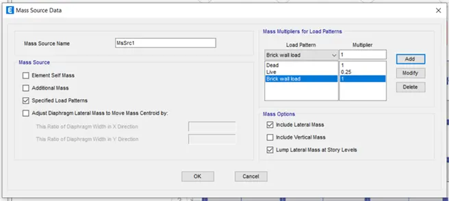
Step 10 : Go to define tab and select mass source and modify the mass source
Add the required load and assign the load to the model
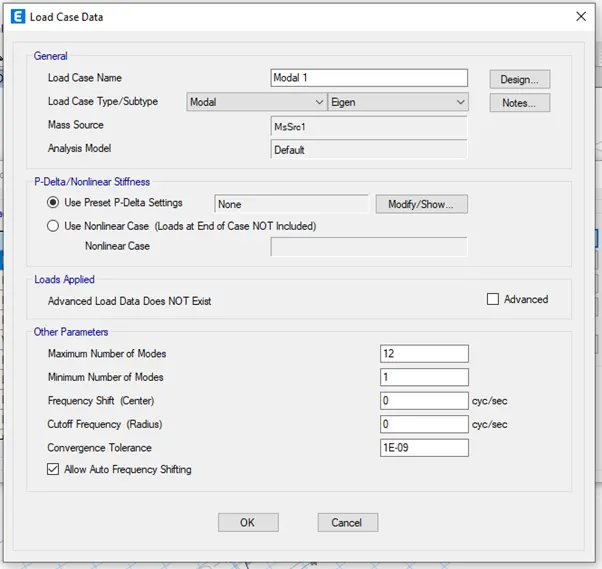
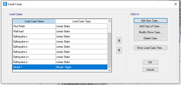
Go to define tab in that select load combination and add new modal case 1
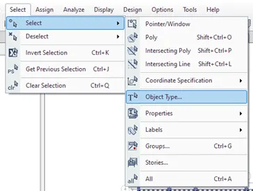
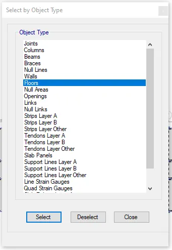
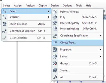
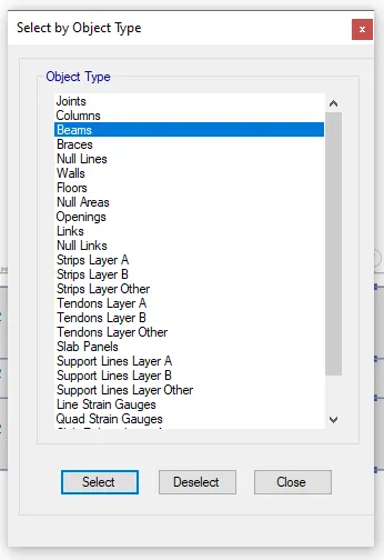
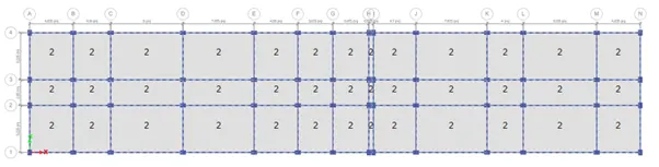
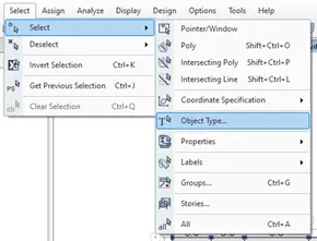
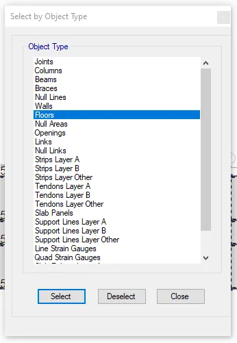
Step 11 : To create the diaphragm to the shell go to select in that select object type and in that select floors and click select and press close
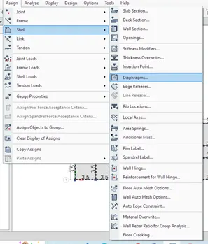
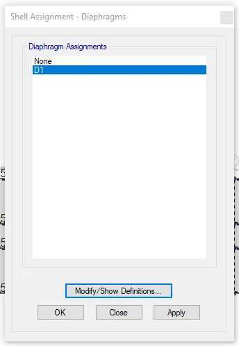
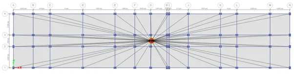
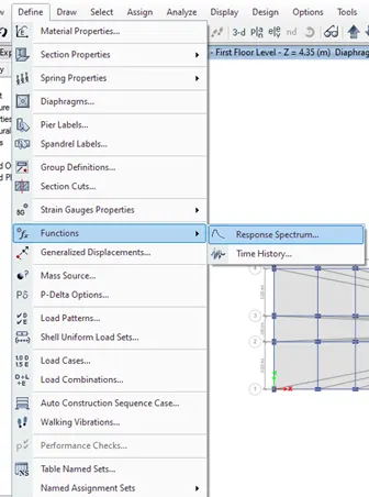
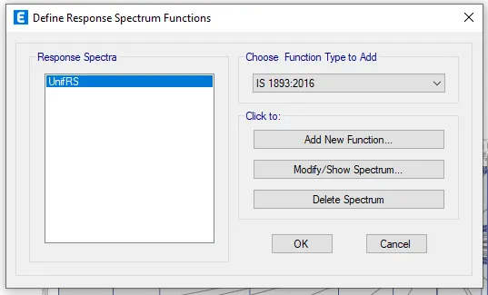
Step 12 : Go to define tab select functions in that select response spectrum
After selecting response spectrum a new dialogue box will appear in that choose IS 1893 – 2016 in choose function type and click on modify/show spectrum
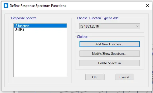
A new dialogue will appear in that give function name as IS Function and remaining details same as per the code so no need to change
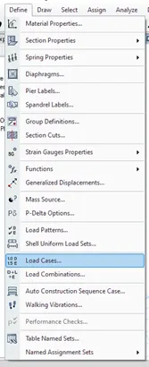
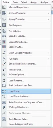
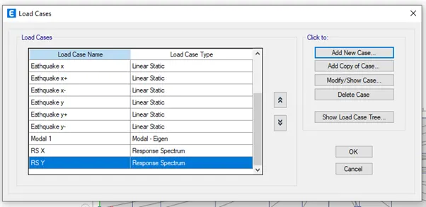
Step 13 : Go to define tab in that select load cases
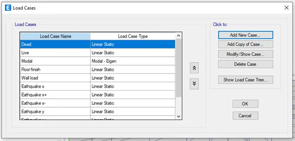
In the dialogue box appeared select add new load cases and add the required load cases
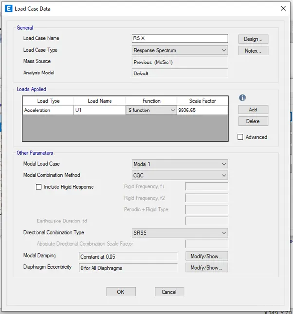
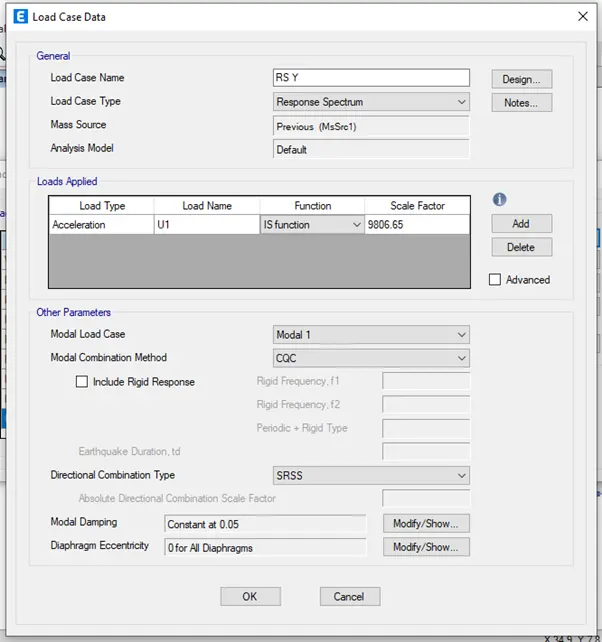
Add detail of load case in the load case data
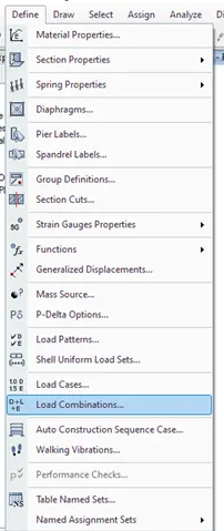
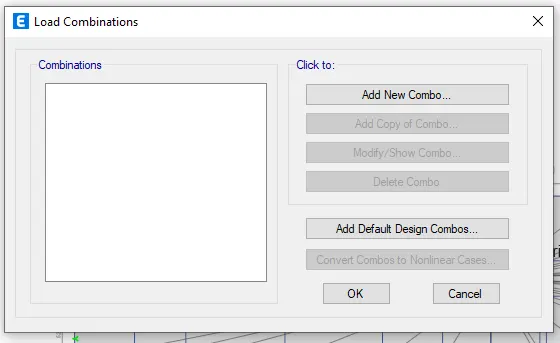
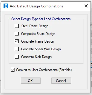
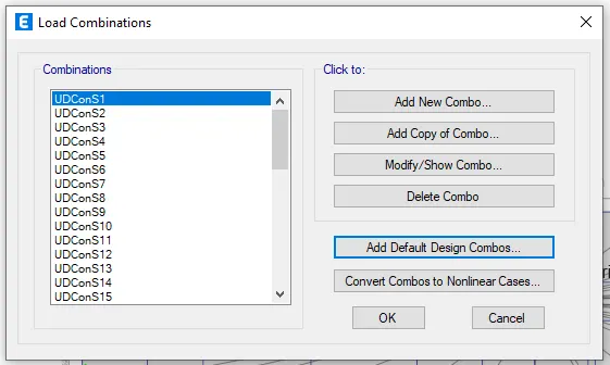
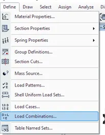
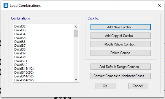
Step 14 : Go to define tab and select load combinations in the dialogue box click on add default design combinations in the dialogue box select Concrete frame design and click ok
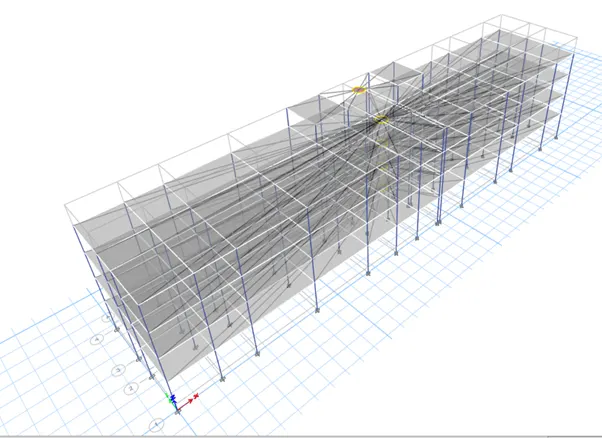
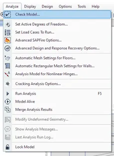
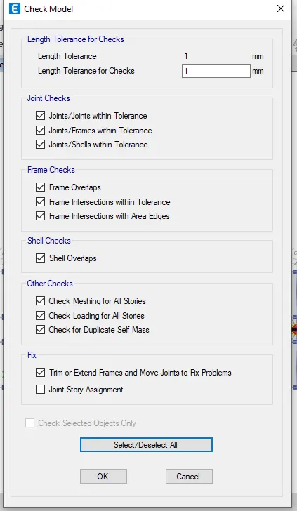
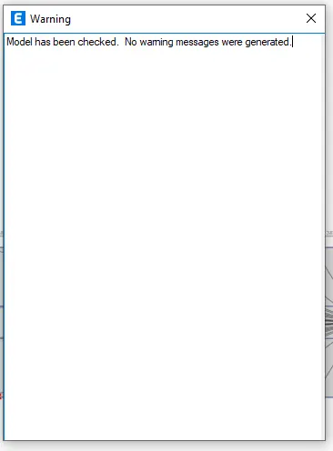
Step 15 : Go to Analyze and select check model and analyze the model for errors
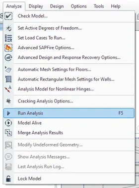
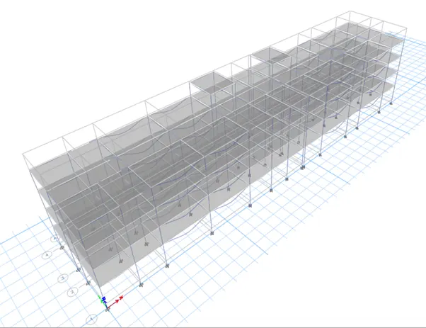
Step 16 : Go to analyze tab in that select run analysis the model will get analyzed and results will occur
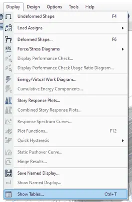
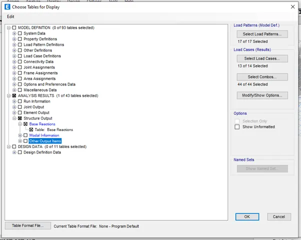
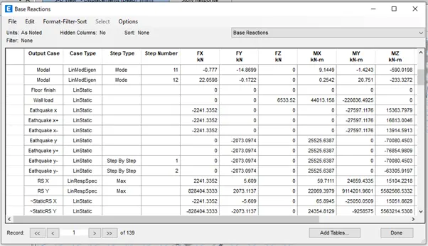
Step 17 : Go to display tab select show tables and select base reactions and click ok
Base reaction table as been appeared
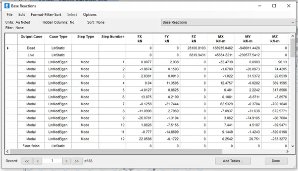
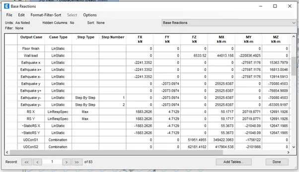
Now we have to check EQ should be closer to RS, So we have to calculate in both x and y direction
(EQ / RS) x scale factor of response spectrum
(2241.3352/1883.2626)x9806.65 = 11671.2294 KN in x direction
(2073.0974/4.7129)x9806.65 = 4313722.043 KN in y direction
Put the above values as scale factor for response spectrum at both x and y direction in the load case data
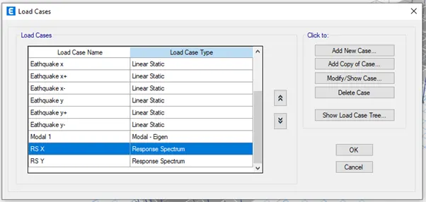

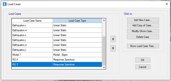
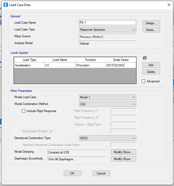
Again run the analysis and then again select base reaction table the EQ is closer to RS
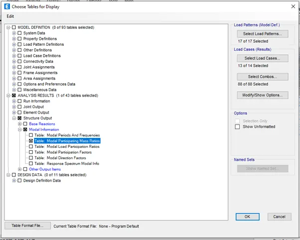
Step 18 : Go to display tab select show tables and select modal participating mass ratio and press ok
Modal participating mass ratio table as been appeared
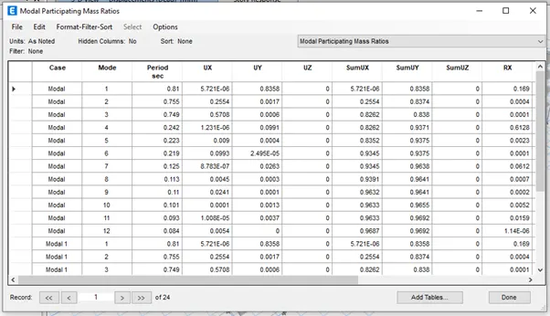
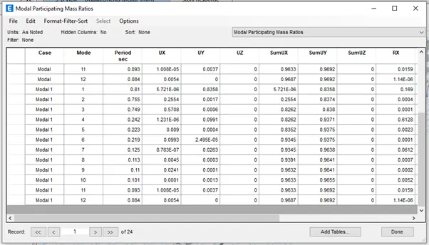
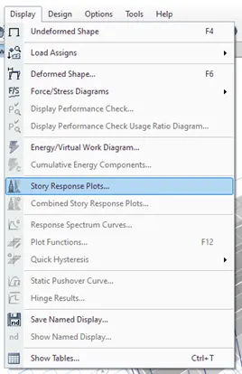
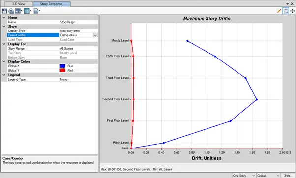
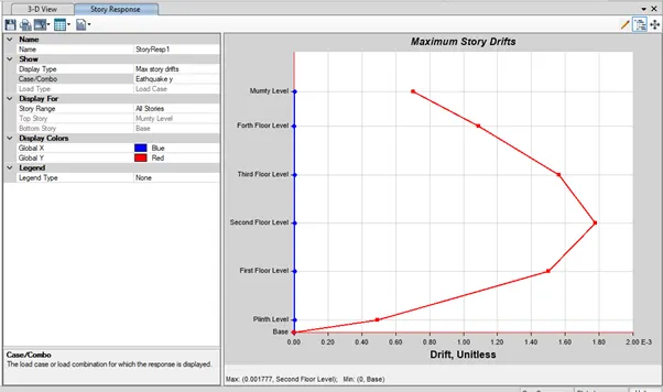
Step 19 : Go to display select and select story response spectrum and select story response as maximum story drifts in both x and y direction and it should be not more than 4%
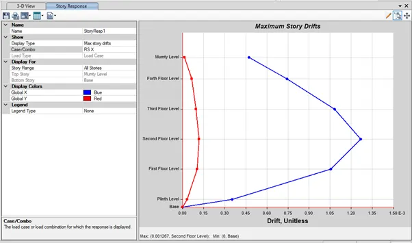
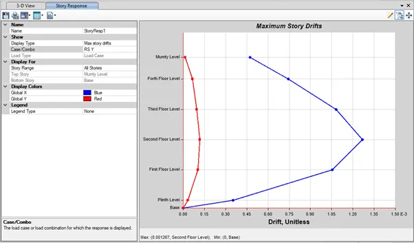
Step 20 : Go to concrete frame design and run
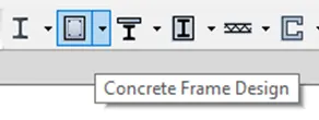
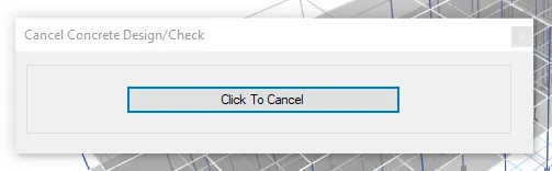
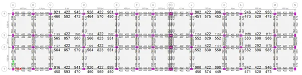
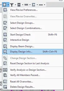
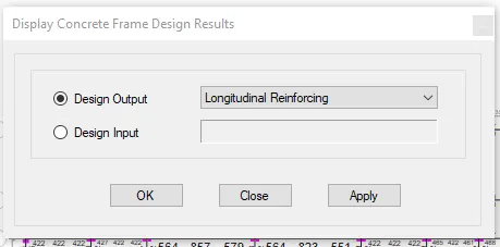
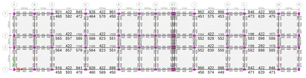
After the run drop down the arrow next to concrete frame design and select display design info I that select longitudinal reinforcing and shear reinforcing
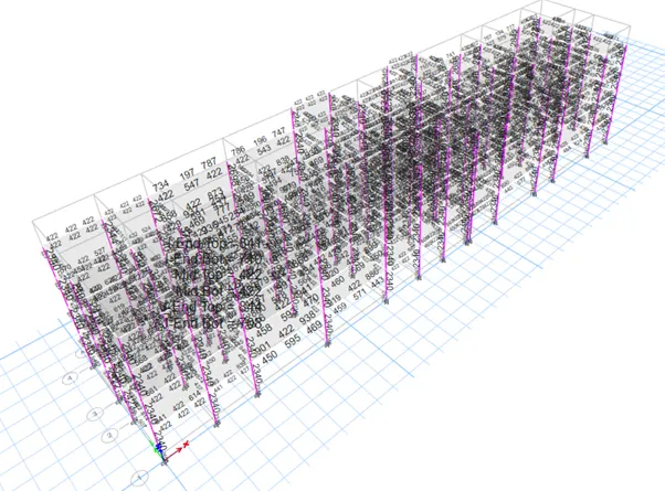
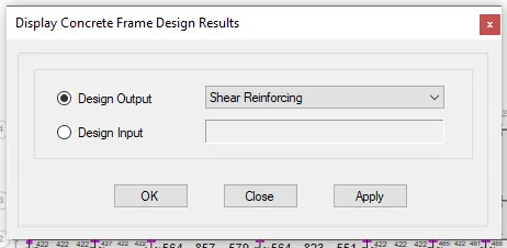
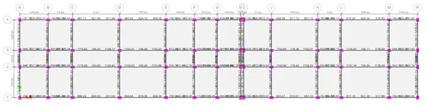
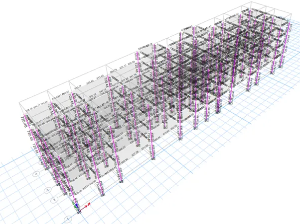
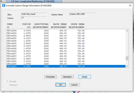
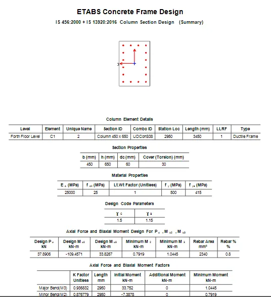
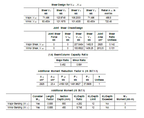
Step 21 : Now go to plan view and select base
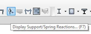
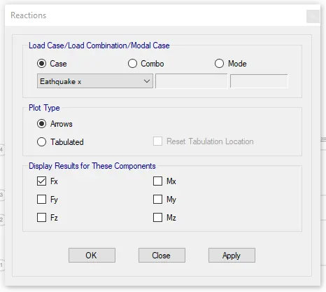
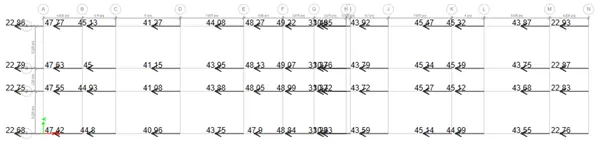
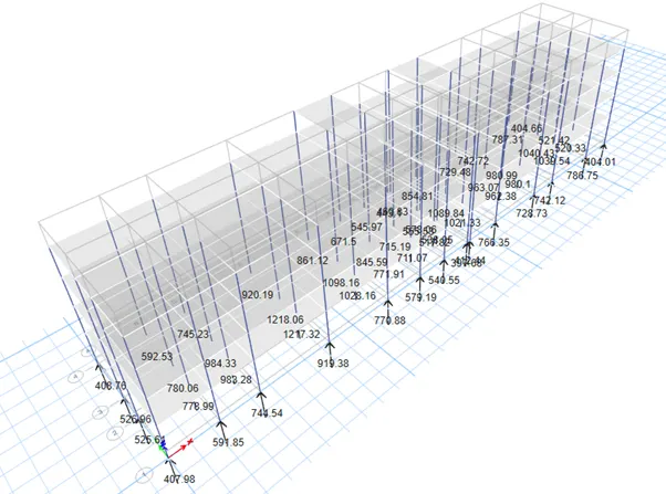
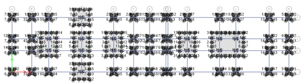
select reactions tab and select earthquake load toward x direction in the load case and click ok. Now base shear reaction will appear
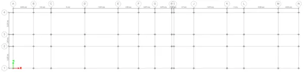
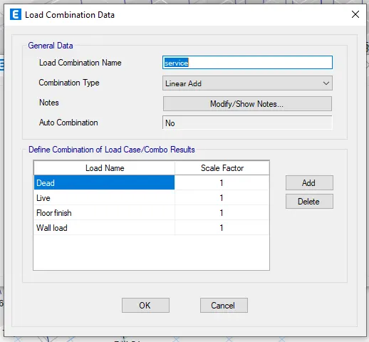
Step 22 : Go to load combination and add service load go to reactions select load combo as service and apply you will get the lad acting on the column in z direction
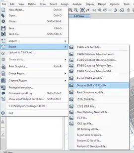
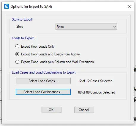
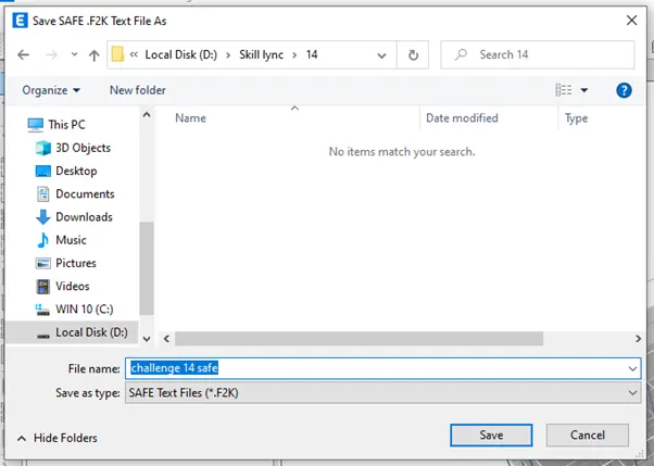
Step 23 : Go to file tab select export in that select safe software file version and save the file accordingly
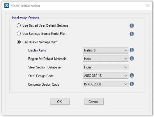
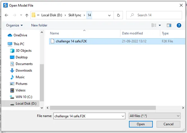
Step 24 : Open the safe software and import the file exported from etabs
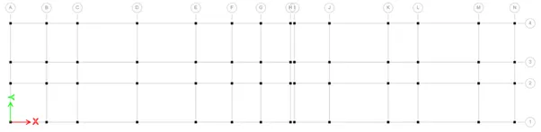
Given data
Column size - 450 x 600 mm
Soil type – III
Length of the pile – 10 m
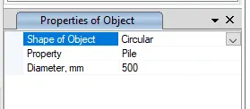
Pile diameter – 500 mm
Load carrying capacity of the pile – 280 KN
Soil bearing capacity – 150 KN/sqm
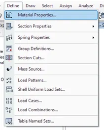
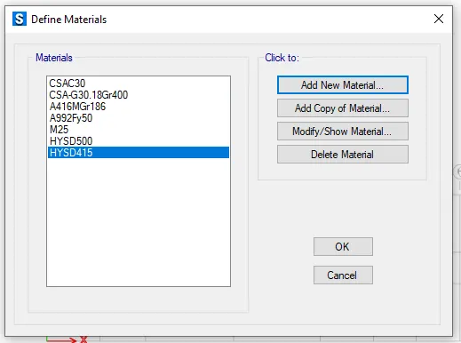
Step 25 : Go to Define tab in that select material properties in that add new material property and add required material
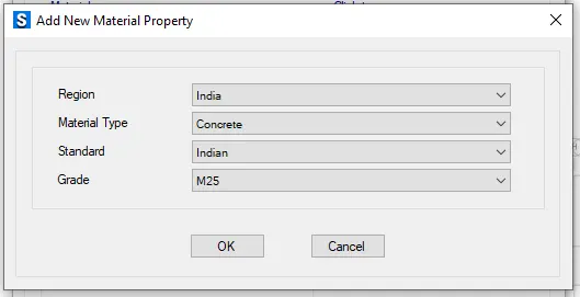
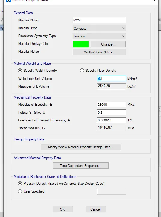
Material property data :
Click define followed by material properties
M25 grade of concrete

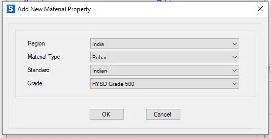
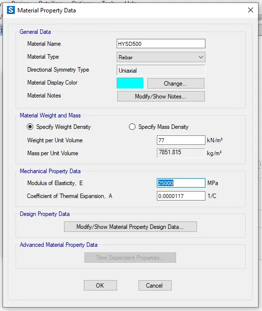
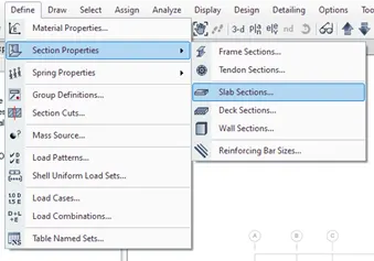
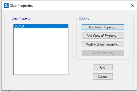
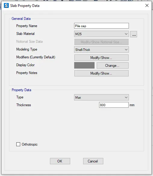
Step 26 : Go to define tab in that select section properties and select slab sections
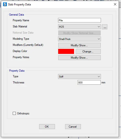
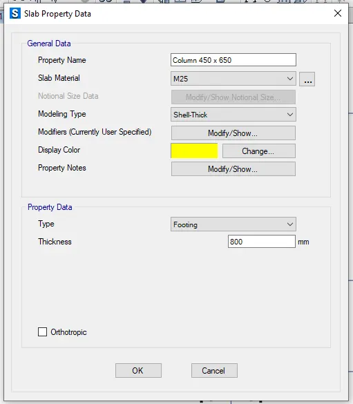
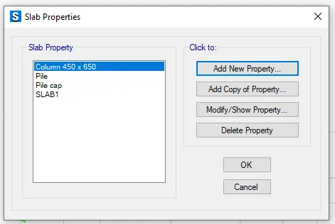
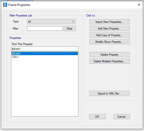
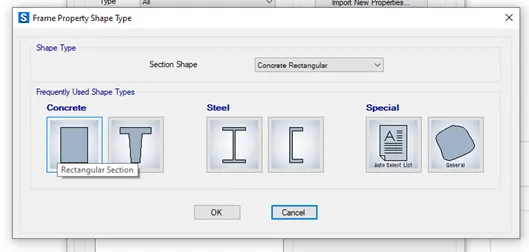
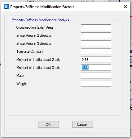
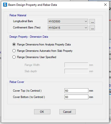
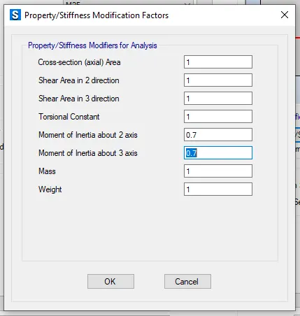
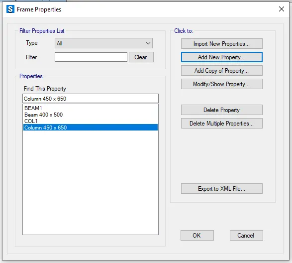
Step 27 : Go to define tab in that select section properties and select frame sections
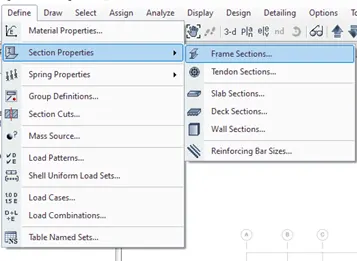
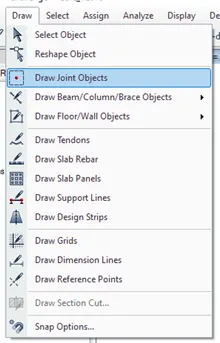
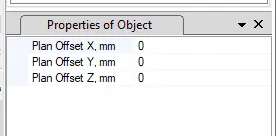
Step 28 : To draw the slab first we need to go to draw ta in that select draw point object and draw the points accordingly
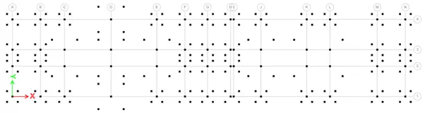
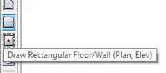
Select draw rectangular floor and draw the slab by using points created
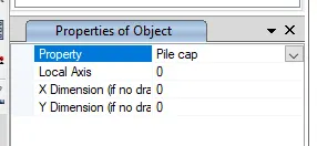
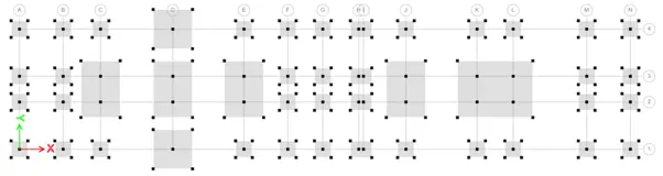
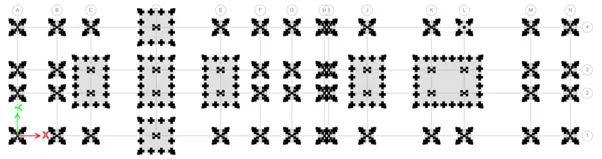
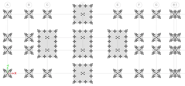
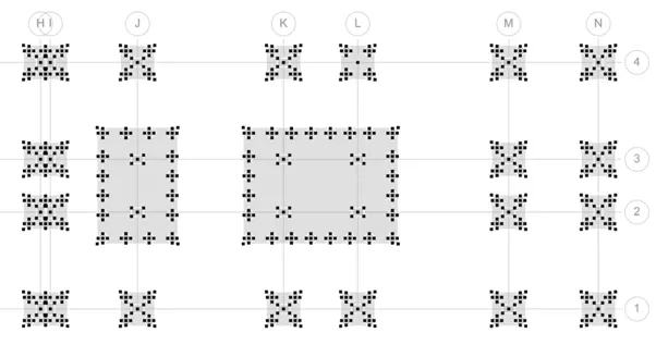
Step 29 : Draw the points by using draw joint objects and draw the points to place the piles
Draw the pile at the points created by using quick draw area around points
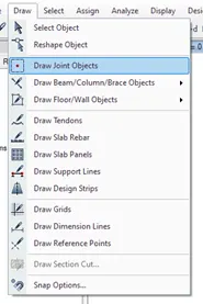
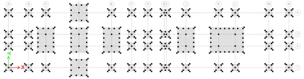
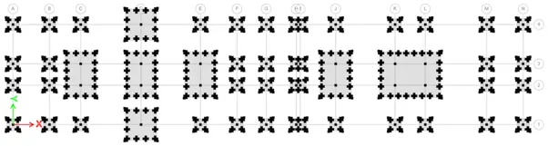
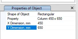
To draw a rectangular column draw the point at the middle and draw the column of size 450 x 650 mm and 650 x 450mm
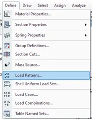
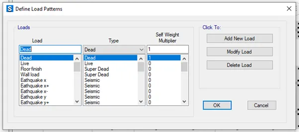
Step 30 : Go to define tab and select load pattern
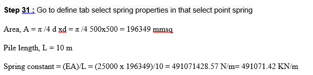
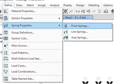
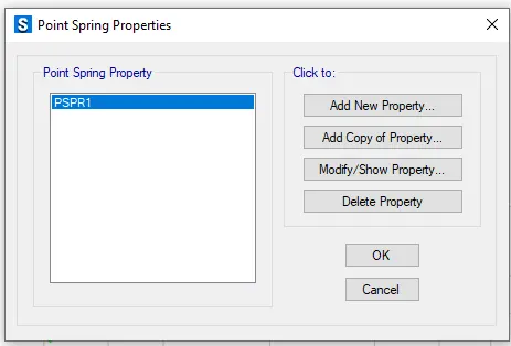
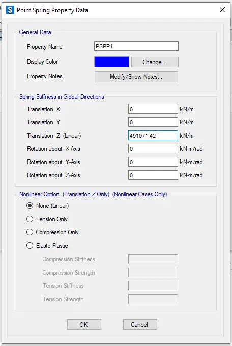
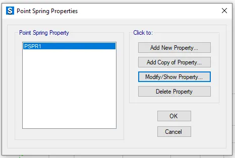
Assign the spring load to the pile
Go to assign tab select the joints in that select point and assign the point spring load to the pile selected
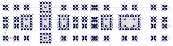
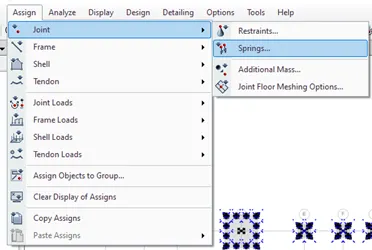
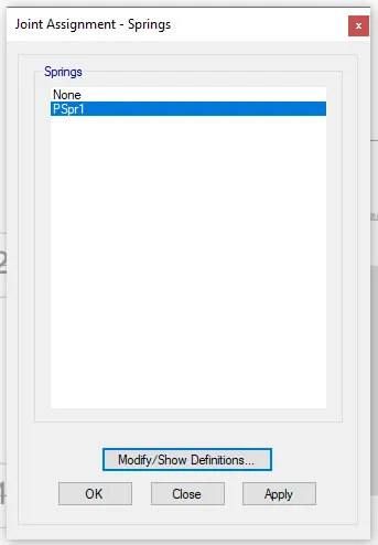
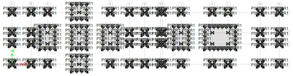
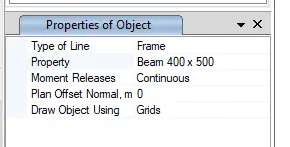
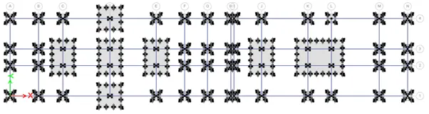
Step 32 : select Quick draw beams and draw the beams on the grids
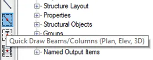
Step 33 : Go to define tab select load combinations and check
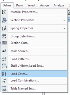
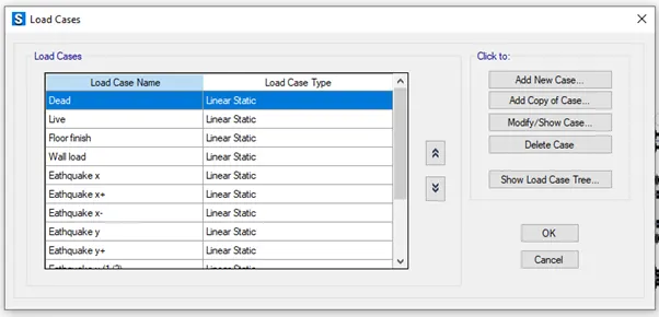
Step 34 : Go to define tab select load cases and check
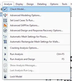
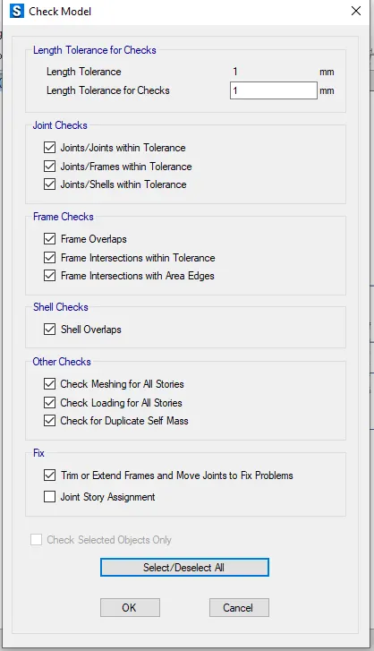
Step 35 : Go to analyze tab and select check model for errors
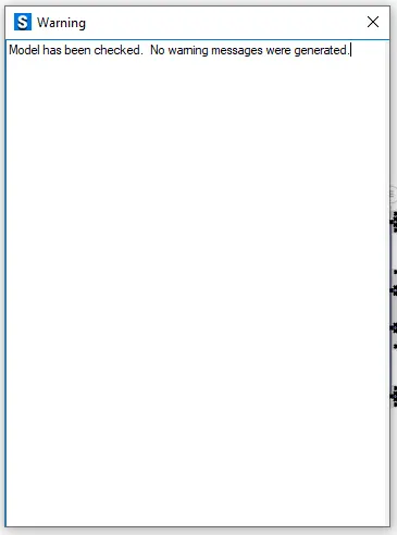
Step 36: Run the analysis
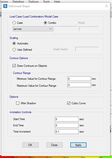
Deformed shape
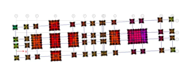
Punching shear
RESULT : The given challenge is completedby using Etabs and Safe software