Project 2_Design & Analysis of a Hostel building at Guwahati, Assam
In this project, participants will get to experience the entire design process from modelling, analysis, design, and preparation of construction drawings. The architectural drawings of a G+3 RCC building are provided. The following information on the building is to be used:
Location – Guwahati, Assam
Function – Hostel block in an academic institute
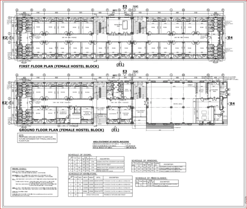
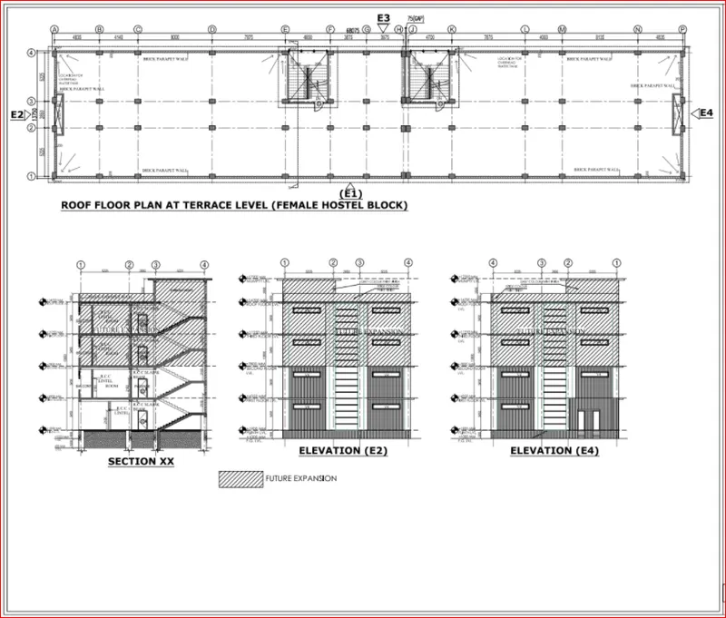
The walls will be made of AAC blocks. Other loadings are to be calculated as per the architectural drawings.
The buildings rest on type 3 soil. Piles of length 10 meters and 500 mm in diameter with a load-carrying capacity of 280kN are to be used.
The ground floor level will be at a height of 2 meters above the existing site level to avoid floodwater entering the building.
M25 grade of concrete with Fe500 for longitudinal reinforcement and Fe 415 for shear reinforcement is to be used.
The following design IS codes will be required for reference:
- IS 875 part 1
- IS 875 part 2
- IS 13920
- IS 1893
- IS 2911 part 2
- IS 456
- SP 34
Students will have to produce the following:
- ETABS model for the two blocks on either side of the expansion gap
- Foundation details illustrating the pile & pile cap reinforcement
- Tie beam details connecting the pile caps
- Column reinforcement
- Framing plan for typical floor
- Beam reinforcements for ground floor
AIM
- To Model, analyse, design, and prepare the construction drawings from the provided architectural drawing of a G+3 Hostel building.
- To design foundation detail illustrating the pile and pile cap reinforcement, Tie Beam details connecting the pile caps, Column reinforcement, framing plan for the typical floor, and Beam reinforcements for the ground floor.
INTRODUCTION
Computational analysis and design of multi-storey buildings have become a lot easier with the use of modern software tools like ETABS. The software helps fasten the design process and assists from the very first phase of modelling till the detailing process. At the same time, the accuracy and precision achieved through these computational tools are unmatched. However, you must know the manual concepts that run behind any building analysis model. So, the right conceptual knowledge in addition to hands-on tool experience is what is needed to execute any project successfully from start to end. And this is what is done in this project. A 3-story hostel building has been modelled, analysed, designed, and detailed to send the good for construction drawings at the site.
The procedure for analysis and design of a given building will depend on the type of building, its complexity, the number of stories, etc. First, the architectural drawings of the building are studied, the structural system is finalized, and the sizes of structural members are decided and brought to the knowledge of the concerned architect. The following information of data is required before starting the structural design:
A set of architectural drawings;
Soil Investigation Report;
Location of the place or city to decide on wind and seismic loadings;
Data for lifts, water tank capacities on top, special roof features or loadings etc.
PROCEDURE
The Architectural plan and the sectional elevation of the building to be modelled and analysed using ETABS have been provided.
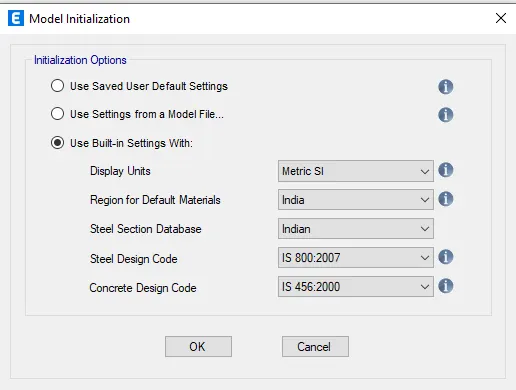
Open the ETABS software and specify the codes and specifications to be followed for the project.
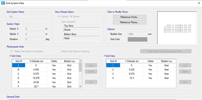
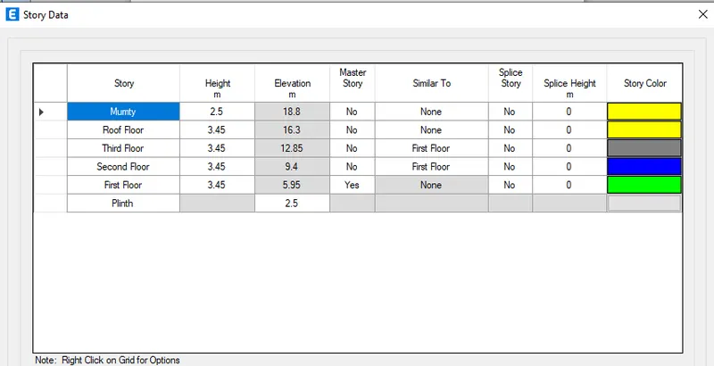
Specify the grid and the storey data as per the given Architectural drawings.
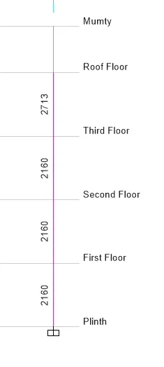
Specify the height of each floor, set the First floor as the master story and all other floors similar to the first floor.
Click on Define Tab>material properties
Click on add new material
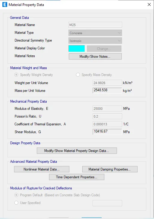
Add M25 grade concrete
Check material property data
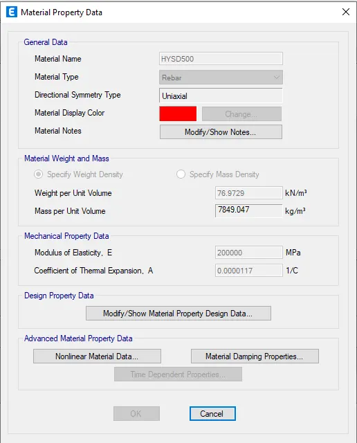
Add rebar Fe500
Check material property data of the HYSD bar
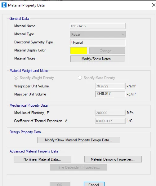
Add rebar Fe415
Check material property data of the HYSD bar
Go to define>section properties>frame sections
Click on Add new property
Select the rectangular concrete and click ok
Add new beam and column frames
Change the property name as per given data B300x450> change material to M25
Enter the depth and width of the sections
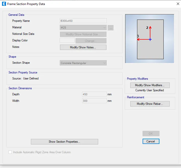
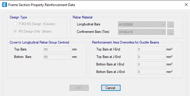
Click on Modify/show rebar>to enter the rebars types and numbers
Click on M3 design only
Change longitudinal bars to Fe500 and Tie bar types to Fe415
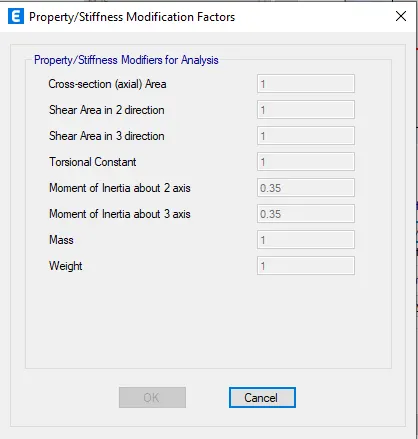
Click on property modifiers
Change the Moment of inertia about 2 axis and 3 axis to 0.35
Again on frame sections> Add new property
Select the rectangular concrete section> click on OK
Rename the property as C450x600
Enter the width and depth of the column
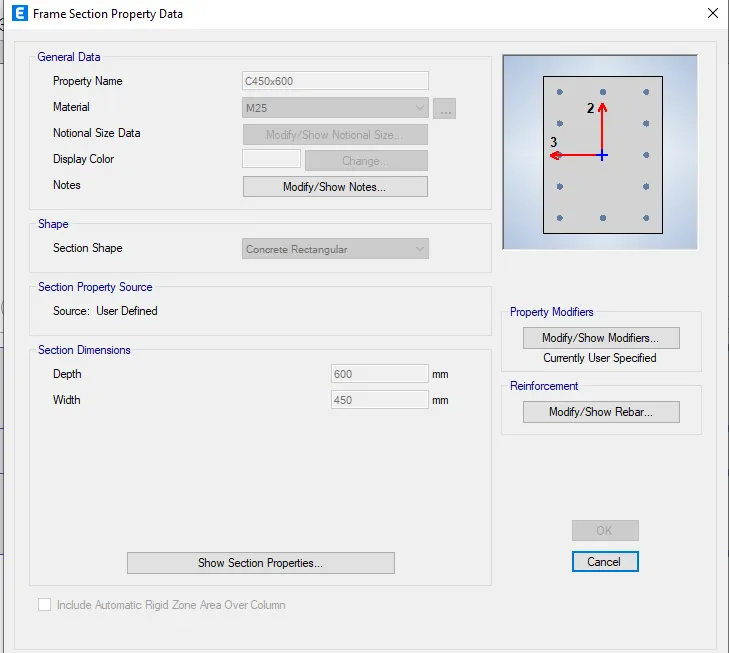
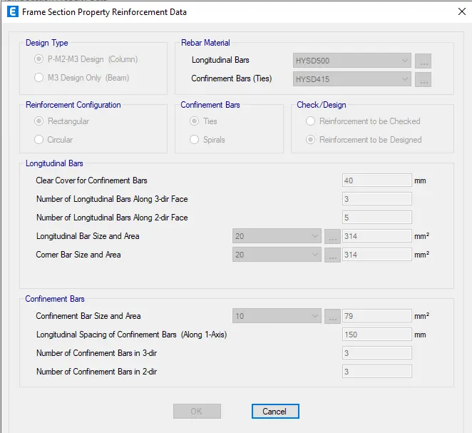
Click on modify/show rebar> to enter the bars type of columns
Click on P-M2-M3 design> Enter longitudinal and tie bars type
Reinforcement to be designed> Enter the number of bars required in 2&3 direction
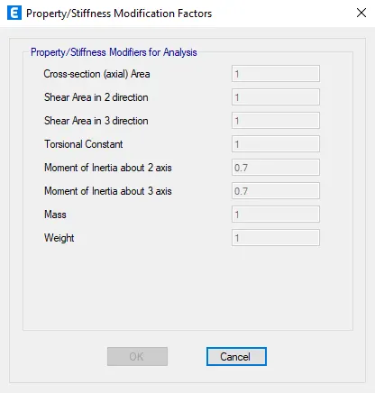
Click on property modifiers
Change the Moment of inertia about 2 axis and 3 axis to 0.7
Select slab section for the slab of 120mm
Go to define> section properties> slab sections
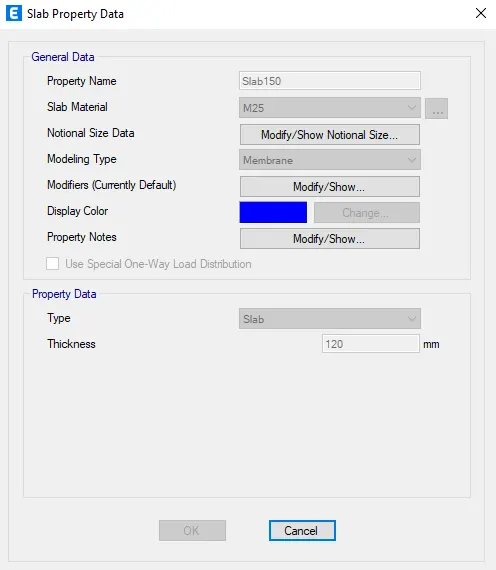
Click on slab1> modify/Show property
Rename the slab as Slab150
Select the slab material as M25> Modelling type as "membrane"
Enter the thickness of the slab
Again Go to define> section properties> slab sections
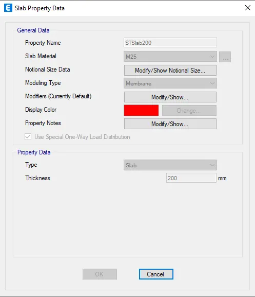
Add new property> Rename the slab as STSlab200
Select the slab material as M30> Modelling type as "membrane"
Enter the thickness of the slab and select “Use special one-way distribution”
Add columns to the structure.
Go to the bottom right corner and select ALL STORIES
Click on "Quick draw columns" on the left side toolbars
Select the C450x600 from the property
Select all the columns ->all the columns will be applied to the grids
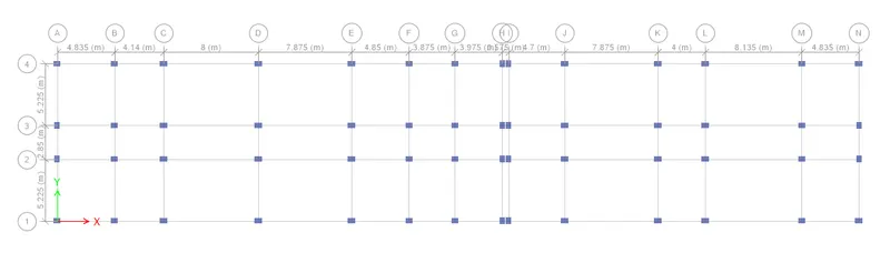
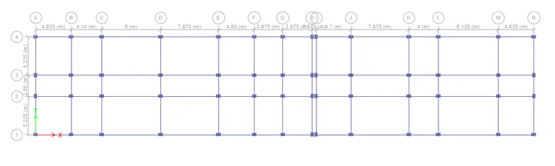
Select quick draw beams (keep the selection to ALL stories)
Select the property to B300x450
Select all the beams section> the beams will be applied
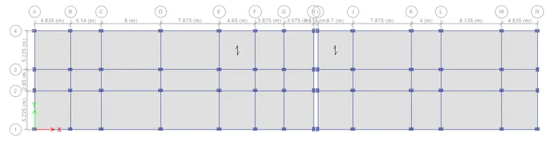
Now add slabs to the section> Select quick draw floors/Slabs
Change the property to slab 150
Change the selection to similar stories
Select all the slabs of any one floor
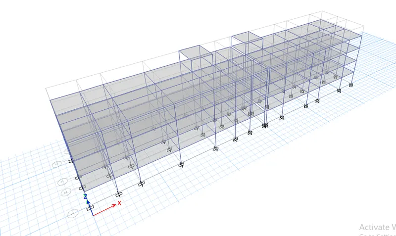
Now add joints to the base
Go to Assign bar> Joints> Restraints
Select the fixed joint
Now define load patterns
Go to Define Bar> Load patterns
Add dead load, live load, brick wall load, finishes and earthquake load
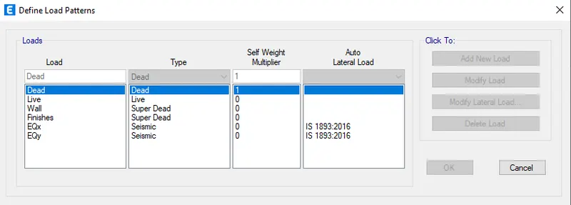
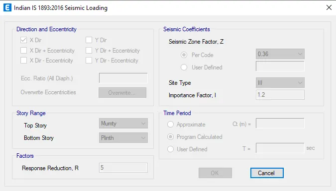
Click on earthquake loads "EQx" > Click on Modify lateral load
Select the Load direction (X dir)
Select Site III, seismic zone factor as 0.36 & time period as the program calculated
Do this for all the earthquake directions, just change the eccentricity and direction in the above
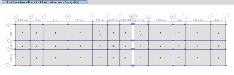
Assign the live load to the slabs and brick wall loads
Select all the slabs of any floor> Change the selection to similar stories
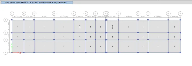
Go to Assign> Shell loads> Uniform
Apply the 3 kN/m2 live load for the staircase portion, veranda, and washroom area.
Apply the 2 kN/m2 live load for the remaining portions of the building.
Apply the 1 kN/m2 loa finishes for the entire building.
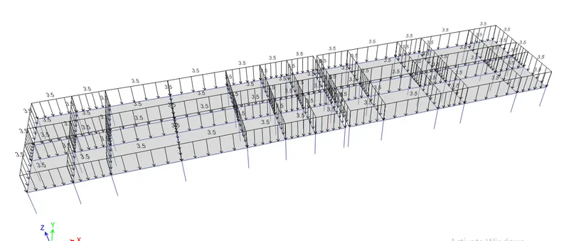
Assign the wall load to the beams
Go to select menu> object types> select beams (all beams will be selected)
Go to Assign menu> Frame load> distributed
Enter the value of 3.5kN/m
The value of 3.5 kN/m is derived from the density calculations as we are using AAC block as the masonry material.
Define mass source
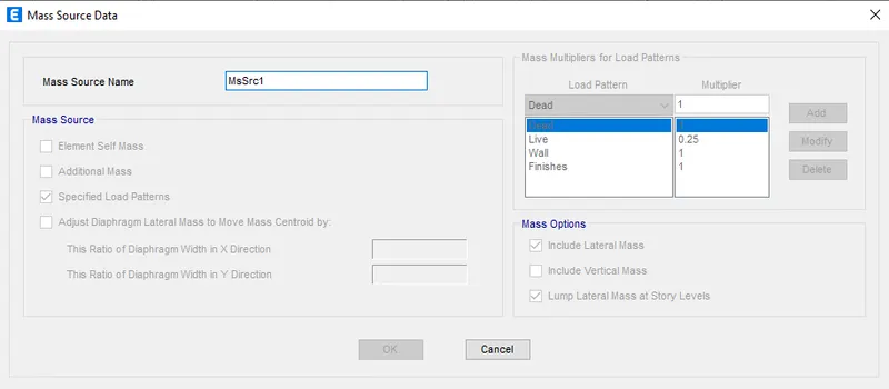
Go to Assign Menu> Mass source
Click on Modify/show mass source
Select specified load patterns
Input dead=1, finishes=1, brick wall=1, live=0.25
Making the diaphragm of the structure
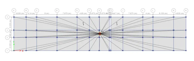
Go to select menu> object types> select the floors
Assign> Shell> Diaphragm
Select D1 and apply
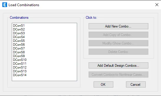
Go to define menu> load combination
Click on Add default design combos
Select concrete frame design
Check the model for errors
Go to analyse menu> check model
Go to analyse menu> run analysis
Structural Output Checks
Modal Participation Ratio Check
Go to model explorer> Tables> Analysis Result> Structure Output> Model Information> Modal Participation Mass ratio
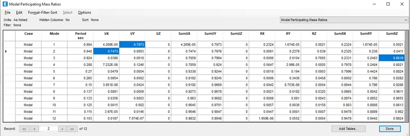
As per IS 1893:2016 clause 7.1
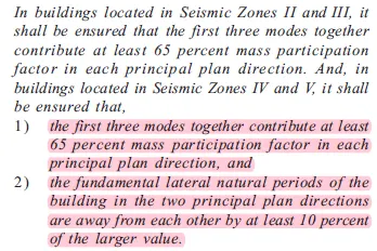
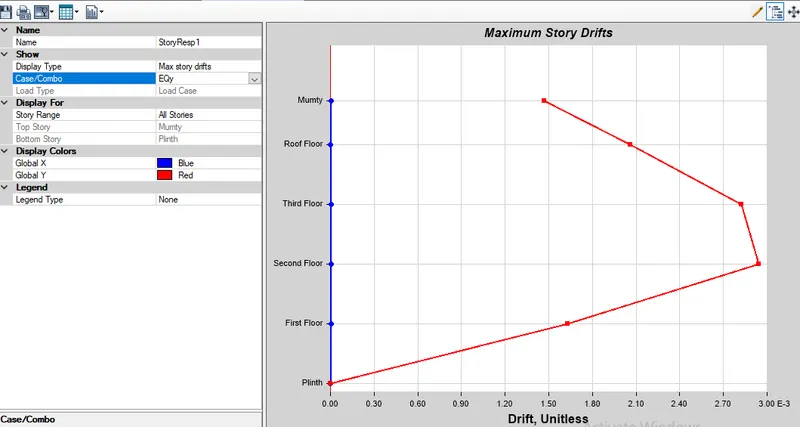
Check for the Inter-Story Drift
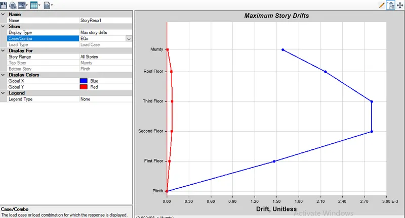
Go to Display> Story Response Plots
Select maximum story drifts
Check for EQx and EQy
According to IS 1896:2016,
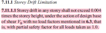
Story Drift in the X-direction
Story Drift in the Y-direction
Check for axial load ratio
As per IS 13920
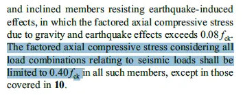
Therefore the maximum axial load should be
0.4 fck c.s.a. x grade of concrete
0.4 x 450x 600 x 25 /1000
2700kN
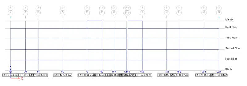
Checking each column for this maximum load. The maximum load is 1776kN.
Hence OK.
Designing of the frame sections
Go to Design> Concrete Frame Design> View/Revise Design References
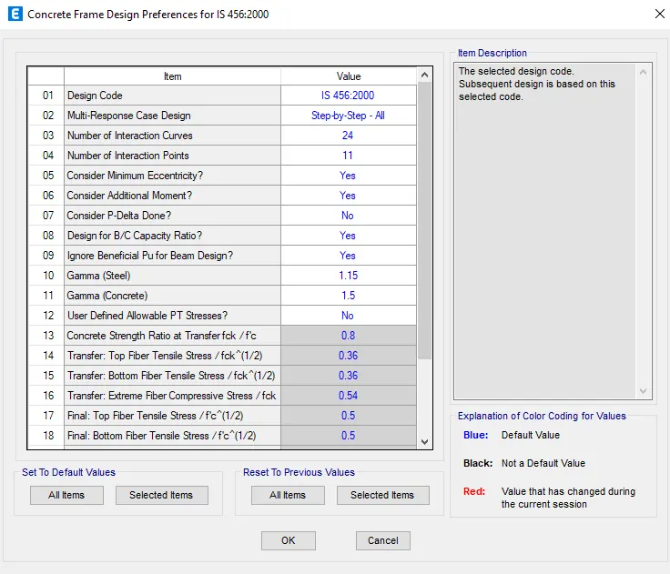
Design > Concrete Frame Design> Select Design combination
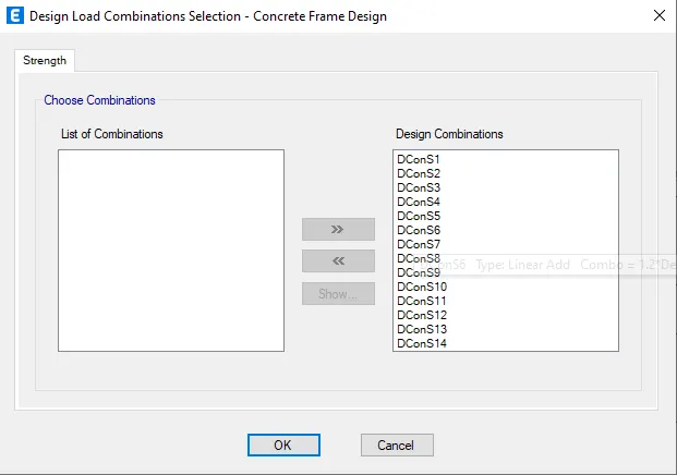
Design > Concrete Frame Design> Start design/check
The ETABS model is analysed and designed as per IS 456:2000 in ETABS as shown below.
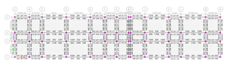
Design > Concrete Frame Design> Verify all members passed
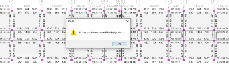
Design > Concrete Frame Design> Display design info > Total Longitudinal reinforcement
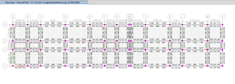
Design > Concrete Frame Design> Display design info > Shear reinforcement
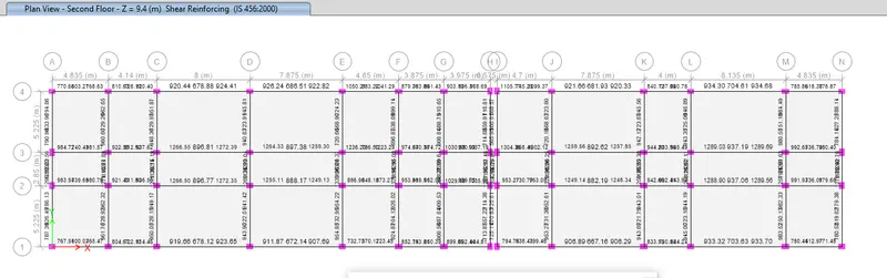
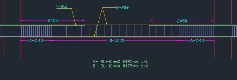
Once the analysis is complete the detailing of a typical beam is drawn as shown below according to the steel provided.
Reinforcement detailing of the concrete frame using AutoCAD.
Beam Longitudinal Steel Requirements
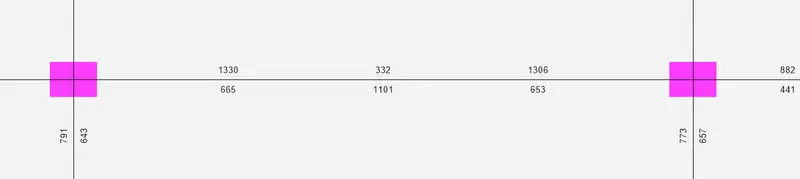
B34 Shear Steel Requirements

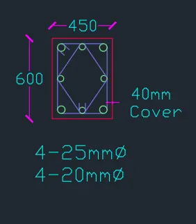
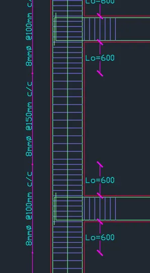
Reinforcement Detailing as per IS-13920
Column Longitudinal Steel Requirements
Shear Requirements
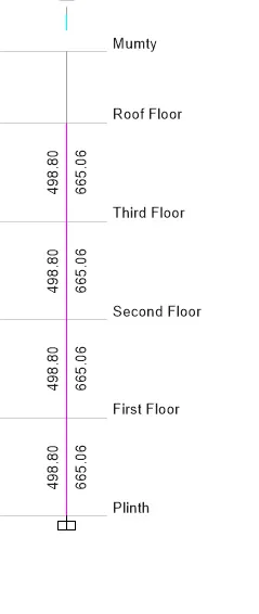
Reinforcement Detailing As per the IS-13920
Foundation Design Using SAFE
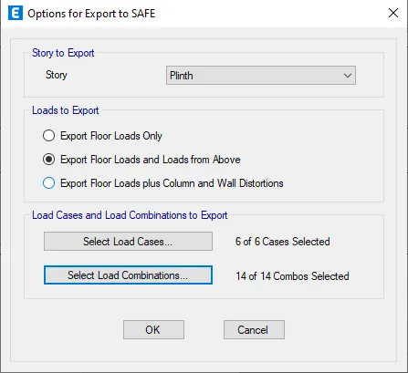
To export the base floor loads and loads from above to the SAFE go to File> Export> Story as SAFE V12 .f2k File
Export the file as shown below
Open SAFE
Go to File> Import> SAFE .f2k text File
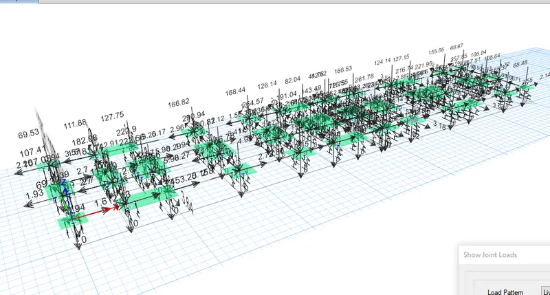
Go to Display> Show Loads Assigns> Joints
Select dead above and live above the values will be appeared
GIVEN DATA
Column size: 450 x 600 m2
Length of the Pile: 10 m.
Diameter of the pile: 500 mm.
Pile Bearing Capacity: 280 kN.
PROCEDURE
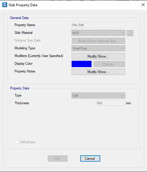
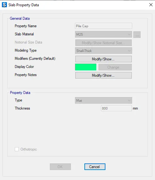
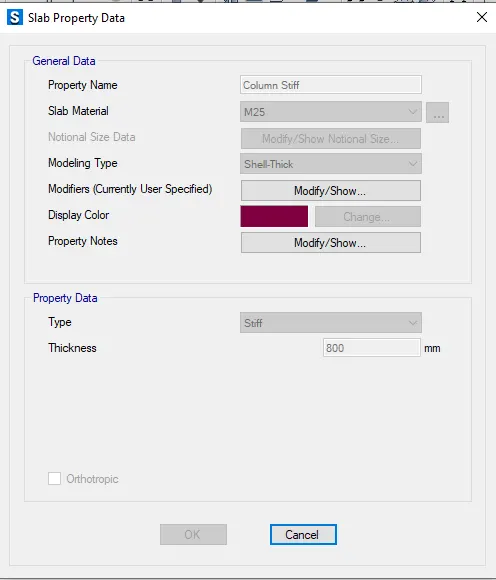
Go to Define> Section Properties> Slab Section> Add New Property
Add Pile Cap, Column Stiff and Pile Stiff with the following properties
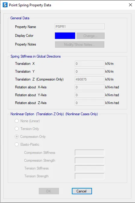
Go to Define> Spring properties> Point spring> Add New Property
Add PSpr1 with the following properties
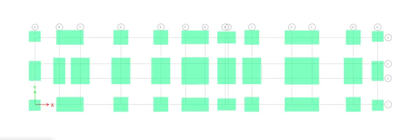
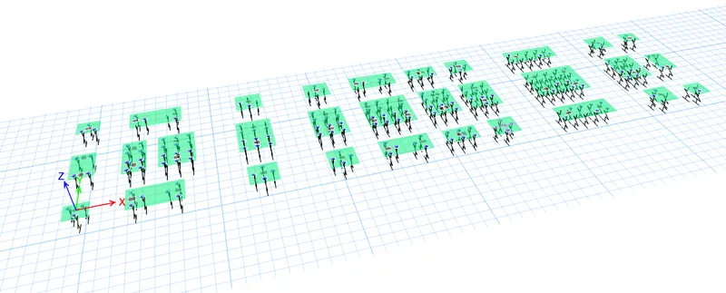
Draw a Rectangular floor of appropriate dimensions with the property as “Pile cap” around the column joints
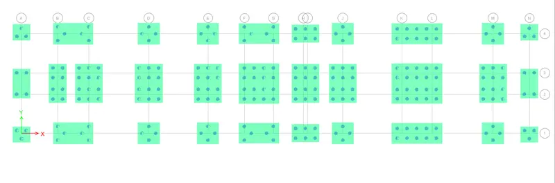
Select “Quick Draw Area around point”
Draw Piles with the property as “Pile500” at appropriate positions
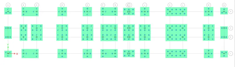
Select “Quick Draw Area around point”
Draw column with the property as “Column” at the centre
Select all joints of Pile Sttiff and assign point spring
Go to Assign> Joint> Springs
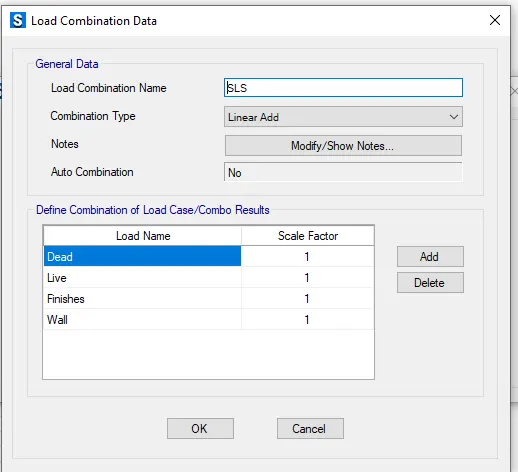
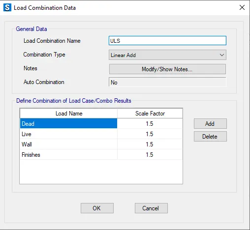
Go to Define> Load Combination> Add New Combo
Add SLS and ULS as shown below
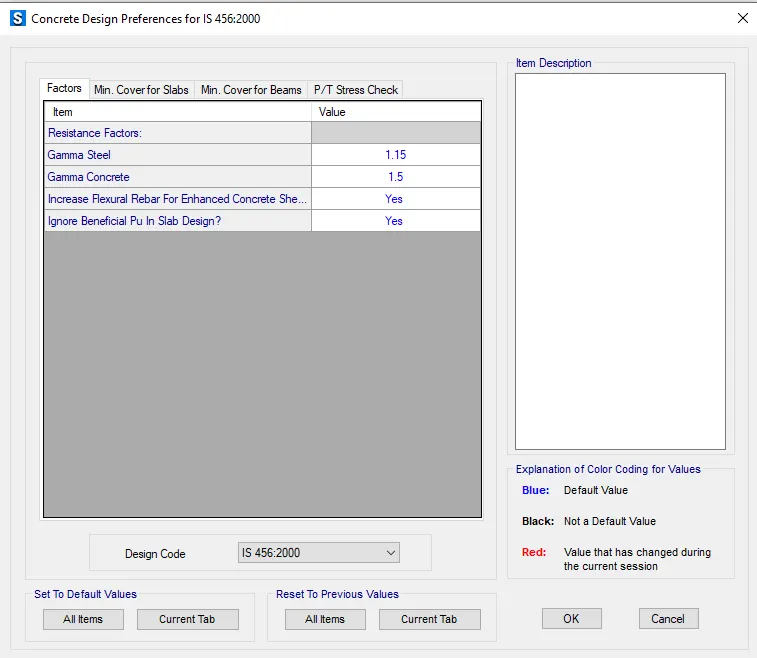
Go to Design> Concrete Slab/ Beam Design> View/ Revise Preferences
Check design preference
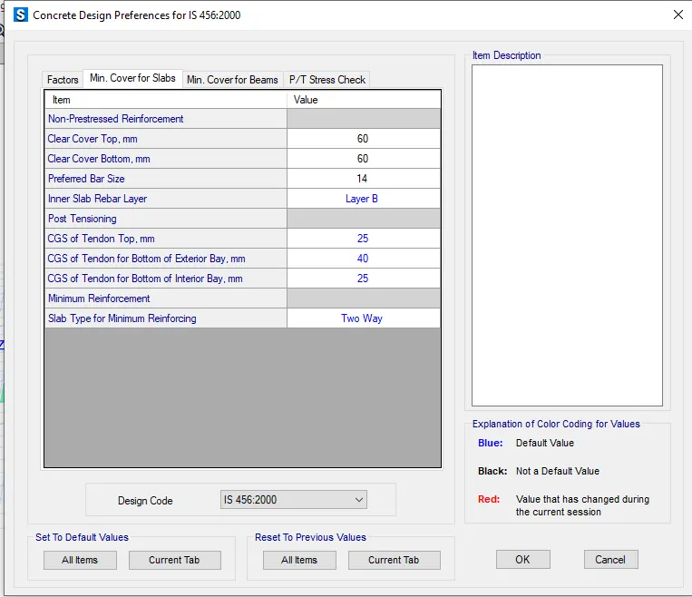
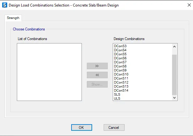
Go to Design> Concrete Slab/ Beam Design> Select design combination
Go to Analyse> Check Model
Run Analysis and Design
Check for Settlement
Go to Display> Show Deformed Shape
Check SLS combo
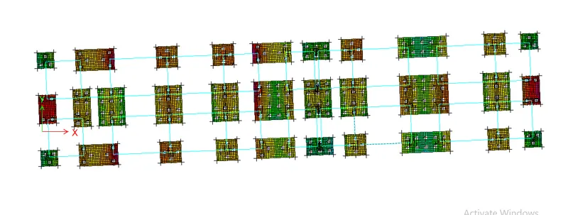
The settlement is 0.4mm is lesser than the permissible value stated by the codes (25mm). Hence OK.
Punching Shear Check
Go to Display> Show Punching Shear Design
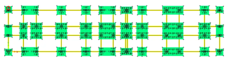
Here it is less than 1. Hence OK.
Base Reactions at Piles
Go to Display> Show Force/ Stress Diagrams> Support/ Spring Reactions
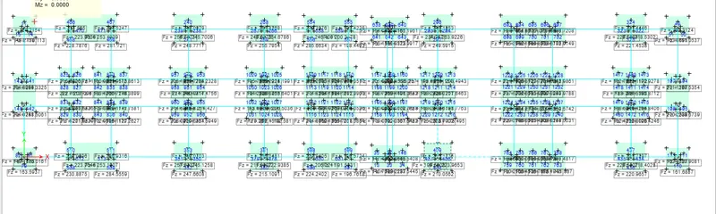
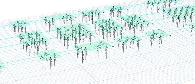
The pile capacity is 280kN. Hence OK.
Longitudinal Reinforcement Requirement
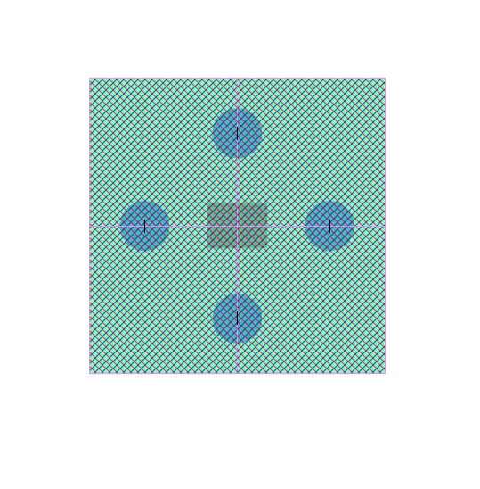
For reinforcement requirements, design strips are needed to be created
Go to Draw> Draw design strips
Provide the design strips as shown below
Run analysis
Go to Display> Show Slab Design
Maximum Rebar Area for the Strip A
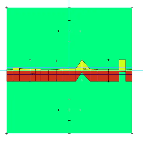
Maximum Rebar Area for the Strip B
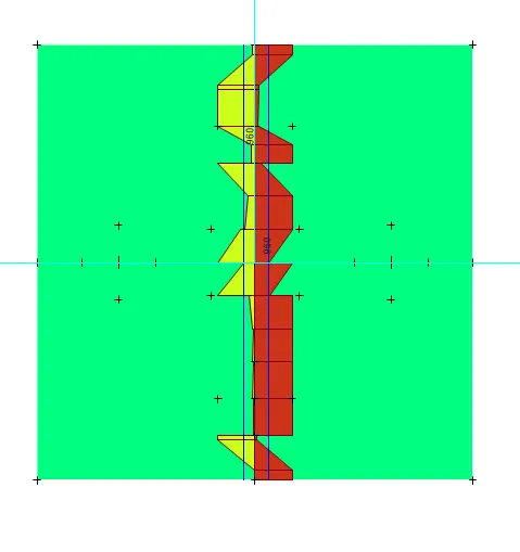
Reinforcement Bars Placement Plan
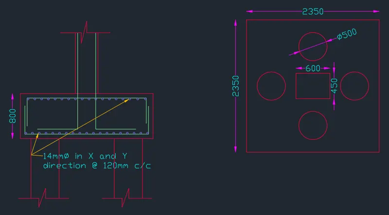
Section and Plan of the Pile Cap
RESULT
Analysis and design of high rise buildings using ETABS and foundation design using SAFE for seismic loads are completed using the relevant codes of practice and the outputs are attached here using AutoCAD software.