Project 2_Creating a 3D rendered model for a Residential Building in AutoCad
Create a 3 dimensional model of the residential building with a rendered view
AIM:
To create a 3 dimensional model of the residential building with a rendered view using AutoCAD software and explain the procedure step by step to obtain the result.
INTRODUCTION:
AutoCAD is a computer aided design software and drafting software application.
In this project, i have used important commands and settings like,
* 3D Basics and 3D Modelling setup
* Line, 3Polyline, Polysolid - to create objects, walls.
* Layers - to assign objects and differentiate the drawing.
* Region, Boundary - to create regions.
* Extrude - to extend the object created.
* Subtract - to subtract objects.
* SWEEP - to create the hand railing.
* Material Browser - to assign different materials to objects.
* RR (Rendering) - To render the 3D drawing.
* Camera - to insert camera and view from cam angle.
* Lights - Distant lights were used in this project.
* Block - to create window blocks.
* Hide - to hide the extra wireframes and visualize a 3D model.
* UCS - To change the plane and work easily.
* various view types like Hidden, Shade, Isometric etc.. are used.
In the next step, the procedure is explained perfectly.
PROCEDURE:
- Open the AutoCAD software, start from scratch.
- Choose Imperial system.
- Select 3D MODELLING space from the settings and start drawing.
- Set the units to Engineering and Limits to 0,0 to 1000',1000'.
- Using the commands line, polyline and DText - I have created a 1st Floor and 2nd Floor Model plan for a residential building of Plot size 49'x26' with North east facing Entrance.
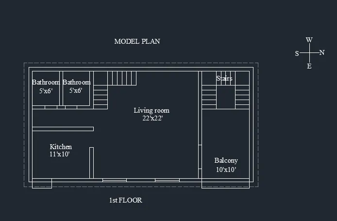
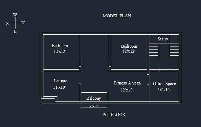
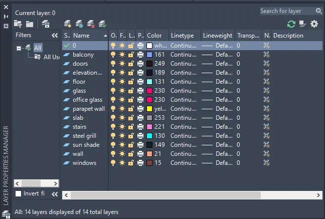
- Using Layers command - I have created separate layers for varying objects and assigned different colors to each layers for better understanding.
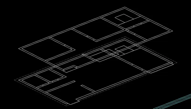
- Using Move command - Place the 2nd floor plan at a vertical distance of 11' above the 1st floor plan.
- I have created the floor slabs and made them into a region.
- Then, Using EXTRUDE command - Extended all floor slabs to a thickness of 8".
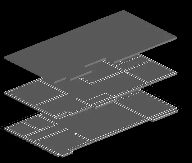
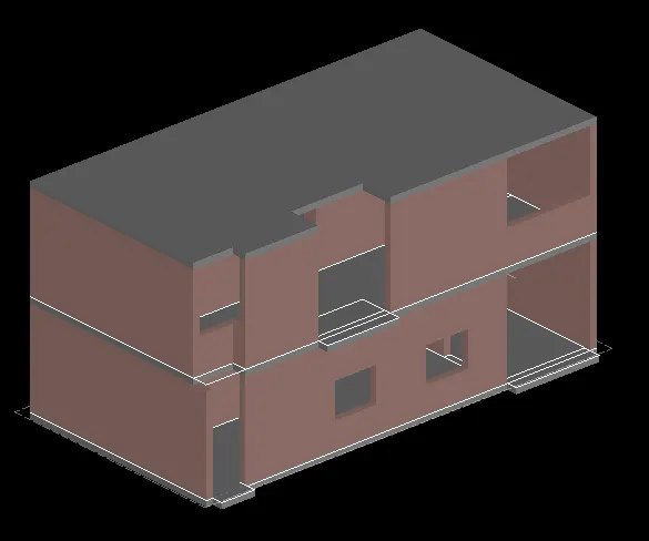
- Using POLYSOLID command - Input Height = 11', Width = 9", I have created the walls for the entire building.
- Also, using SUBTRACT command, I have created the window spacing, door spacing, Space for Glass gazing and spaces for the Balconies in the walls.
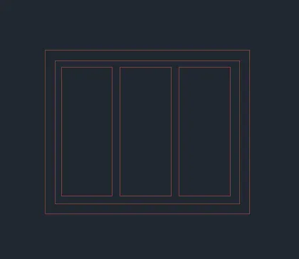
- Using the commands rectangle, polyline - I have created the window structure of 5'x4'.
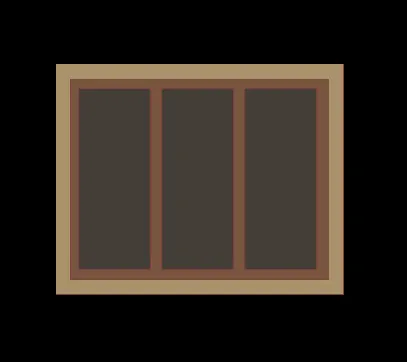
- Then using MATERIAL PROPERTIES, I have assigned TEAK AND PINE wood and SOLID glass material here.
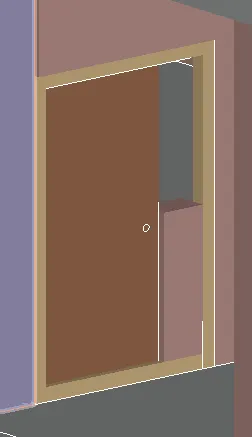
- Similarly, I have created the MAIN DOOR frame and assigned materials using MATERIAL PROPERTIES.
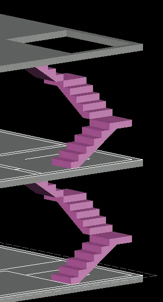
- Using the commands 3P, EXTRUDE - I have created the stairs with riser 8" and Tread 1'.

- After creating the stairs, I have placed it in the building.
- Using the commands Line, 3P - I have created a glass frame first.
- Converted the frame to a region using REGION command.
- Then i have created Individual blocks separately and Made each blocks into a region.
- Now, EXTRUDE the whole frame and blocks to a thickness of 2".
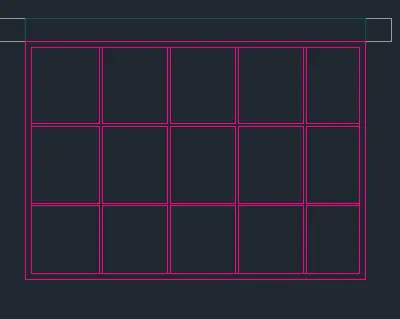
- Now using SUBTRACT command, subtract all the blocks from the frame to create an empty space and get the actual frame like shown below.
- Now, using Rectancle command create rectangles of the size of empty blocks and convert them into regions.
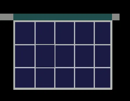
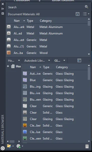
- Now, using MATERIAL PROPERTIES, I have assigned ALUMINIUM METAL to the frame and BLUE GLAZING GLASS to rectangle blocks.
- This is the MATERIAL PROPERTIES window, where I have used different materials throughout the diagram.
- 2nd Floor BALCONY DOOR.
- Using the commands 3P, REGION, EXTRUDE, SUBTRACT - I have created the Glazing Glass door structure for the 2nd floor balcony.
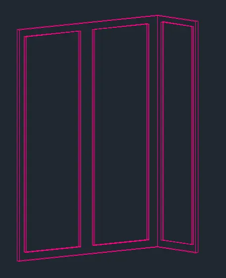
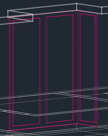
- Then, using move command, I have placed the Glass door structure in the building.
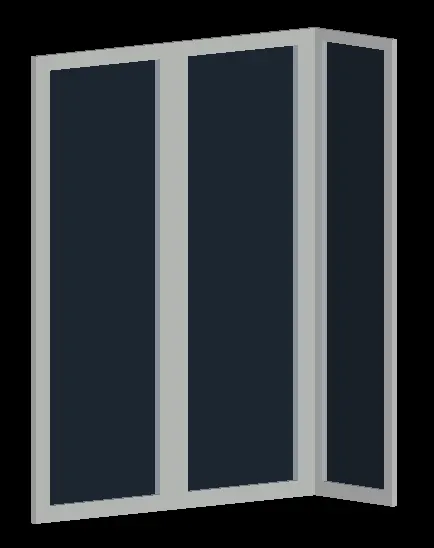
- Using MATERIAL PROPERTIES, I have assigned ALUMINIUM METAL to the frame and BLUE GLAZING GLASS to the rectangle blocks.
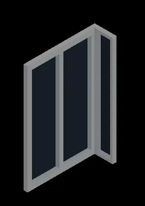
- Similarly, Using the commands 3P, REGION, EXTRUDE, SUBTRACT - I have created the Glazing Glass window structure for the 2nd floor Lounge area.
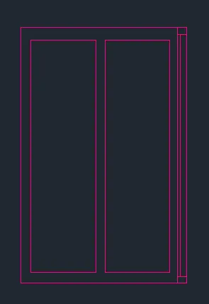
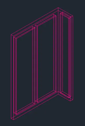
- Again, Using MATERIAL PROPERTIES, I have assigned ALUMINIUM METAL to the frame and BLUE GLAZING GLASS to the rectangle blocks.
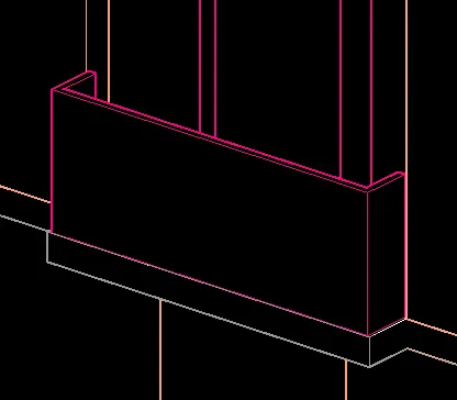
- Using the commands 3P, REGION, EXTRUDE - I have created the 2nd Floor Balcony HAND RAIL of height 4' with 2" thickness.
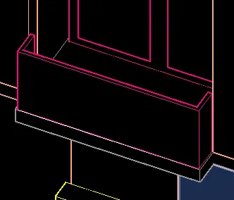
- Another View angle of the balcony hand rail shown below.
- Using MATERIAL PROPERTIES - I have assigned SOLID TRANSLUCENT GLASS to the structure as shown below.
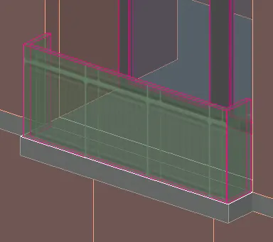
- Different view angles of the balcony are shown below.
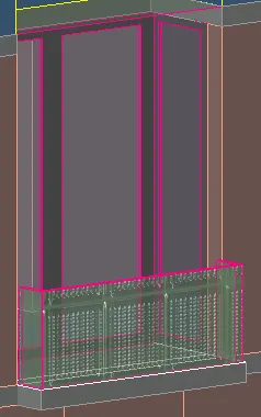
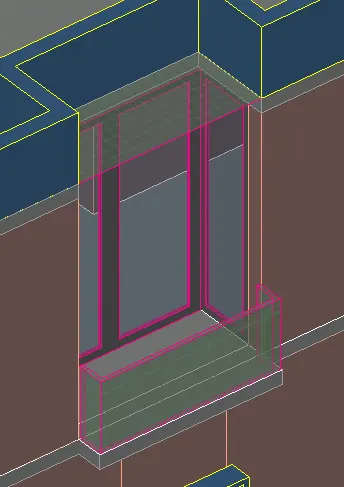
- Similarly, SOLID TRANSLUCENT GLASS material is aslo used at other places as shown below.
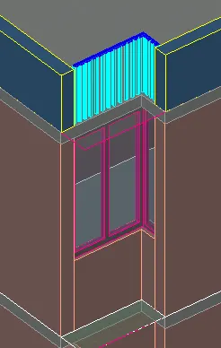
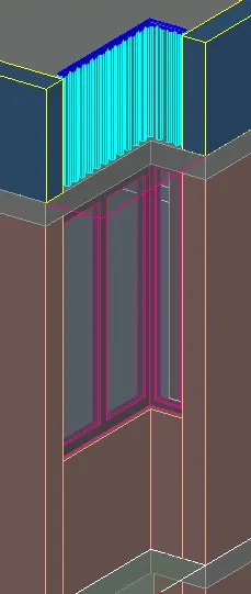
- Using the command POYLSOLID, I have the created the sunshade for the window.
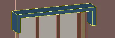
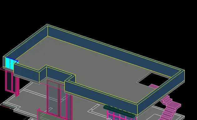
- Again, POLYSOLID command, I have created the Parapet wall as shown below with input height of 4' and width of 9".
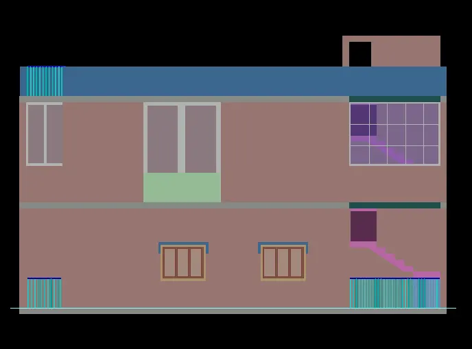
- Front SHADED view of the completed drawing.
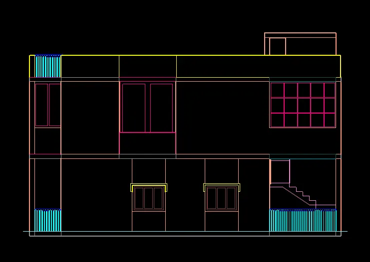
- FRONT Hidden view of the completed drawing.
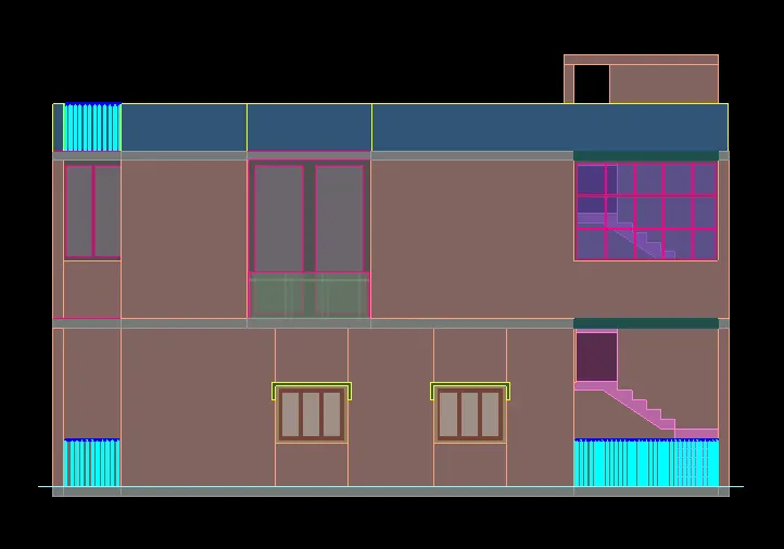
- FLAT WITH EDGES view of the drawing.
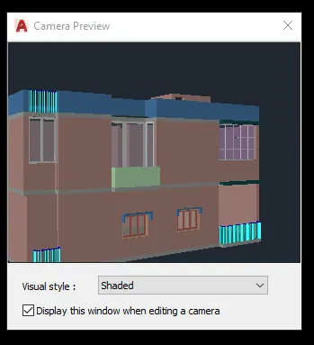
- View of CAM1.
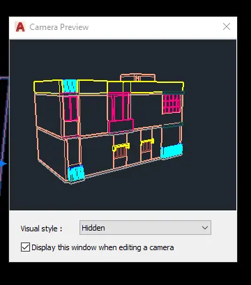
- View of CAM2.
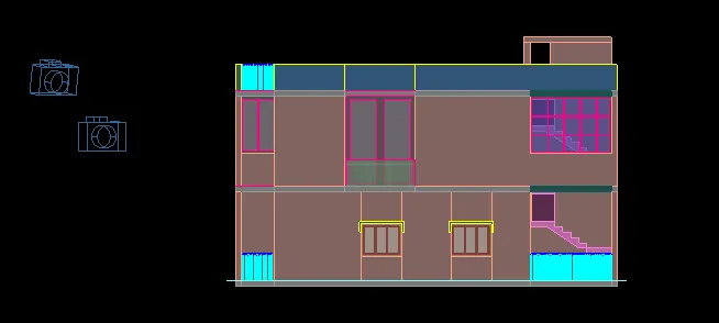
- View with Cameras on.
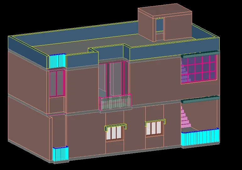
- Isometric 3D view of the Building.
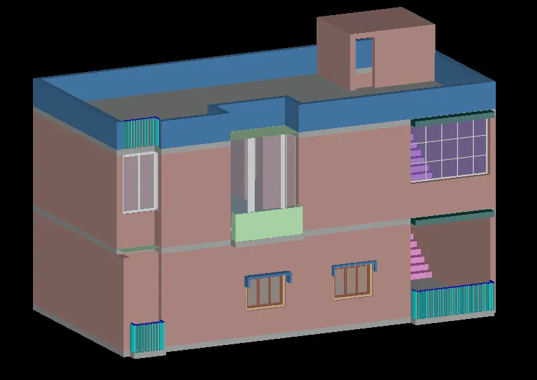
- Isometric Shaded view of the building.
- I have placed distant lights and put them on.
- Using RR command, I have initiated the rendering process.
- Rendered view of the building.
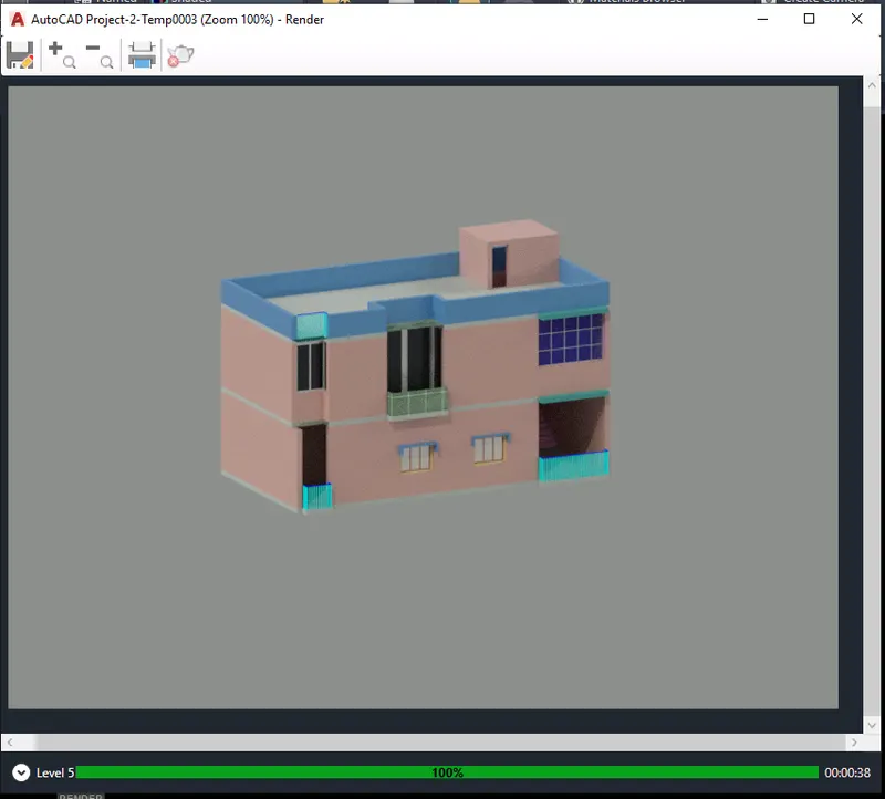
- Here, I have selected the region for rendering.
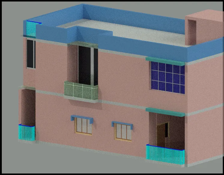
- Here, I have set the Environmental Exposure ON and selected COOL LIGHTS.
- And, Using RR command, I have initiated the rendering process.
- Rendered view of the building with Environmental Exposure on.
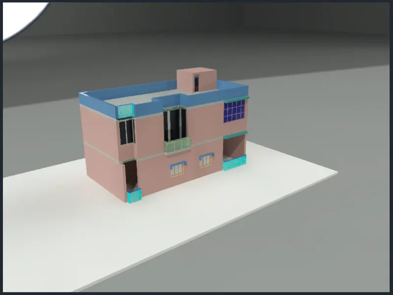
- Different view angle of the rendered image.
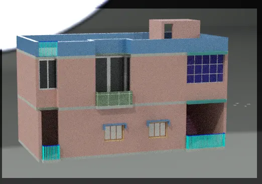
RESULT: