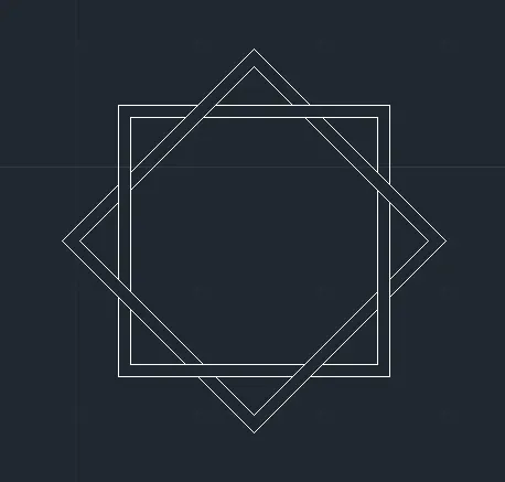
Drafting of various geometries using Chamfer, Fillet tool in AutoCad
1.
AIM:
To draw the diagram 1 using Autodesk AutoCAD software, explain the procedure in detail and show the result.
INTRODUCTION:
AutoCAD is a computer aided design software and drafting software application.
In this project, I have used various commands like units, limits, line, polar tracking, circle, erase to obtain the result.
PROCEDURE:
- Open AutoCAD software
- Choose metric and start from scratch
- Set the units to decimal and select ok
- Ensure the dynamic input is off.
- Specify the limits as lower left corner (0,0) and upper right corner (100,100)
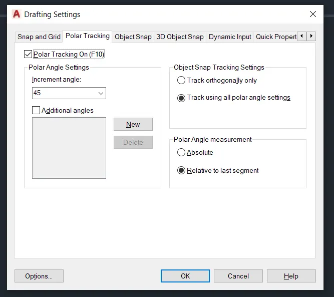
- Go to “polar tracking<set increment angle as 45'<ok"
- Choose line command
- Start the line
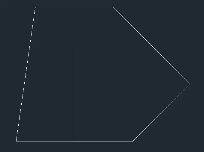
- Specify the next point at a distance 3 @ 0’ in x direction
- Specify the next point at a distance 2.12 @ 45’ relative to the last segment
- Specify the next point at a distance 2.83 @ 90’ relative to the last segment
- Specify the next point at a distance 2.00 parallel to the first line
- Close the line

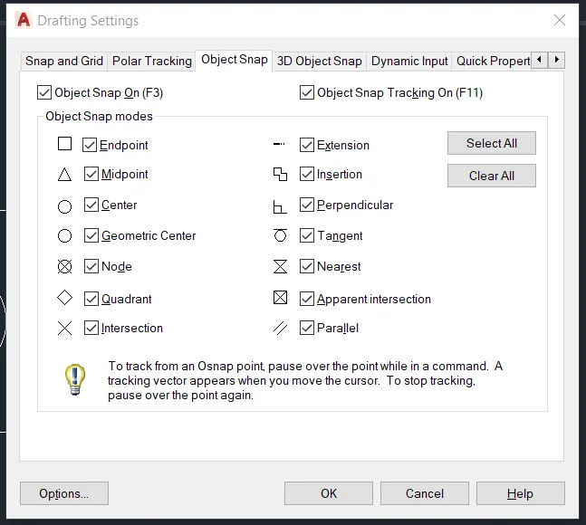
- “Object snap<select all< ok"
- From the midpoint of the first line draw a line of 2.50 perpendicularly inside the object area.
- Take the end of the line as center and draw a circle of diameter 0.80 and erase the line.
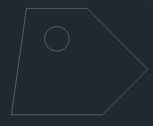
- Again, using the same midpoint of the line draw a line of 1 perpendicularly inside the object area.
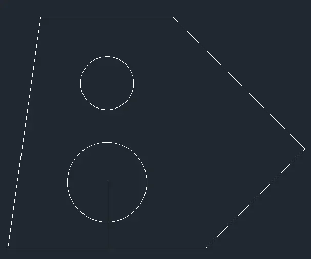
- Take the end of the line as center and draw a circle of diameter 1.20 and erase the line.
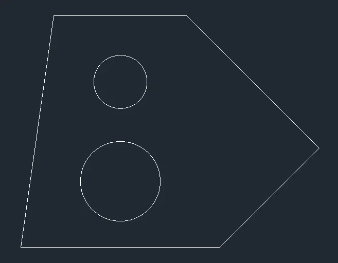
- Therefore, it is the result.
RESULT:
2.
AIM:
To draw the diagram 2 using Autodesk AutoCAD software, explain the procedure in detail and show the result.
INTRODUCTION:
AutoCAD is a computer aided design software and drafting software application.
In this project, I have used various commands like units, limits, line, relative polar coordinates to obtain the result.
PROCEDURE:
- Open AutoCAD software
- Choose decimal and start from scratch
- Set the units to decimal and select ok
- Ensure the dynamic input is off.
- Specify the limits as lower left corner (0,0) and upper right corner (100,100)
- Choose line command
- Start the line
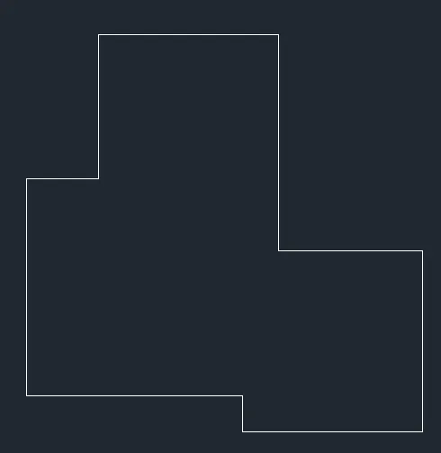
- Specify the 2nd point as (@ 3<0)
- Specify the 3rd point as (@ 0.5<270)
- Specify the 4th point as (@ 2.5<0)
- Specify the 5th point as (@ 2.5<90)
- Specify the 6th point as (@ 2<180)
- Specify the 7th point as (@ 3<90)
- Specify the 8th point as (@ 2.5<180)
- Specify the 9th point as (@ 2<270)
- Specify the 10th point as (@ 1<180)
- And then close the command to complete the drawing.
RESULT:
3.
AIM:
To draw the diagram 3 using Autodesk AutoCAD software, explain the procedure in detail and show the result.
INTRODUCTION:
AutoCAD is a computer aided design software and drafting software application.
In this project, I have used various commands like units, limits, line, relative polar coordinates, offset, circle, erase to obtain the result.
PROCEDURE:
- Open AutoCAD software
- Choose decimal and start from scratch
- Set the units to decimal and select ok
- Ensure the dynamic input is off.
- Specify the limits as lower left corner (0,0) and upper right corner (100,100)
- Choose line command
- Start the line
- Specify the 2nd point as (@ 11.5<0)
- Specify the 3rd point as (@ 6<90)
- Specify the 4th point as (@ 11.50<180)
- Close the line now.

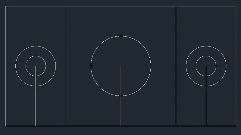
- Using offset command draw lines parallel to the vertical lines at a distance of 3.
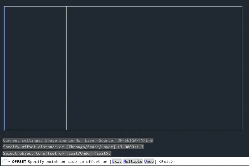
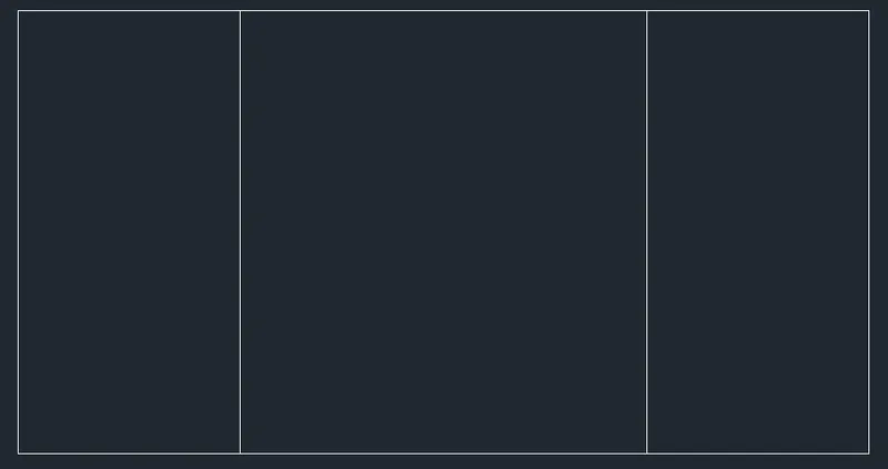
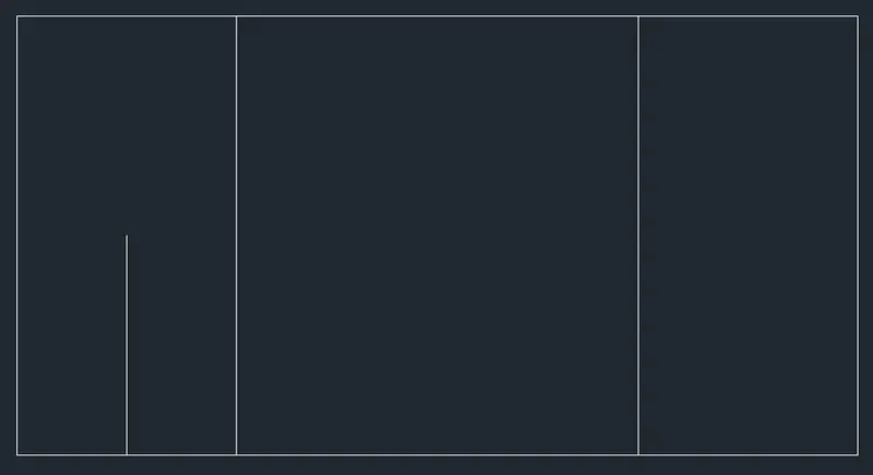
- Draw reference lines of height 3 at a distance of 1.5 from both vertical lines inside the object area.
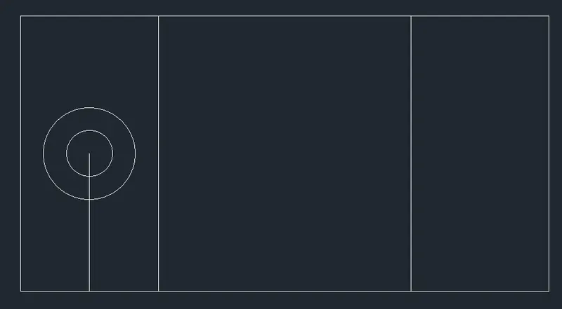
- Using circle with diameter, with the end of line as center draw 2 circles of diameters 1 and 2 on both sides.
- “Object snap< select all< ok"
- Draw a circle of diameter 3 in taking the center of total diagram as center point.
- Then select the reference lines and erase it.
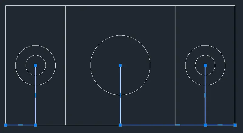
- And then close the command to complete the drawing.
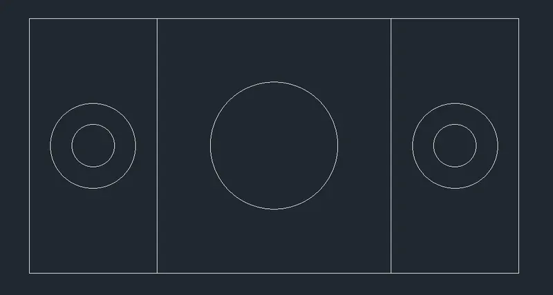
RESULT:
4.
AIM:
To draw the diagram 4 using Autodesk AutoCAD software, explain the procedure in detail and show the result.
INTRODUCTION:
AutoCAD is a computer aided design software and drafting software application.
In this project, I have used various commands like units, limits, line, relative polar coordinates, copy to obtain the result.
PROCEDURE:
- Open AutoCAD software
- Choose decimal and start from scratch
- Set the units to decimal and select ok
- Ensure the dynamic input is off.
- Specify the limits as lower left corner (0,0) and upper right corner (100,100)
- “Object snap < select all< ok"
-
- Choose line command
- Start the line
- Specify the 2nd point as (@ 1.5<0)
- Specify the 3rd point as (@ 0.5<90)
- Specify the 4th point as (@ 1.5<180)
- Close the line now.
- Start the line from top left corner of the object.
- Specify the 2nd point as (@ 1<90)
- Specify the 3rd point as (@ 0.5<0)
- Specify the 4th point as (@ 1<270)
- Close the line now.
- Now using copy command produce two parallel copies of the last object with no gap between them.
-

- Choose line command
- Start the new line
- Specify the 2nd point as (@ 2<0)
- Specify the 3rd point as (@ 1.5<90)
- Specify the 4th point as (@ 0.5<180)
- Specify the 5th point as (@ 1<270)
- Specify the 6th point as (@ 1.5<180)
- Close the line now.
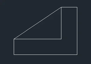
- Using line connect the ends of L shape
- Choose line command
- Start the new line
- Specify the 2nd point as (@ 0.5<0)
- Specify the 3rd point as (@ 1.5<90)
- Specify the 4th point as (@ 0.5<180)
- Close the line now.
- Start the line from bottom left corner of the object.
- Specify the 2nd point as (@ 1.5<180)
- Specify the 3rd point as (@ 0.5<90)
- Specify the 4th point as (@ 1.5<0)
- Close the line now.
- Now using copy command produce two parallel copies of the last object with no gap between them.
-
- And then close the command to complete the drawing.
RESULT:
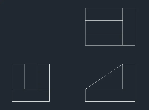
5.
AIM:
To draw the diagram 5 using Autodesk AutoCAD software, explain the procedure in detail and show the result.
INTRODUCTION:
AutoCAD is a computer aided design software and drafting software application.
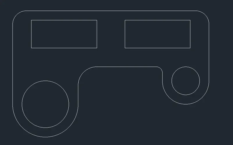
In this project, I have used various commands like units, limits, line, relative polar coordinates, offsets, circle, fillets to obtain the result
PROCEDURE:
- Open AutoCAD software
- Choose decimal and start from scratch
- Set the units to decimal and select ok
- Ensure the dynamic input is off.
- Specify the limits as lower left corner (0,0) and upper right corner (100,100)
- “Object snap < select all<ok"
-
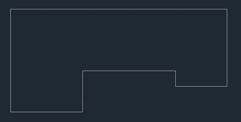
- Choose line command
- Start the line.
- Specify the 2nd point as (@ 100<270)
- Specify the 3rd point as (@ 70<0)
- Specify the 4th point as (@ 40<90)
- Specify the 5th point as (@ 90<0)
- Specify the 6th point as (@ 15<270)
- Specify the 7th point as (@ 50<0)
- Specify the 8th point as (@ 75<90)
- Specify the 9th point as (@ 210<180)
- Close the line.
-
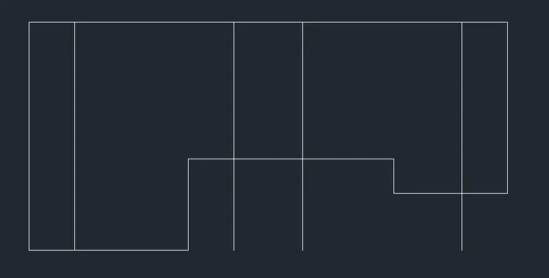
- Using offset command, draw vertical lines at distances of 20, 90, 120, 190 from the right-side line vertical line.
- Using offset command, draw horizontal lines at distances of 10, 40 from the top horizontal line.
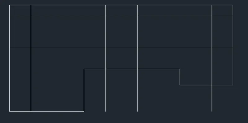
- Using trim command erase the unwanted lines to object the rectangles inside.
-

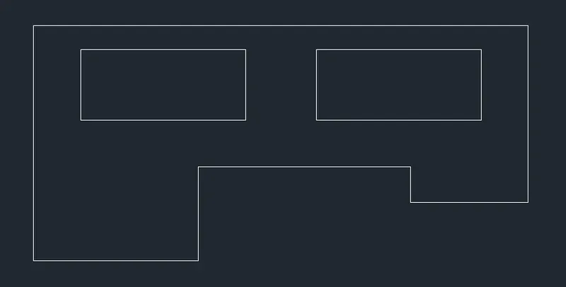
- Provide fillets of,
radius 15 in the top left corner
radius 20 in the 3rd corner anticlockwise to the previous one
radius 15 in the top right corner
radius 16 in the 3rd corner clockwise to the previous one
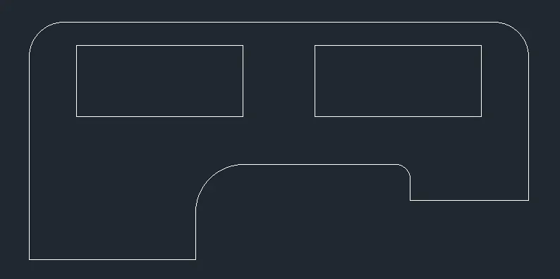
- Provide fillets of radius 35 on left side and radius 25 on right side.

-
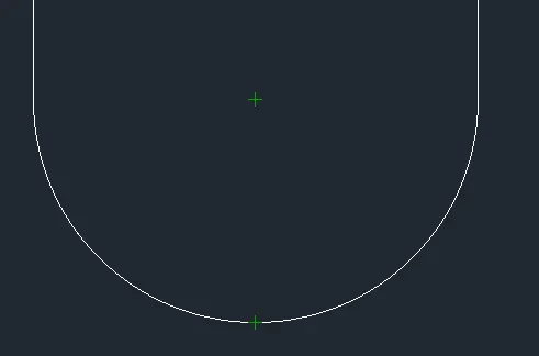
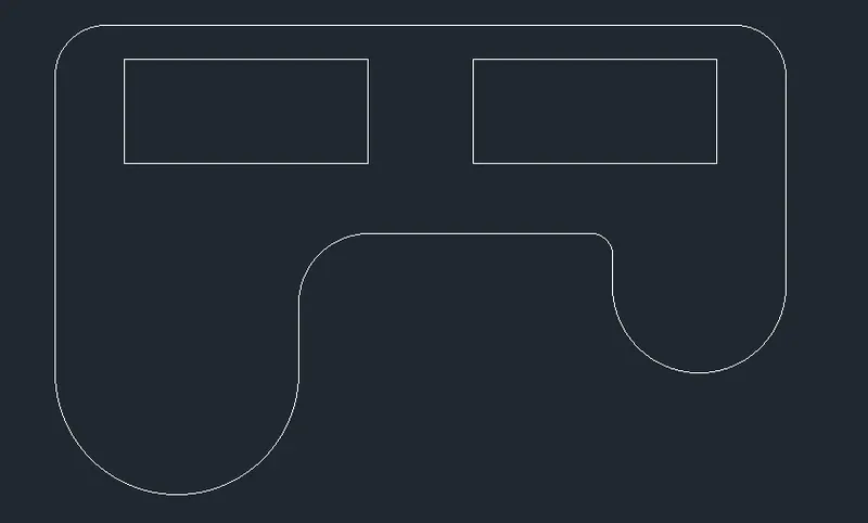
- With Object snap on,
- From the center of the fillets, draw circles of diameter 50 on the left side and diameter 30 on the right side.
- And then close the command to complete the drawing.

RESULT:
6.
AIM:
To draw the diagram 6 using Autodesk AutoCAD software, explain the procedure in detail and show the result.
INTRODUCTION:
AutoCAD is a computer aided design software and drafting software application.
In this project, I have used various commands like units, limits, line, relative polar coordinates, polar tracking, offsets, erase to obtain the result.
PROCEDURE:
- Open AutoCAD software
- Start from scratch
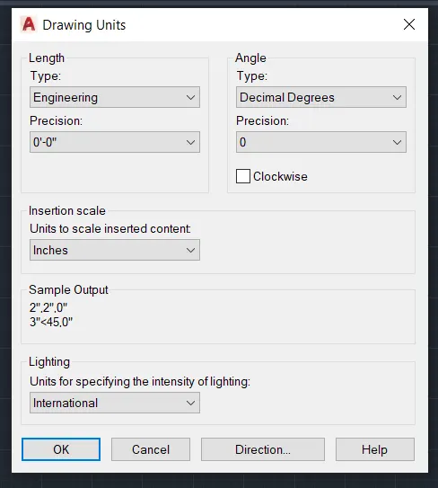
- Set the units to engineering and select ok.
- Ensure the dynamic input is off.
- Specify the limits as lower left corner (0,0) and upper right corner (100,100)
- “Object snap<select all<ok"
-
- Choose line command
- Start the line.
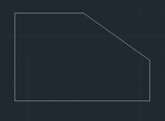
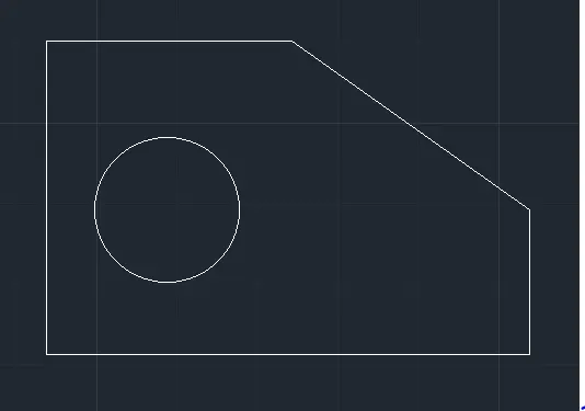
- Specify the 2nd point as (@ 2’6.5” <180)
- Specify the 3rd point as (@ 3’3” <270)
- Specify the 4th point as (@ 5’0.1” <0)
- Specify the 5th point as (@ 1’6” <90)
- Close the line.
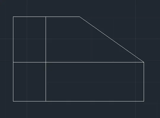
- Using offset command draw vertical line inside at a distance of 1’3” from the left side.
- Using offset command draw horizontal line inside at a distance of 1’6” from the bottom.
- Draw a circle of diameter 1’6” taking the intersection of two lines as center.
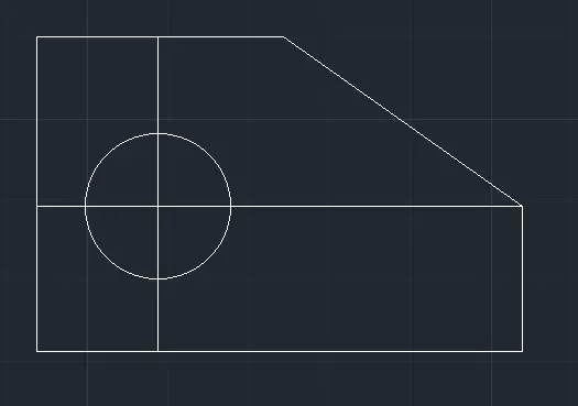
- Now erase the offset lines.
- Thus, the result is obtained.
RESULT:
7.
AIM:
To draw the diagram 7 using Autodesk AutoCAD software, explain the procedure in detail and show the result.
INTRODUCTION:
AutoCAD is a computer aided design software and drafting software application.
In this project, I have used various commands like units, limits, line, relative polar coordinates, polar tracking, offsets, mirror, erase to obtain the result.
PROCEDURE:
- Open AutoCAD software
- Start from scratch
- Set the units to engineering and select ok.
- Ensure the dynamic input is off.
- Specify the limits as lower left corner (0,0) and upper right corner (100,100)
- “Object snap<select all<ok"
-
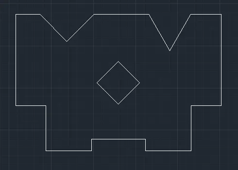
- Choose line command
- Start the line
- Specify the 2nd point as (@ 9’<270)
- Specify the 3rd point as (@ 3’<180)
- Specify the 4th point as (@ 4’6” <270)
- Specify the 5th point as (@ 4’6” <180)
- Specify the 6th point as (@ 1’2” <90)
- Specify the 7th point as (@ 5’4” <180)
- Specify the 8th point as (@ 1’2” <270)
- Specify the 9th point as (@ 4’6” <180)
- Specify the 10th point as (@ 4’6” <90)
- Specify the 11th point as (@ 3’<180)
- Specify the 12th point as (@ 9’<90)
- Specify the 13th point as (@ 10’2” <0)
- Close the line.
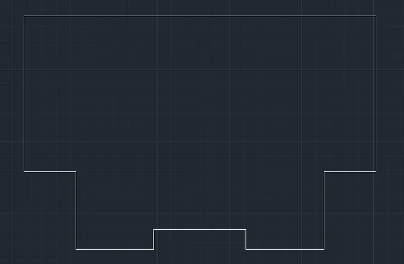
- Split the diagram into two by drawing a center line of length 13’6”
- Take the center of that line as base point and draw a square of sides 3’.
- Now rotate the square, so that two corners of the square touch the line perfectly.
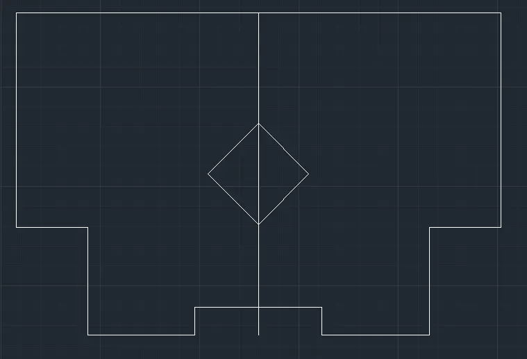
- As the diagram is split in two halves, from the midpoint of the left half from top, draw a line of 2’8” towards down.
- This time from the midpoint of the right half from top, draw a line of 3’7” towards down.
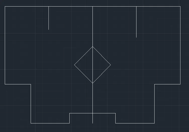
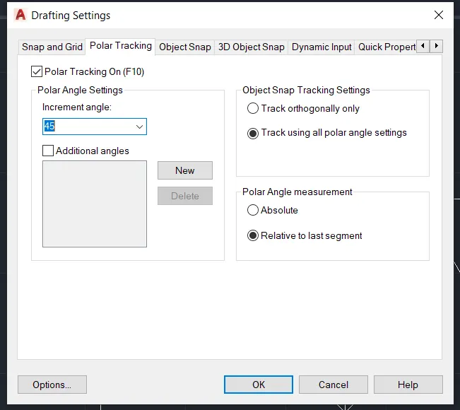
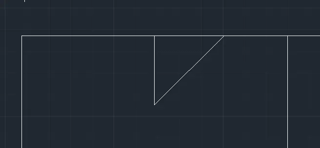
- Now from bottom of left line, draw a line at 45’ angle to meet the top horizontal line and mirror it from the same bottom point as base point to the other side.
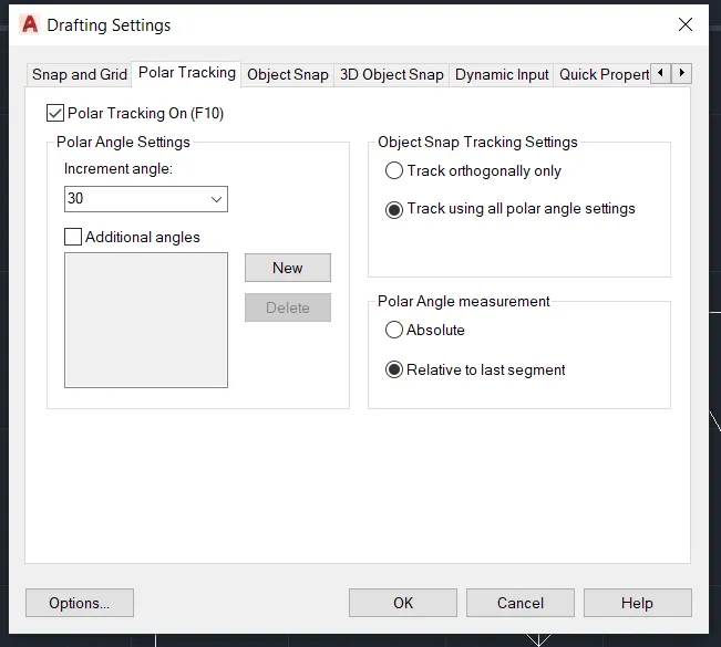
- Again, from bottom of right line, draw a line at 30’ angle to meet the top horizontal line and mirror it from the same bottom point as base point to the other side.

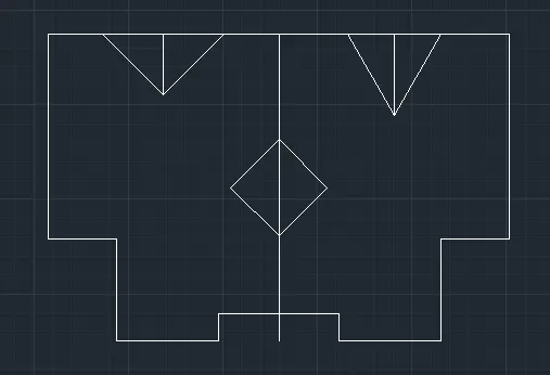
- Now delete all the reference lines finish the diagram.
RESULT:
8.
AIM:
To draw the diagram 8 using Autodesk AutoCAD software, explain the procedure in detail and show the result.
INTRODUCTION:
AutoCAD is a computer aided design software and drafting software application.
In this project, I have used various commands like units, limits, line, relative polar coordinates, polar tracking to obtain the result.
PROCEDURE:
- Open AutoCAD software
- Start from scratch
- Set the units to architectural and select ok.
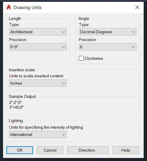
- Ensure the dynamic input is off.
- Specify the limits as lower left corner (0,0) and upper right corner (100,100)
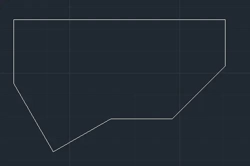
- “Polar tracking< set increment angle as 45’ and add additional angle of 40’ < ok”
-
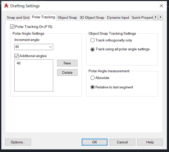
- Choose line command
- Start the line
- Specify the 2nd point via polar tracking at 45’ angle for a distance of 2’10”
- Specify the 3rd point as (@ 1’9” <90)
- Specify the 4th point as (@ 8’<180)
- Specify the 5th point as (@ 2’5” <270)
- Specify the 6th point via polar tracking at 40’ angle for a distance of 3’
- Specify the 7th point at 90’ to the previous line for a distance of 2’6”
- Close the line.
RESULT:
9.
AIM:
To draw the diagram 9 using Autodesk AutoCAD software, explain the procedure in detail and show the result.
INTRODUCTION:
AutoCAD is a computer aided design software and drafting software application.
In this project, I have used various commands like units, limits, line, circle, tangent tangent circle, trim to obtain the result.
PROCEDURE:
- Open AutoCAD software
- Start from scratch
- Set the units to architectural and select ok.
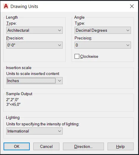
- Ensure the dynamic input is off.
- Specify the limits as lower left corner (0,0) and upper right corner (100,100)
- “Object snap<select all<ok”
-
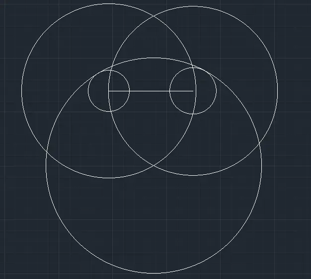
- Draw a line of 32’6” horizontally
- Draw a circle of radius 8’ taking left end of line as center
- Draw a circle of radius 9’ taking right end of line as center
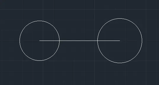
- Again, draw a bigger circle of radius 33’8” taking left end of line as center
- Draw a bigger circle of radius 32’8” taking right end of line as center
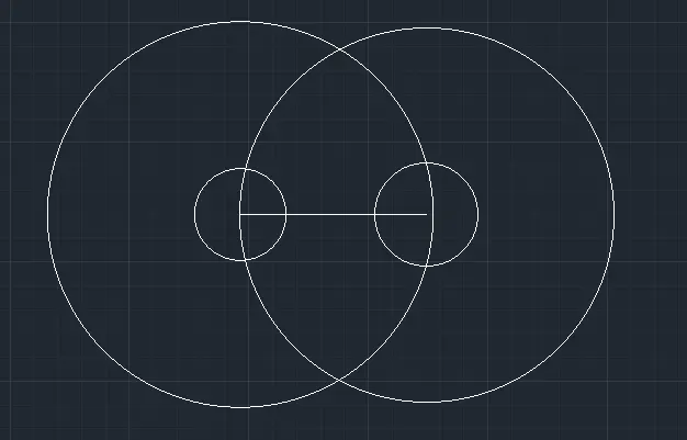
- Now, two bigger circles intersect each other at top and bottom. Take the bottom intersection point as center and draw a circle of radius 41’8”.
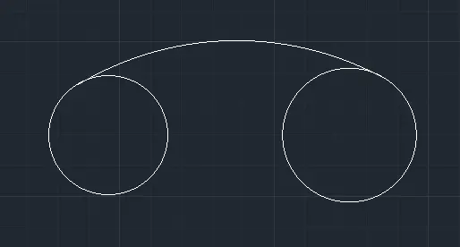
- Now, trim all the outer circle lines, except the two smaller circles and the line that touches it.
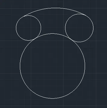
- Now, using “tangent tangent radius” draw a circle of radius 20’10”.
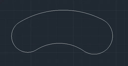
- Using trim command erase all the unwanted lines to obtain the result
RESULT:
10.
AIM:
To draw the diagram 10 using Autodesk AutoCAD software, explain the procedure in detail and show the result.
INTRODUCTION:
AutoCAD is a computer aided design software and drafting software application.
In this project, I have used various commands like units, limits, line, circle, tangent line, erase to obtain the result.
PROCEDURE:
- Open AutoCAD software
- Start from scratch
- Set the units to architectural and select ok.
- Ensure the dynamic input is off.
- Specify the limits as lower left corner (0,0) and upper right corner (100,100)
- “Object snap<select all<ok”
-
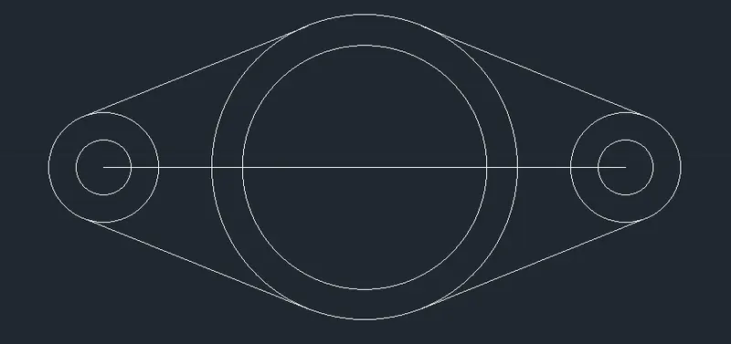
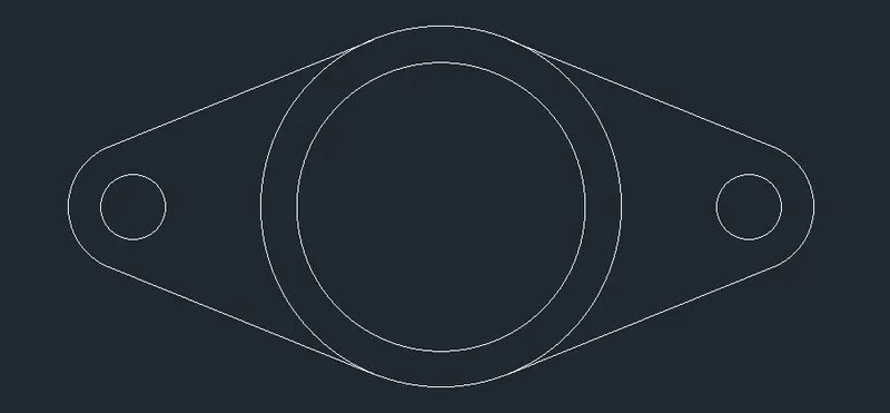
- Draw 2 circles of diameter 4 and 5 with same center point.
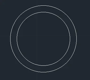
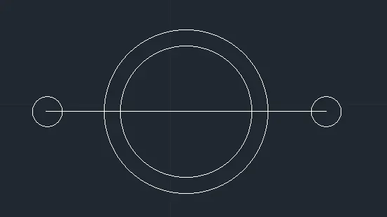
- From that center point draw two lines of length 4.275 horizontally towards left and again towards right.
- Draw two circles one at each end of the line of diameter 0.90
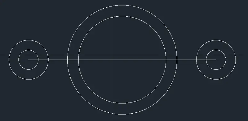
- Again, using same end points as center draw two circles of radius 0.90 at each end.
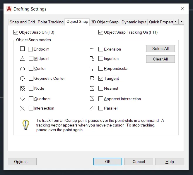
- Ensure “tangent” is checked in “object snap” and connect the outer circles on both sides to the bigger center circle in top and bottom.
- Now, trim the unwanted lines to obtain the result.
RESULT:
11.
AIM:
To draw the diagram 11 using Autodesk AutoCAD software, explain the procedure in detail and show the result.
INTRODUCTION:
AutoCAD is a computer aided design software and drafting software application.
In this project, I have used various commands like units, limits, line, offset, copy, move, trim to obtain the result.
PROCEDURE:
- Open AutoCAD software
- Start from scratch
- Set the units to architectural and select ok.
- Ensure the dynamic input is off.
- Specify the limits as lower left corner (0,0) and upper right corner (100,100)
- “Object snap<select all<ok”
-
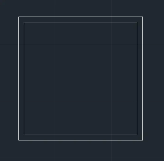
- Draw a square of sides 20’
- Offset the square at a distance of 1’ towards outside in no trim mode
- Now, copy the entire drawing and paste it parallel to it.
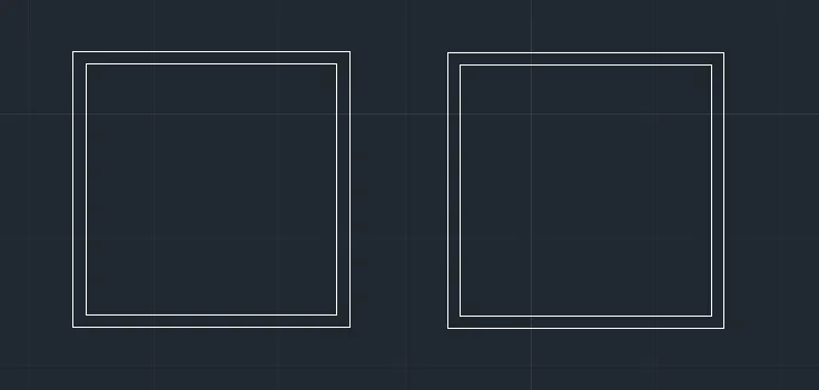
- Connect the center of two squares using a line.
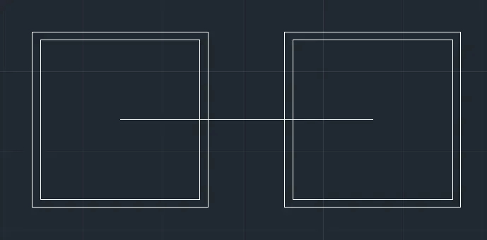
- Now rotate the second square, so that a corner meets the center line.
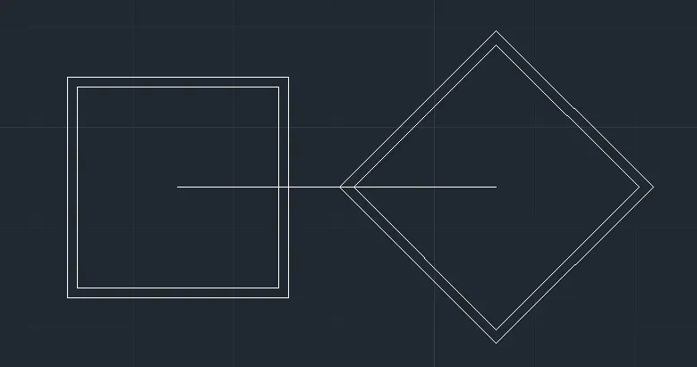
- Now, move the second square and place its center in the center of the first square.
- Erase the center line
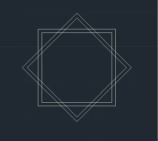
- Using trim command, trim some lines in the overlapping of the squares to obtain the result.
RESULT: