Creating a Floor plan, Footing detail and Isometric view using AutoCad
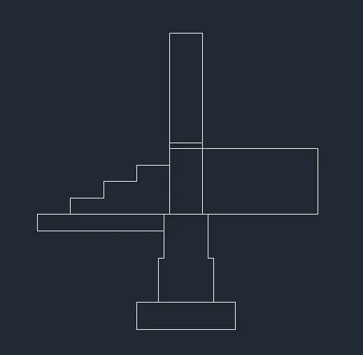
C.S OF LOAD BEARING WALL OVER SPREAD FOOTING
AIM:
To sketch the cross section of load bearing wall over spread footing using Autodesk AutoCAD software.
INTRODUCTION:
Load bearing wall:
A load bearing wall is a wall that supports the weight of a floor or roof above. It bears the load of structural members like slab/roof etc.. and other elements like dead load and live load of the structure is known as load bearing wall.
There are many types of load bearing walls, like
- Precast concrete wall
- Masonry wall
- Retaining wall
- Stone wall
- Metal wall
Spread footing:
Spread footings are commonly used under each column of the buildings or piers in case of bridges. It is economical and cost effective. It suitable for all types of soil if it has an adequate load bearing capacity. It comes under the category of shallow foundation. Spread footing enlarges at the bottom in order to provide individual support to the column/pier.
There are many types, like
- Wall footing
- Isolated footing
- Combined footing
- Strap footing
- Mat/raft foundation etc.
PROCEDURE:
- Set units to decimal
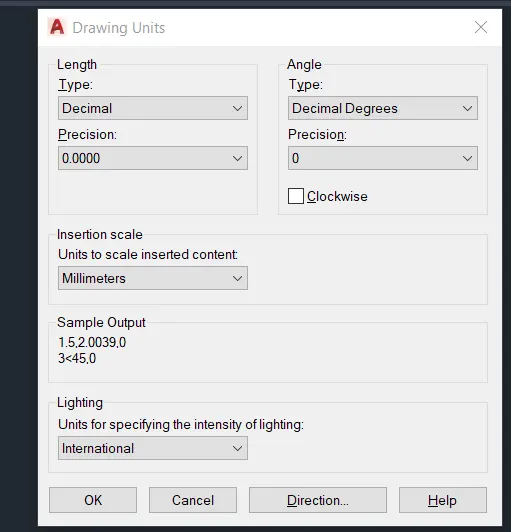
- Limits to lower left as 0,0 and upper right as 420,297 (default)
- Zoom to extents
- Use rectangle command, dimensions 0.90 x 0.25
- Use polyline to draw stem of footing 0.50 x 0.40 and 0.40 x 0.40
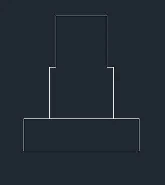
- Use rectangle command, dimensions 1.15 x 0.15 from the top left corner of the stem with rectangle downwards.
- Use polyline, draw 3 steps of 0.30 x 0.15 from the top left end of the rectangle.
- Follow to the right side of the column, then next points @1<0 and @0.60<270 and @1<180.
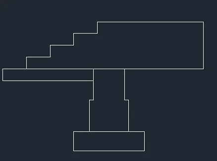
- Draw a column of 0.30 x 1.65
RESULT:
C.S OF ISOLATED FOOTING
AIM:
To sketch the cross section of isolated footing using Autodesk AutoCAD software.
INTRODUCTION:
Isolated footing:
Individual Columns are supported by the isolated footing. Steel reinforcement is provided in both directions in concrete bed for heavily loaded columns. It is the most commonly used footing.
Types of isolated footings,
- Plain/flat
- Stepped
- Sloped
PROCEDURE:
- Set units to decimal
- Limits to lower left as 0,0 and upper right as 420,297 (default)
- Zoom to extents
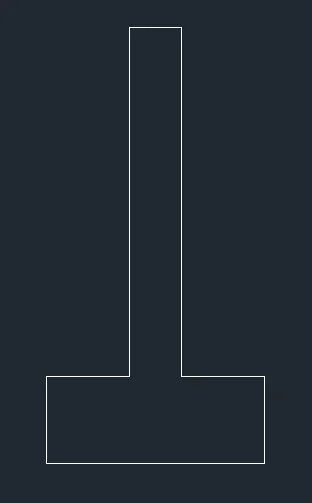
- Polyline command, start the line
- Next points,
@0.40<90
@0.38<0
@1.60<90
@0.24<0
@1.60<270
@0.38<0
@0.40<270
Close the line now.
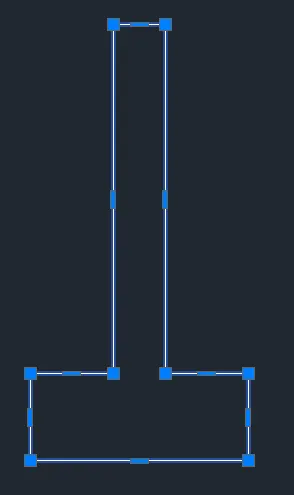
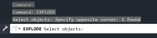
- Command – Explode, to convert to individual members.
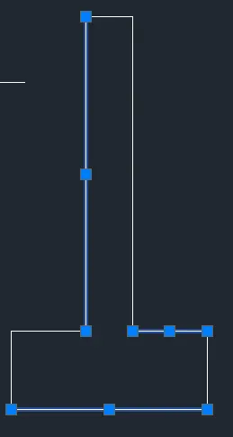
- Command – Chamfer, lines 1.60 & 0.40, Chamfer 1st point as 0.38 and 2nd point as 0.25 and select the lines.

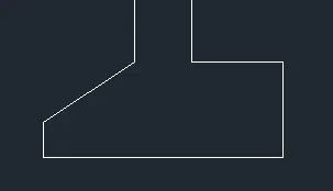
- Repeat the same procedure on the opposite side too.
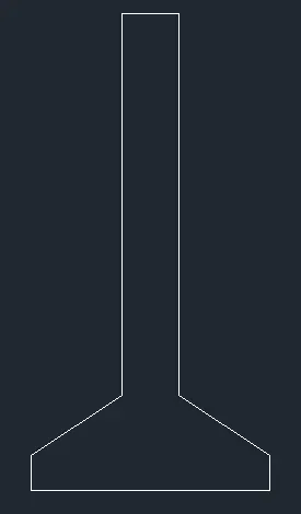
- Command – polyline, from top left corner
@0.04<0
@1.96<270
@0.38<180
@0.05<90
Press – Esc, to end the line.
- Command – polyline, from top right corner
@0.04<180
@1.96<270
@0.38<0
@0.05<90
Press – Esc, to end the line.
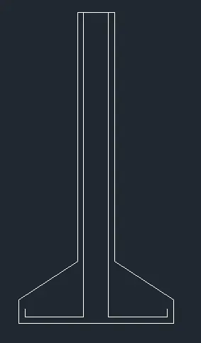
- Command – offset, stirrups @0.20 distance, between the main bars.
RESULT:
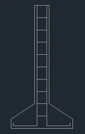
C.S OF LOAD BEARING WALL SHOWING FOUNDATION DETAILS
AIM:
To draw the cross-sectional area of load bearing wall showing foundation details.
INTRODUCTION:
Load bearing wall:
A load bearing wall is a wall that supports the weight of a floor or roof above. It bears the load of structural members like slab/roof etc.. and other elements like dead load and live load of the structure is known as load bearing wall.
There are many types of load bearing walls, like
- Precast concrete wall
- Masonry wall
- Retaining wall
- Stone wall
- Metal wall
Commands used,
Line.
PROCEDURE:
- Set units to decimal
- Limits to lower left as 0,0 and upper right as 420,297 (default)
- Zoom to extents
- Command – line, start the line and next points are,
@0.45<90
@0.15<0
@0.40<90
@0.05<0
@0.30<90
@0.05<0
@0.60<90
@0.05<0
@1<90
@0.30<0
@1<270
@0.05<0
@0.60<270
@0.05<0
@0.30<270
@0.05<0
@0.40<270
@0.15<0
@0.45<270
@0.90<180
Esc to end the line.
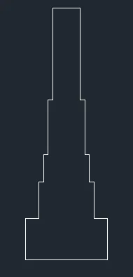
- Using line again, join the gap in the bottom rectangle, to finish the drawing.
RESULT:
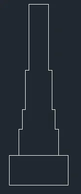
LINE DIAGRAM OF TWO BEDROOM BUILDING
AIM:
To draw the line diagram of two-bedroom building using Autodesk AutoCAD software.
INTRODUCTION:
Commands used:
Rectangle,
Offset,
Lines,
Trim.
PROCEDURE:
- Set units to decimal
- Limits to lower left as 0,0 and upper right as 420,297 (default)
- Zoom to extents
- Command – rectangle, dimensions L – 8.8, W – 3.60.
- Select the rectangle and command explode.
- Command – offset, from left vertical line @3.60 and place inside the rectangle.
- Command – offset, from right vertical line @4.20, place inside the rectangle.
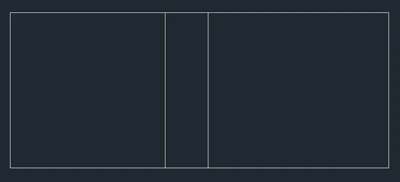
- Command – line, 3 steps, 1 x 0.30.
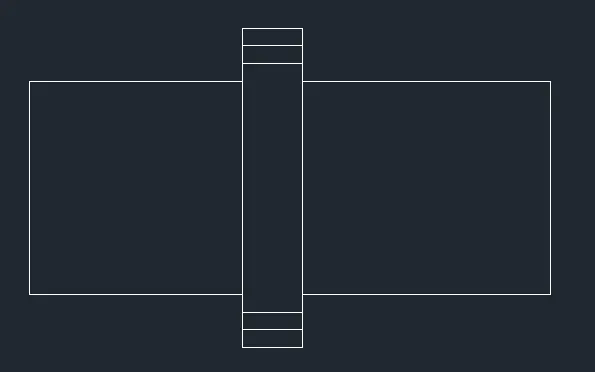
- Command – trim, trim the offset lines.
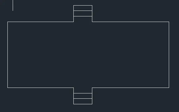
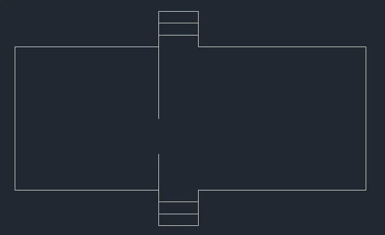
- Command – line, draw 1.80 inside from left side junction of north step and 0.90 from left side junction of south step.
RESULT:
ISOMETRIC VIEW OF STEPS
AIM:
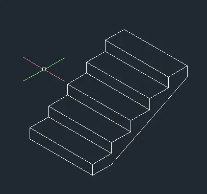
To sketch the isometric view of steps using Autodesk AutoCAD software.
INTRODUCTION:
Commands used:
Line
Ortho on
Iso plane right
Copy
PROCEDURE:
- Set units to decimal
- Limits to lower left as 0,0 and upper right as 420,297 (default)
- Zoom to extents
- Ortho on
- Commands – choose Iso plane right on and use line, create 5 steps of 0.15 rise and 0.30 width.
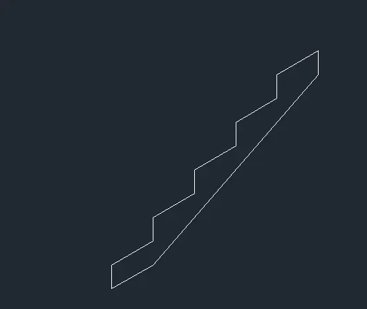
- Command – copy, select all and copy at a distance of 1.
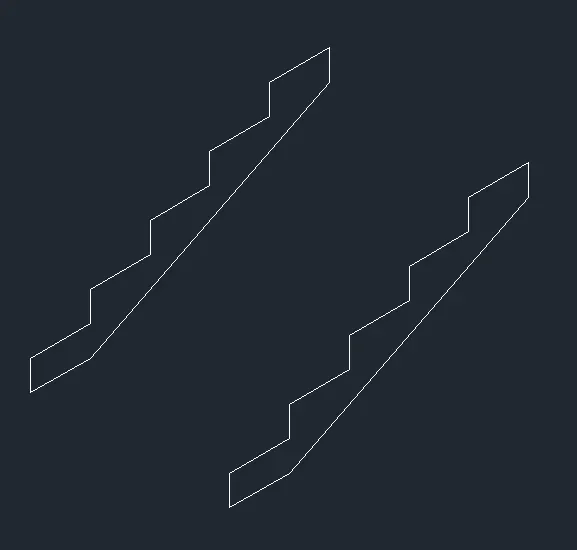
- Command – line, join the edges to form steps
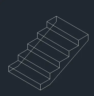
- Command – erase, erase the selected lines.
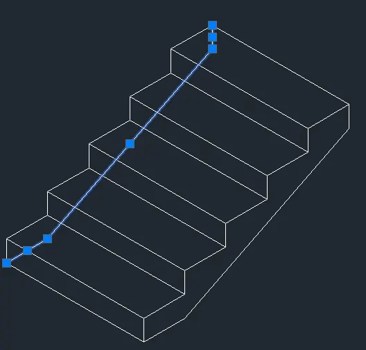
RESULT:
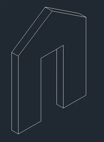
ISOMETRIC VIEW OF GABLE WALL
AIM:
To draw the Isometric view of Gable wall using Autodesk AutoCAD software.
INTRODUCTION:
Commands used:
Iso plane left
Ortho on
Line
Iso plane right
PROCEDURE:
- Set units to decimal
- Limits to lower left as 0,0 and upper right as 420,297 (default)
- Zoom to extents
- Ortho on
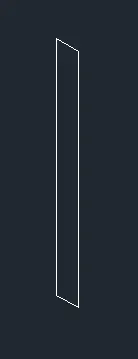
- Commands – Iso plane left and use line, draw a wall of thickness 0.30 and heigh 3.0.
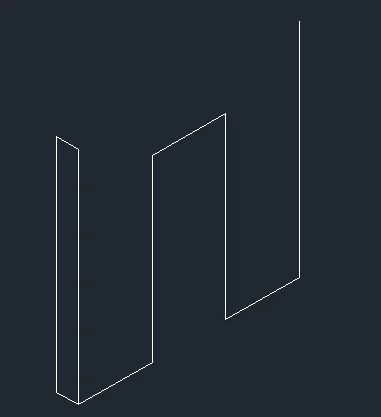
- Commands – Iso plane right and use line to draw the front view, start from front end bottom of finished wall (previous drawing) and next points at,
1.0 right,
2.42 up,
1.0 right,
2.42 down,
1.0 right,
3.0 up
And Esc to end the line.
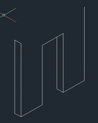
- Command – Iso plane left and line, to draw the thickness of the entrance, start from right side bottom of the entrance, 0.30 left and join perpendicularly to the top.
- Command – line, reference lines to draw the roof,
Join both the walls in the top
Draw a line from bottom center to top of length 4.0.
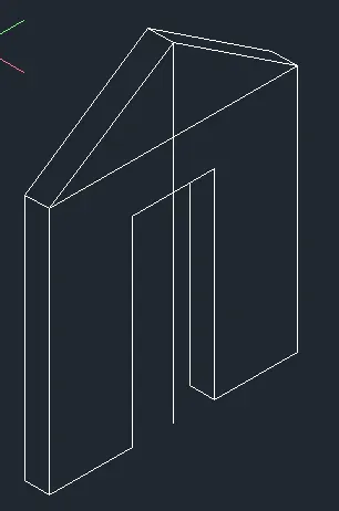
- Command – line, join from both the walls to the center line with the same wall thickness of 0.30 from both ends.
- Command – erase, erase the reference lines to get the result.
RESULT: