Creation of geometries by Coordinate system methods using AutoCad
P1 & P2
AIM:
To draw the diagrams P1 & P2 using all the co-ordinate system methods which are absolute co-ordinates, relative rectangular and relative polar co-ordinates.
INTRODUCTION:
Absolute Co-ordinate system refers to a cartesian system that uses x-axis, y- axis and sometimes a z-axis to establish a point some distance from a common origin. A line can be drawn using absolute coordinates.
Relative co-ordinates are based on last point entered. Use relative coordinates when you know the location of a point in relation to the previous point.
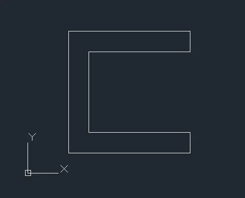
PROCEDURE: (P1 Using absolute co-ordinate)
- Open AutoCAD software
- Choose the imperial template and start from scratch
- Set the units to decimal and select ok
- Ensure the dynamic input is off.
- Specify the limits as lower left corner (0,0) and upper right corner (100,100)
- Choose line command
- Mark the 1st point as (2,1)
- Specify the 2nd point as (8,1)
- Specify the 3rd point as (8,2)
- Specify the 4th point as (3,2)
- Specify the 5th point as (3,6)
- Specify the 6th point as (8,6)
- Specify the 7th point as (8,7)
- Specify the 8th point as (2,7)
- And then close the command to complete the drawing.
RESULT:
PROCEDURE: (P1 Using relative rectangular co-ordinates)
- Open AutoCAD software
- Choose the imperial template and start from scratch
- Set the units to decimal and select ok
- Ensure the dynamic input is off.
- Specify the limits as lower left corner (0,0) and upper right corner (100,100)
- Choose line command
- Mark the 1st point as (2,1)
- Specify the 2nd point as (@ 6,0)
- Specify the 3rd point as (@ 0,1)
- Specify the 4th point as (@ -5,0)
- Specify the 5th point as (@ 0,4)
- Specify the 6th point as (@ 5,0)
- Specify the 7th point as (@ 0,1)
- Specify the 8th point as (@ -6,0)
- And then close the command to complete the drawing.
RESULT:
PROCEDURE: (P1 Using Relative Polar co-ordinates)
- Open AutoCAD software
- Choose the imperial template and start from scratch
- Set the units to decimal and select ok
- Ensure the dynamic input is off.
- Specify the limits as lower left corner (0,0) and upper right corner (100,100)
- Choose line command
- Mark the 1st point as (2,1)
- Specify the 2nd point as (@ 6<0)
- Specify the 3rd point as (@ 1<90)
- Specify the 4th point as (@ 5<180)
- Specify the 5th point as (@ 4<90)
- Specify the 6th point as (@ 5<0)
- Specify the 7th point as (@ 1<90)
- Specify the 8th point as (@ 6<180)
- And then close the command to complete the drawing.
RESULT:
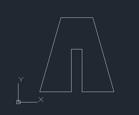
PROCEDURE: (P2 Using absolute co-ordinate)
- Open AutoCAD software
- Choose the imperial template and start from scratch
- Set the units to decimal and select ok
- Ensure the dynamic input is off.
- Specify the limits as lower left corner (0,0) and upper right corner (100,100)
- Choose line command
- Mark the 1st point as (2,1)
- Specify the 2nd point as (5,1)
- Specify the 3rd point as (5,5)
- Specify the 4th point as (6,5)
- Specify the 5th point as (6,1)
- Specify the 6th point as (9,1)
- Specify the 7th point as (7,8)
- Specify the 8th point as (4,8)
- And then close the command to complete the drawing.
RESULT:
PROCEDURE: (P2 Using relative rectangular co-ordinates)
- Open AutoCAD software
- Choose the imperial template and start from scratch
- Set the units to decimal and select ok
- Ensure the dynamic input is off.
- Specify the limits as lower left corner (0,0) and upper right corner (100,100)
- Choose line command
- Mark the 1st point as (2,1)
- Specify the 2nd point as (@ 3,0)
- Specify the 3rd point as (@ 0,4)
- Specify the 4th point as (@ 1,0)
- Specify the 5th point as (@ 0,-4)
- Specify the 6th point as (@ 3,0)
- Specify the 7th point as (@ -2,7)
- Specify the 8th point as (@ -3,0)
- And then close the command to complete the drawing.
RESULT:
PROCEDURE: (P2 Using Relative Polar co-ordinates)
- Open AutoCAD software
- Choose the imperial template and start from scratch
- Set the units to decimal and select ok
- Ensure the dynamic input is off.
- Specify the limits as lower left corner (0,0) and upper right corner (100,100)
- Choose line command
- Mark the 1st point as (2,1)
- Specify the 2nd point as (@ 3<0)
- Specify the 3rd point as (@ 4<90)
- Specify the 4th point as (@ 1<0)
- Specify the 5th point as (@ 4<270)
- Specify the 6th point as (@ 3<0)
- Specify the 7th point as (@ 7.28<106)
- Specify the 8th point as (@ 3<180)
- And then close the command to complete the drawing.
RESULT:
P4
AIM:
To draw the diagram P4 using any co-ordinate system methods.
INTRODUCTION:
Absolute Co-ordinate system refers to a cartesian system that uses x-axis, y- axis and sometimes a z-axis to establish a point some distance from a common origin. A line can be drawn using absolute coordinates.
Relative co-ordinates are based on last point entered. Use relative coordinates when you know the location of a point in relation to the previous point.
PROCEDURE: (P4 Using absolute co-ordinate)
- Open AutoCAD software
- Choose the imperial template and start from scratch
- Set the units to decimal and select ok
- Ensure the dynamic input is off.
- Specify the limits as lower left corner (0,0) and upper right corner (100,100)
- Choose line command
- Mark the 1st point as (2,1)
- Specify the 2nd point as (3,1)
- Specify the 3rd point as (3,5)
- Specify the 4th point as (5,3)
- Specify the 5th point as (7,5)
- Specify the 6th point as (7,1)
- Specify the 7th point as (8,1)
- Specify the 8th point as (8,8)
- Specify the 9th point as (7,8)
- Specify the 10th point as (5,5)
- Specify the 11th point as (3,8)
- Specify the 12th point as (2,8)
- And then close the command to complete the drawing.
RESULT:

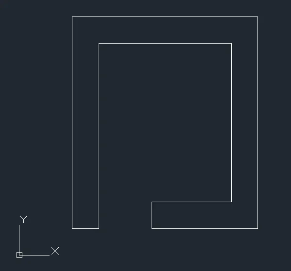
P5
AIM:
To draw the diagram P5 using any co-ordinate system methods.
INTRODUCTION:
Absolute Co-ordinate system refers to a cartesian system that uses x-axis, y- axis and sometimes a z-axis to establish a point some distance from a common origin. A line can be drawn using absolute coordinates.
Relative co-ordinates are based on last point entered. Use relative coordinates when you know the location of a point in relation to the previous point.
PROCEDURE: (P5 Using absolute co-ordinate)
- Open AutoCAD software
- Choose the imperial template and start from scratch
- Set the units to decimal and select ok
- Ensure the dynamic input is off.
- Specify the limits as lower left corner (0,0) and upper right corner (100,100)
- Choose line command
- Mark the 1st point as (2,1)
- Specify the 2nd point as (3,1)
- Specify the 3rd point as (3,8)
- Specify the 4th point as (8,8)
- Specify the 5th point as (8,2)
- Specify the 6th point as (5,2)
- Specify the 7th point as (5,1)
- Specify the 8th point as (9,1)
- Specify the 9th point as (9,9)
- Specify the 10th point as (2,9)
- And then close the command to complete the drawing.
RESULT:
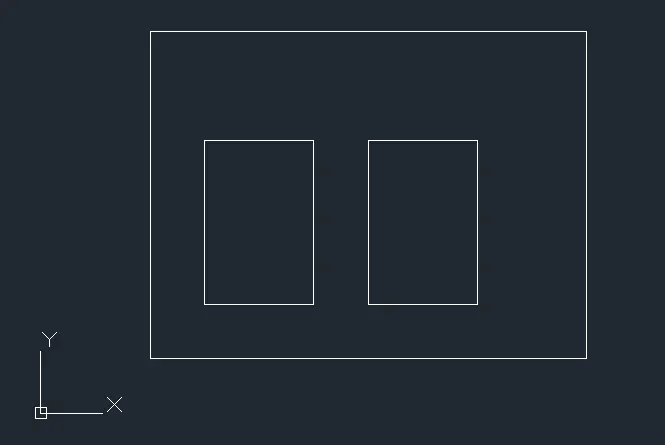
P7
AIM:
To draw the diagram P7 using any co-ordinate system methods.
INTRODUCTION:
Absolute Co-ordinate system refers to a cartesian system that uses x-axis, y- axis and sometimes a z-axis to establish a point some distance from a common origin. A line can be drawn using absolute coordinates.
Relative co-ordinates are based on last point entered. Use relative coordinates when you know the location of a point in relation to the previous point.
PROCEDURE: (P7 Using absolute co-ordinate)
- Open AutoCAD software
- Choose the imperial template and start from scratch
- Set the units to decimal and select ok
- Ensure the dynamic input is off.
- Specify the limits as lower left corner (0,0) and upper right corner (100,100)
- Choose line command
- Mark the 1st point as (2,1)
- Specify the 2nd point as (10,1)
- Specify the 3rd point as (10,7)
- Specify the 4th point as (2,7)
- Close the line now.
- Start from (3,2)
- Specify the next point as (5,2)
- Specify the next point as (5,5)
- Specify the next point as (3,5)
- Close the line now.
- Start from (6,2)
- Specify the next point as (8,2)
- Specify the next point as (8,5)
- Specify the next point as (6,5)
- And then close the command to complete the drawing.
RESULT:
P8
AIM:
To draw the diagram P8 using any co-ordinate system methods.
INTRODUCTION:
Absolute Co-ordinate system refers to a cartesian system that uses x-axis, y- axis and sometimes a z-axis to establish a point some distance from a common origin. A line can be drawn using absolute coordinates.
Relative co-ordinates are based on last point entered. Use relative coordinates when you know the location of a point in relation to the previous point.
PROCEDURE: (P8 Using Relative Polar co-ordinates)
- Open AutoCAD software
- Choose the imperial template and start from scratch
- Set the units to decimal and select ok
- Ensure the dynamic input is off.
- Specify the limits as lower left corner (0,0) and upper right corner (100,100)
- Choose line command
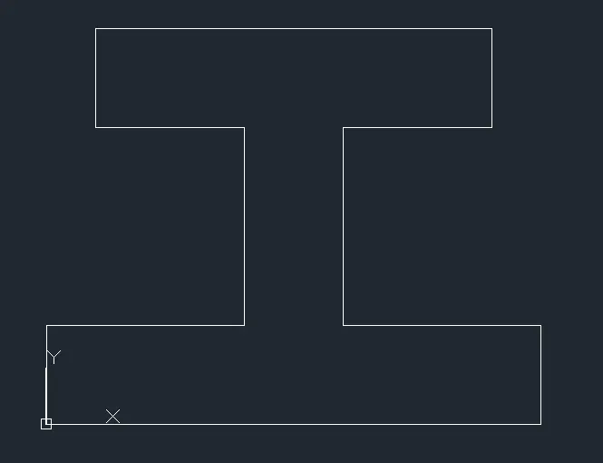
- Mark the 1st point as (0,0)
- Specify the 2nd point as (@ 10<0)
- Specify the 3rd point as (@ 2<90)
- Specify the 4th point as (@ 4<180)
- Specify the 5th point as (@ 4<90)
- Specify the 6th point as (@ 3<0)
- Specify the 7th point as (@ 2<90)
- Specify the 8th point as (@ 8<180)
- Specify the 9th point as (@ 2<270)
- Specify the 10th point as (@ 3<0)
- Specify the 11th point as (@ 4<270)
- Specify the 12th point as (@ 4<180)
- And then close the command to complete the drawing.
RESULT:
P9
AIM:
To draw the diagram P8 using any co-ordinate system methods.
INTRODUCTION:
Absolute Co-ordinate system refers to a cartesian system that uses x-axis, y- axis and sometimes a z-axis to establish a point some distance from a common origin. A line can be drawn using absolute coordinates.
Relative co-ordinates are based on last point entered. Use relative coordinates when you know the location of a point in relation to the previous point.
PROCEDURE: (P9 Using Relative Polar co-ordinates and Absolute Co-ordinates system)
- Open AutoCAD software
- Choose the imperial template and start from scratch
- Set the units to decimal and select ok
- Ensure the dynamic input is off.
- Specify the limits as lower left corner (0,0) and upper right corner (100,100)
- Choose line command
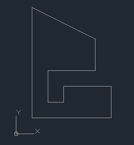
- Mark the 1st point as (1,1)
- Specify the 2nd point as (@ 5<0)
- Specify the 3rd point as (@ 2<90)
- Specify the 4th point as (@ 3<180)
- Specify the 5th point as (@ 1<270)
- Specify the 6th point as (@ 1<180)
- Specify the 7th point as (@ 2<90)
- Specify the 8th point as (@ 3<0)
- Specify the 9th point as (@ 2<90)
- Specify the 10th point as (1,8)
- And then close the command to complete the drawing.
RESULT:
P10
AIM:
To draw the diagram P8 using any co-ordinate system methods.
INTRODUCTION:
Absolute Co-ordinate system refers to a cartesian system that uses x-axis, y- axis and sometimes a z-axis to establish a point some distance from a common origin. A line can be drawn using absolute coordinates.
Relative co-ordinates are based on last point entered. Use relative coordinates when you know the location of a point in relation to the previous point.
PROCEDURE: (P10 Using Relative Polar co-ordinates and Absolute Co-ordinates system)
- Open AutoCAD software
- Choose the imperial template and start from scratch
- Set the units to decimal and select ok
- Ensure the dynamic input is off.
- Specify the limits as lower left corner (0,0) and upper right corner (100,100)
- Choose line command
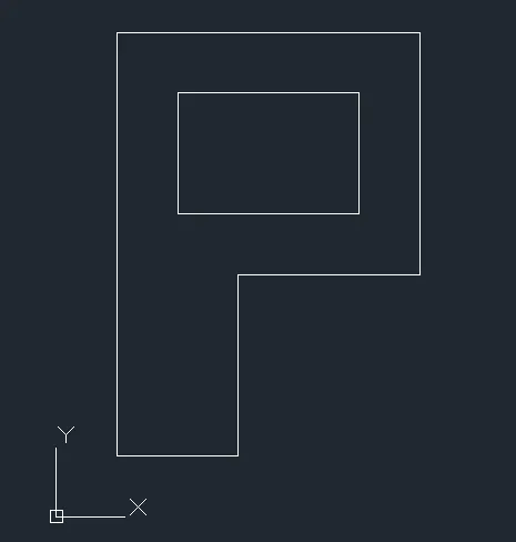
- Mark the 1st point as (1,1)
- Specify the 2nd point as (@ 2<0)
- Specify the 3rd point as (@ 3<90)
- Specify the 4th point as (@ 3<0)
- Specify the 5th point as (@ 4<90)
- Specify the 6th point as (@ 5<180)
- Close the line now.
- Start from (2,5)
- Specify the next point as (@ 3<0)
- Specify the next point as (@ 2<90)
- Specify the next point as (@ 3<180)
- And then close the command to complete the drawing.
RESULT:
PROFILE WOOD:
AIM:
To draw the diagram PROFILE WOOD using any co-ordinate system methods.
INTRODUCTION:
Absolute Co-ordinate system refers to a cartesian system that uses x-axis, y- axis and sometimes a z-axis to establish a point some distance from a common origin. A line can be drawn using absolute coordinates.
Relative co-ordinates are based on last point entered. Use relative coordinates when you know the location of a point in relation to the previous point.
PROCEDURE: (Using Relative Polar co-ordinates)
- Open AutoCAD software
- Choose the imperial template and start from scratch
- Set the units to decimal and select ok
- Ensure the dynamic input is off.
- Specify the limits as lower left corner (0,0) and upper right corner (100,100)
- Choose line command
- Mark the 1st point as (0,0)
- Specify the 2nd point as (@ 10<0)
- Specify the 3rd point as (@ 1<90)
- Specify the 4th point as (@ 2<180)
- Specify the 5th point as (@ 4<90)
- Specify the 6th point as (@ 2<0)
- Specify the 7th point as (@ 1<90)
- Specify the 8th point as (@ 5.831<149.036)
- Specify the 9th point as (@ 5.831<210.964)
- Specify the 10th point as (@ 2<0)
- Specify the 11th point as (@ 5<270)
- Specify the 12th point as (@ 2<180)
- Close the line.
- Draw a circle of radius 2 with center point as (5,4)
RESULT:

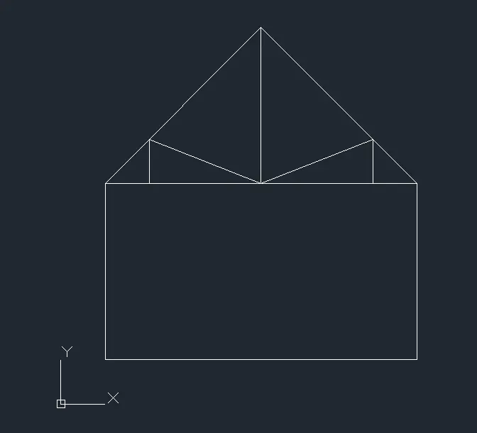
QUEEN POST TRUSS:
AIM:
To draw the diagram QUEEN POST TRUSS using any co-ordinate system methods.
INTRODUCTION:
Absolute Co-ordinate system refers to a cartesian system that uses x-axis, y- axis and sometimes a z-axis to establish a point some distance from a common origin. A line can be drawn using absolute coordinates.
Relative co-ordinates are based on last point entered. Use relative coordinates when you know the location of a point in relation to the previous point.
PROCEDURE: (Using Relative Polar co-ordinates and Absolute Co-ordinates system)
- Open AutoCAD software
- Choose the imperial template and start from scratch
- Set the units to decimal and select ok
- Ensure the dynamic input is off.
- Specify the limits as lower left corner (0,0) and upper right corner (100,100)
- Choose line command
- Mark the 1st point as (1,1)
- Specify the 2nd point as (@ 7.072<0)
- Specify the 3rd point as (@ 4<90)
- Specify the 4th point as (@ 5<135)
- Specify the 5th point as (@ 5<225)
- Close the line.
- Join point 3 & 5 using line.
- Join point 4 to the first intersecting line downwards
- From point 5 (@ 1<0)
- Specify the next point as (@ 1<90)
- Then join to the intersection.
- From point 3 (@ 1<180)
- Then join to the intersection
- Now the diagram is complete.
RESULT:
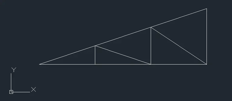
MONOPITCH:
AIM:
To draw the diagram MONOPITCH using any co-ordinate system methods.
INTRODUCTION:
Absolute Co-ordinate system refers to a cartesian system that uses x-axis, y- axis and sometimes a z-axis to establish a point some distance from a common origin. A line can be drawn using absolute coordinates.
Relative co-ordinates are based on last point entered. Use relative coordinates when you know the location of a point in relation to the previous point.
PROCEDURE: (Using Relative Polar co-ordinates and Absolute Co-ordinates system)
- Open AutoCAD software
- Choose the imperial template and start from scratch
- Set the units to decimal and select ok
- Ensure the dynamic input is off.
- Specify the limits as lower left corner (0,0) and upper right corner (100,100)
- Choose line command
- Mark the 1st point as (1,1)
- Specify the 2nd point as (@ 6<0)
- Specify the 3rd point as (@ 2<90)
- Close the line.
- Start from (3,1)
- Join to the slope at 90 degrees angle
- Then specify next point as (5,1)
- Again, join to the slope at 90 degrees angle
- Specify the next point as (7,1)
- Close the line now and the diagram is complete.
RESULT: