Project 2_Creating a 3D rendered model for a Residential Building in AutoCad
Ans Creating a 3D rendered model for a Residential Building in AutoCad
Aim :- Creating a 3D rendered model for a Residential Building in AutoCad.
Introduction :- Creating a 3D rendered model for a Residential Building in AutoCad.
Command used
- Line command
- Dimlinear command
- Text command
- Circle command
- Rectangle
- Trim
- Chamfer
- Offset
- Copy
- Isometric view
- Rectangle
- Trim
- Copy
- Mirror
- Offset
- Polygon
- Point
- Rotate
- Fillet
- Dimlinear command
- Text command
- Extrude
- Sweep
- Union
- Subtract
- Intersect
- Union
- Revolve
- Rotate
- Blocks etc
Procedure :-
Step 1
- Go to Start menu and select new AutoCAD drawing
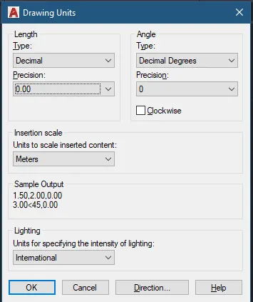
- Select metric, click ok
- Type Units command in command tab and set Unit to Decimal, click ok
- Select 3D modelling
- Set the limits to 900,900
- Visual style is kept as 2D wireframe
Step 2
- Select the top view
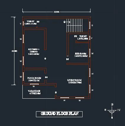
- Draw a floor plan of Ground floor considering Vaastu Aspect
- Draw the ground floor plan by using all commmand needed to draw as command neede to draw the plan
- Provide the dimensions needed
- Add text where and as needed to complete the drawing
Step 3
- Select the top view
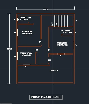
- Draw a floor plan of First floor considering Vaastu Aspect
- Draw the first floor plan by using all commmand needed to draw as command neede to draw the plan
- Provide the dimensions needed
- Add text where and as needed to complete the drawing
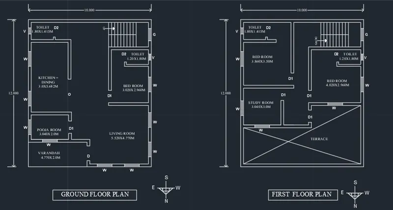
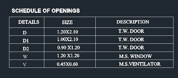
- Create a table containing Schedule of openings
Step 4
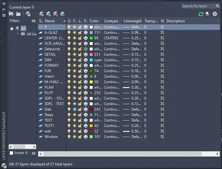
- Click to LAYERS PROPERTIES and layer panel on ribbion
- Click to create new layers to create different layers
- Specify different colours to different layers
Step 5
- Select SW Isometric view
- Set current 3D wall layer
- Change viewstyle to Shaded
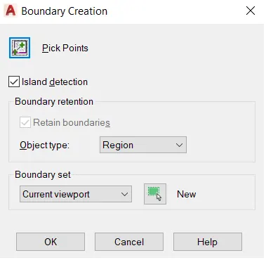
- Enter Boundary command
- Specify object type as Region and click on pick points icon and selcet the boundary
- Click on inside prtion of wall of the floor plans
- Press enter
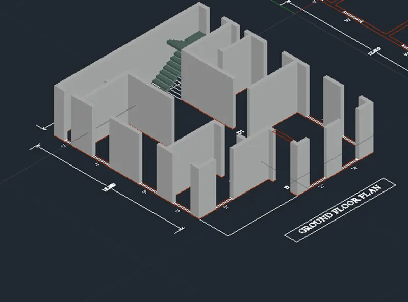
- Enter EXTRUDE or type ext in command box and select the extrude tool
- Selct the boundaries as done in above process
- Press enter
- Five the height as 2.9m
Step 5
- Select rectangle tool or type rec in command tab
- Specify the first corner as any corner point of window, the specify other corner
- Select extrude tool from ribbon
- Extrude to the height of 0.9m i.e. sill level
- Again select rectangle and select the first corner as any corner point of window, the specify other corner
- Select extrude tool from ribbon
- Extrude the rectngle to the height of 870 downwards
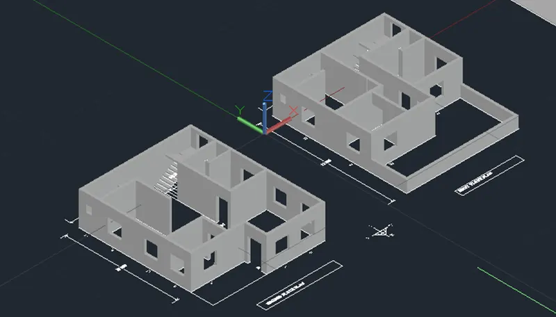
- Similary, create all the doors and window opening to the Ground floor and first floor
- Use the union tool to solid to create, as attach in the pic below
Step 6
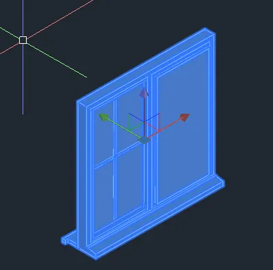
- To create window
- Select rectangle tool or type rec in command tab
- Specify the dimension of windows
- Create a window using all necessary command used for making a window
- Set current 3D window frame layer
- Enter BOUNDARY command in command tab
- Specify the object type as Region and click pick pints icon on boundary creation dialog box
- Click inside the frame of the window
- Press enter
- Selcect subtract tool, and subtract the mullion and glass portion of the window
- Again, Enter BOUNDARY command in command tab and subtract to crrate mullion and glass of window
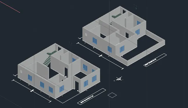
- Copy, paste the window at its position according to the axis
- Rotate it for other direction
- Place the window on the walls
Step 7
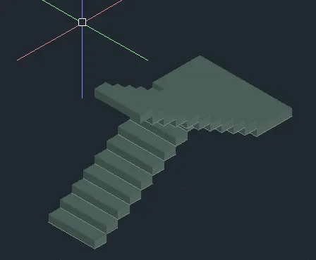
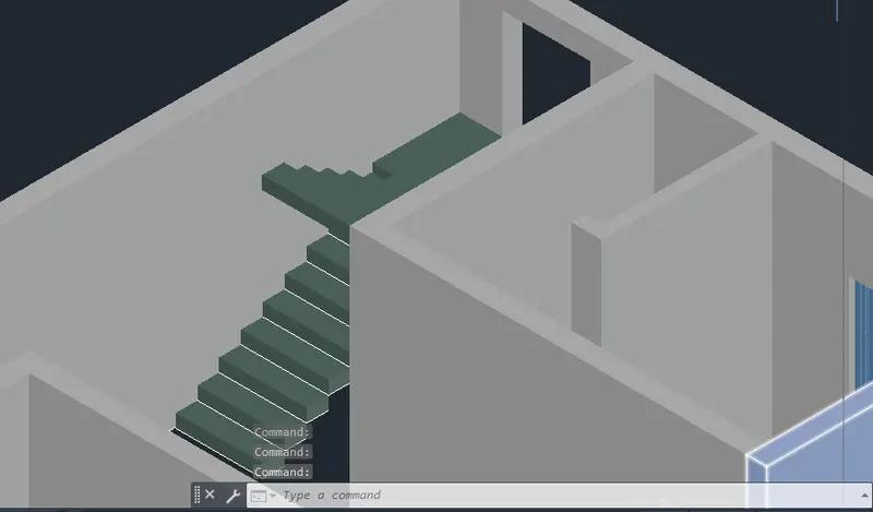
- To create STAircase
- Create the thread (T) and riser (R) as 250mm and 150mm and draw the steps in the top view 2D wireframe
- Landing is 1m and waist slab is of 100mm thickness
- Join all the section of stairs
- Create a region by boundary command
- With 3d orbit place the section in such a way that it is visible
- Extrude 1m towrds the side as 100 is taken as width of stairs
- With 3d rotate select X-axis and give value 90 degrees
- Copy it in all th threds and also in the landing
- For handrails cretae a polyline joining the balustreades by 3D polyline
- Cretae a circle of radius 2" and seep it by selcting the circle and then the polyline
- Thus the steps of staircase is drawn
- Add Staircase part to the planning drawn
Step 8
- To create Slab for the different levels
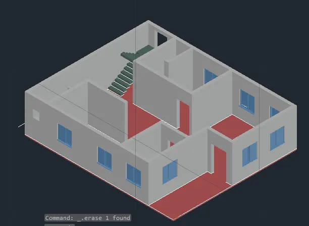
Plinth slab
- Enter ploy in line command and selct POLYLINe tool
- Create outerline of Plinth slab
- Press enter
- Move the floor outline to differnt location
- Create BOUNDARY of outline
- Extrude the height of 100mm thickness
- Copy it to the base of ground floor wall
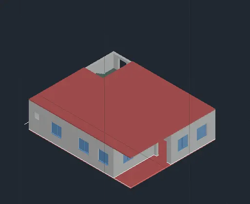
First floor slab
- Enter ploy in line command and selct POLYLINe tool
- Create outerline of Plinth slab
- Press enter
- Move the floor outline to differnt location
- Create BOUNDARY of outline
- Extrude the height of 100mm thickness
- Copy it to the base of ground floor wall
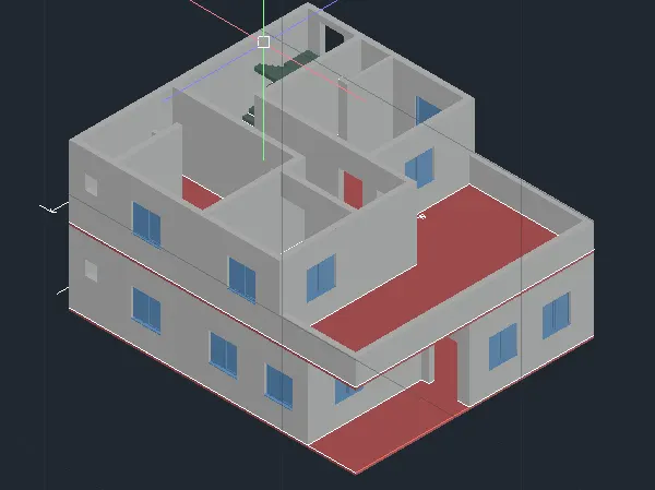
Second floor
- Copy the section drawn of first floor and place it over the First floor slab
- Press enter
- Move the floor outline to differnt location
- Create BOUNDARY of outline
- Extrude the height of 100mm thickness
- Copy it to the base of ground floor wall
Second floor slab
- Enter ploy in line command and selct POLYLINe tool
- Create outerline of Plinth slab
- Press enter
- Move the floor outline to differnt location
- Create BOUNDARY of outline
- Extrude the height of 100mm thickness
- Copy it to the base of ground floor wall
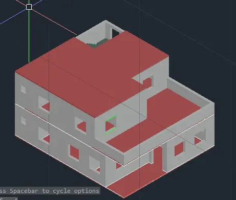
Head Room
- Copy the section drawn of first floor and place it over the Second floor slab
- Press enter
- Move the floor outline to differnt location
- Create BOUNDARY of outline
- Extrude the height of 100mm thickness
- Copy it to the base of ground floor wall
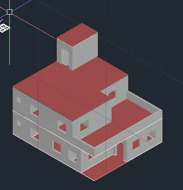
Step 9
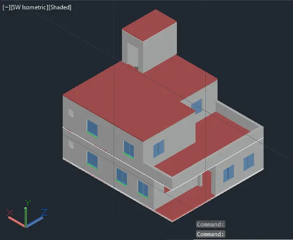
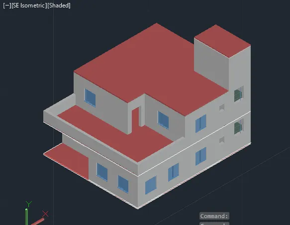
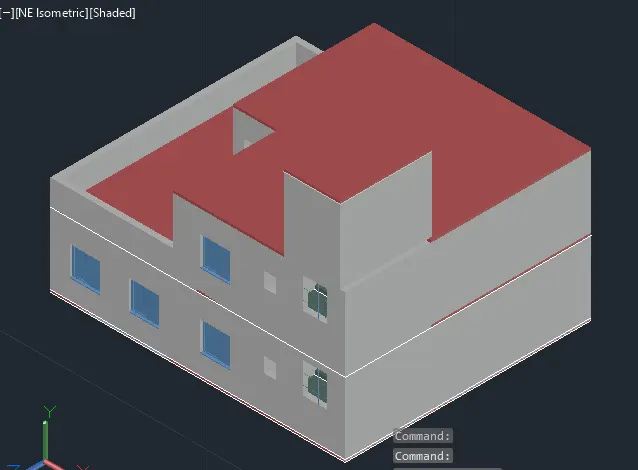
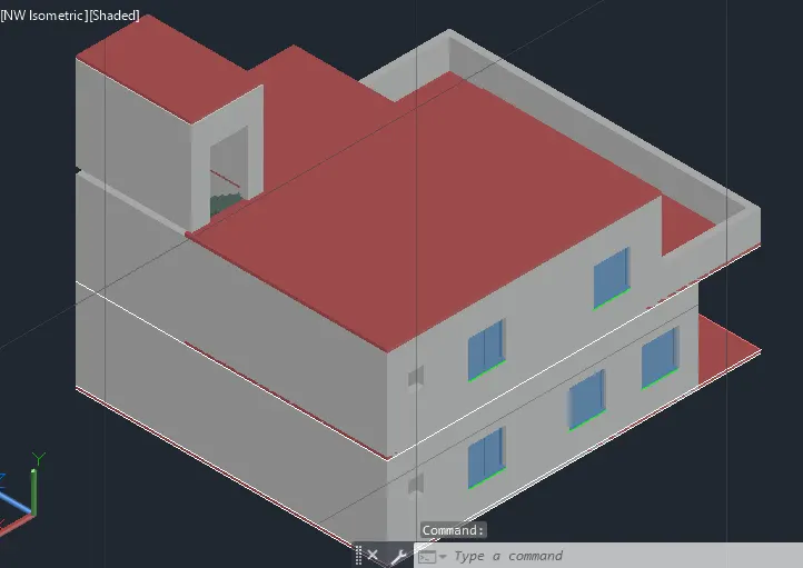
FINAL VIEW OF THE RESIDENTIAL BUILDING
SW ISOMETRIC VIEW
SE ISOMETRIC VIEW
NE ISOMETRIC VIEW
NW ISOMETRIC VIEW
Result :-