Project 2_Creating a 3D rendered model for a Residential Building in AutoCad
A 3D RENDERED MODEL OF A RESIDENTIAL BUILDING IN AUTOCAD :
A ) AIM & INTRODUCTION:
AIM:
- To create a "3D Rendered model of a residential building" in autocad with materials as of our choice in the 3D modeling/basics workspace.
INTRODUCTION:
- A "3D Rendered model of a residential building" is a drawing which was created and rendered in the "3D modeling /basics workspace".
- Here in the 3D modeling space, all drawings can be created in all the 3 axiz such as x,y and z.
- The 3D solid model creating tool from the "tool palette" is used to create this 3D model of a residential building.
- The plan will be created in the 2D workspace and then extruded into the 3D Rendered model of a residential building
- Also the created 3D model of a residential building can be viewed/seen in the "360 degree" to make sure of the shape structure which was created as a 3D model.
- Some of the view tools in the 3D modeling workspace plays the major role for the 3D isometric models they are such as VISUAL STYLE, VIEW CUBE, UCS/UCS ICON.
- With the "Visual style" the visual styles can be changed by customization as required to view the 3D elements, some of the Visual styles such as "2D "Wireframe", "Shaded", "Conceptual", "Hidden", "Realistic".
- With the "View Cube" the various views of the elements can be viewed such as TOP, BOTTOM, RIGHT, LEFT, FRONT ,BACK and so on.
- And with the "UCS/UCS ICON" the differect faces of the 3D models can be created or edited on the "axis plane" such as XY, YZ, ZX.
- In the visual bar selecting the "Materials browser" option the colors of the the isometric views can be made as per the required material property.
- Also, to render the created isometeric view can be rendered with the render option in the "visual bar" .
B ) PROCEDURE:
- First the 2D plan of a residential building should be created as per the given figure and dimensions.
- The plan of a residential building will be created with the required tools and dimensions such as the "line", "rectangle" and "offset" tool.
-
And the dimension are should be denoted by the DIMLINEAR command.
- Then the workspace should be chaged from the DRAFTING AND ANNOTATION to the 3D MODELING (OR) 3D BASICS.
- Then the view of the model space should be extruded as the isometric view with the "VIEW CUBE" by clicking the home button.
- After getting into the 3D MODELING workspace, the created 2D plan of a residential building walls should be extruded with 3D solid extrude tool as per our desired height. Here, it is 10' height from the floor level.
- But before starting the process of extruding the created 2D draft, it should be converted into the region (or) boundary with REGION/BOUNDARY command.
- For that the UCS ICON must be placed at the suitable face with the UCS command such as UCS<FACE<and selecting the face of the 3D element to make the element in the required axis plane.
- To check the 360 degree view of the 3D element, the 3DORBIT command should be used using the command, with this 3D ORBIT tool we can access the 360 view of the element by rotating the mouse pointer.
- To view the 2D wireframed structure as a 3D visual structure, the BOUNDARY or REGION command should be used to make the every face of the element as a single individual face of the object.
- After making a region of a 2D plan, the whole Section of a wall footing should be converted as a union with UNION COMMAND, it will make the individually created sections into the single structure.
- So, it is easy to extrude all walls as region into a single 3D model walls and the distance of the extrution is 13' from the ground level.
- The ROOF SLAB was created as a thickness of 4" by creating a rectangle over the extruded plan and converting that created rectangle into a region, then the region will be allowed to be extruded.
- Over that roof slab a parapet wall was created at the height of 3' from the roof top level as a thickness of 9" with the POLYSOLID TOOL.
- Then the DOOR should be created. Here, the dimesions of the DOOR was @7',4' with the outer frame and the inner frame along with wood design at center by assuming the design and dimensions.
- Then the WINDOWS should be created. Here, the Dimensions of the "FRONT WINDOW" and "HALL WINDOWS" was @4',6' with the WINDOW DOOR PANELS and GLASSES.
- Likewise the Dimensions of the "ROOM WINDOWS" were @3',4' along with the WINDOW DOOR PANELS and GLASSES.
- After the complete creation of the 3D model of a residential building it should be allowed to be look in the suitable color as per the material used in the structure.
- The walls, concrete structures, door, windows and other structures can be colored as per its material properties to look real as it is, and it can be done by using the MATERIAL BROWSER < VISUAL BAR.
- The required "Lighting" can also be attached inside the created 3D model of a residential building with the light settings in the VISUAL BAR.
- Then the Created 3D model of a residential building will be allowed to render by using the render tool in the VISUAL BAR.
- The rendering of 3D model of a residential building will be adjusted in the render option such as RENDER OPTION < QUALITY OF THE RENDERING < RENDER AS REGION < RENDER.
- After the customizing the rendering option, the region where the 3D should be rendered to be selected as window and it will be rendered.
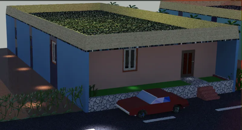
NOTE : A 3D Rendered model of a residential building is shown below for reference.
C ) RESULT:
- It is a 3D Rendered model of a residential building and it was created in the 3D modeling/basics workspace with RENDERING OPTION.
- The shown 3D Rendered model of a residential building is view from the "Home view" of the VIEW CUBE.
- This3D Rendered model of a residential building is created in all the 3 axis such as "x, y and z".
- The walls, roofs, steps, windows and door of the residential building is created as a 2D drawing and extruded as a 3D view.
- The faces of this 3D Rendered model of a residential building are made into single object with the "UNION" tool.
- By placing the UCS icon at the required face of the 3D model, the faces can be edited individually along its axis plane.
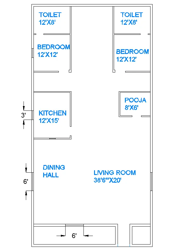
2D PLAN OF A RESIDENTIAL BUILDING
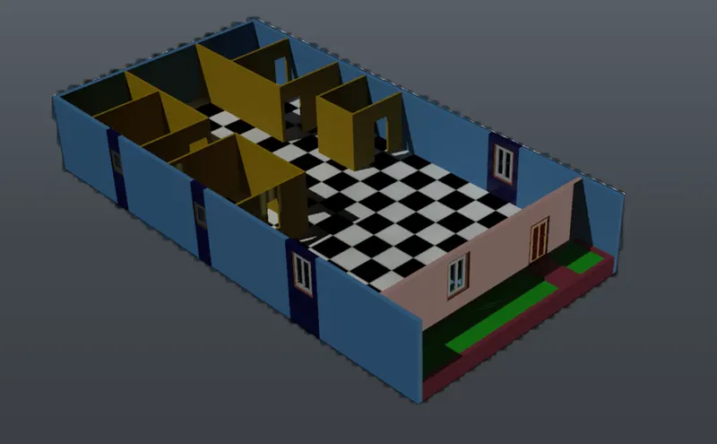
TOP VIEW OF THE RENDERED RESIDENTIAL BUILDING WITHOUT "ROOF SLAB"
VIEW OF THE RENDERED RESIDENTIAL BUILDING
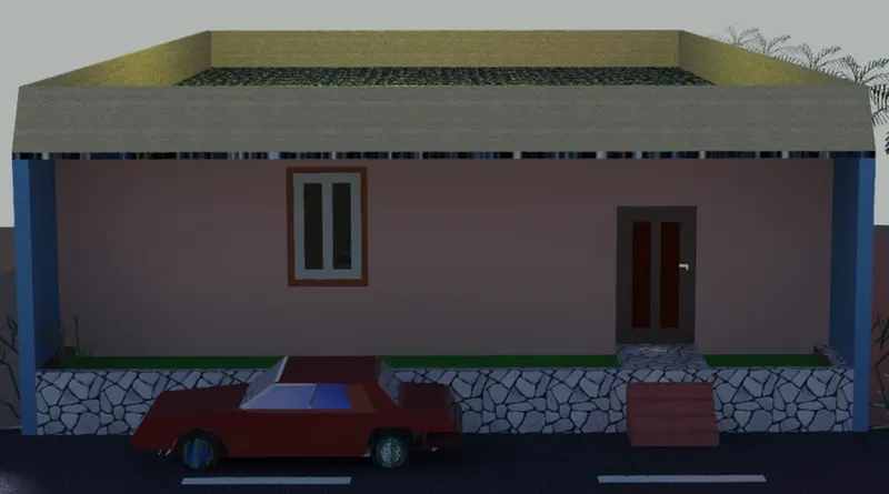
FRONT VIEW OF THE RENDERED RESIDENTIAL BUILDING
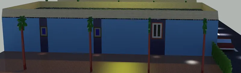
SIDE VIEW OF THE RENDERED RESIDENTIAL BUILDING
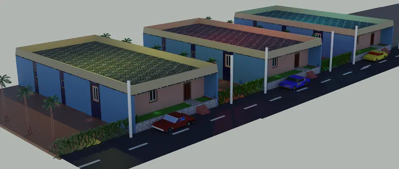
FULL VIEW OF THE RENDERED THREE RESIDENTIAL BUILDINGS