Project 2_Creating a 3D rendered model for a Residential Building in AutoCad
AIM: TO CREATE A FULL-FLEDGED 3D RENDERED MODEL OF A RESIDENTIAL BUILDING USING AUTOCAD.
INTRODUCTION:
AutoCAD is pretty functional when it comes to 2d designing and drafting of various structures including residential apartment buildings. All the tools and commands within the software let you create every little piece of information in the building in different layers that can be edited likewise in the future. The entire building plan, section, and elevation can be drawn efficiently when one knows the relevant commands and how to utilize them according to the need of the drawing.
At the same time, AutoCAD also has a 3d modeling workspace where you can create 3d models of the structures you have planned in the 2d wireframe. Creating the 3d model can be primarily divided into three steps. At first, you create the 2d wireframe of the proposed building. Then, you can transform it into a solid model that can be edited according to the need. And at last, the solid model then can be rendered to create realistic visualized views of the final building. So, the same approach is followed in this project as well. In this project, the complete 3d model of a residential building is created from scratch. Everything starting from the planning phase to rendering the 3d view is covered using the relevant tools and commands.
This project is divided into three phases each phase containing a specific stage in the building process using AutoCAD. All four phases covered in this project are listed below:
- Planning and drafting of the G+4 residential building using 2d drafting and annotations workspace.
- Creating a 3d solid model out of the proposed 2d plan of the building.
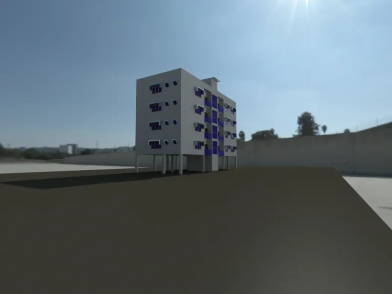
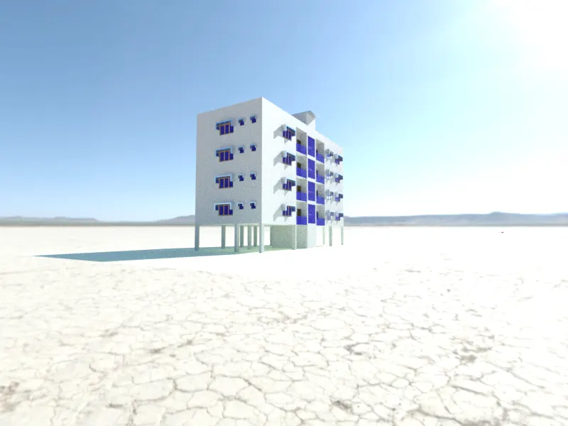
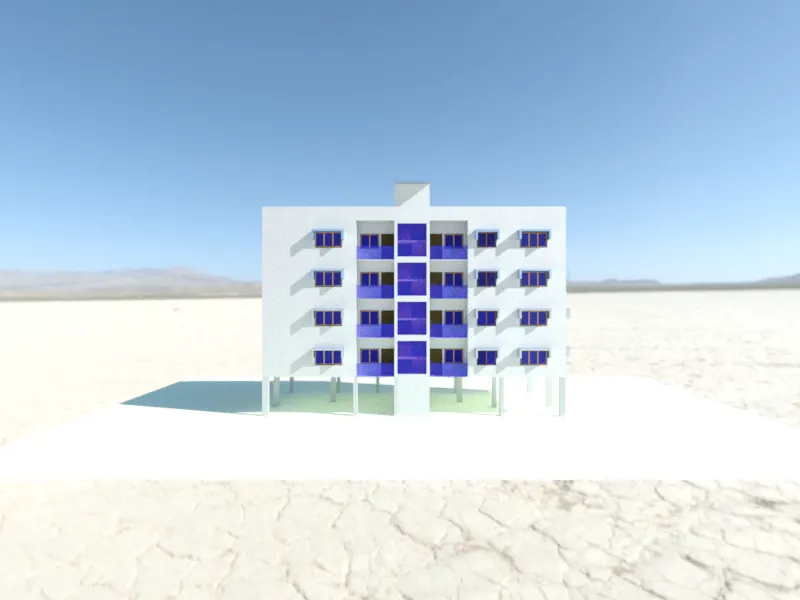
- Rendering the solid model to create the realistic visuals of the building.
PHASE ONE: Planning and drafting the G+4 residential apartment building within a specified built-up area.
STEPWISE PROCEDURE:
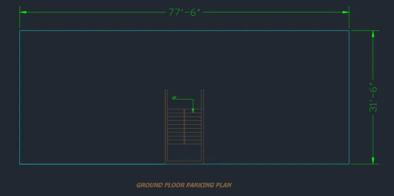
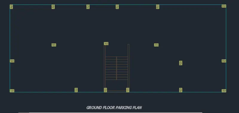
- Create the ground floor parking plan and locate the staircase within the central range of the building.
- Create the pre-specified built-up area of the size 77'-6" x 31'-6" using the rectangle command.
- Create the staircase from the bottom central portion of the parking lot.
- Use line, offset and, extend commands to lay down the tread, landing, and railing plan within the staircase.
- Create the standard landing dimension of 8' x 4' and 11" wide tread for the staircase.
- Also, use a different layer for both components.
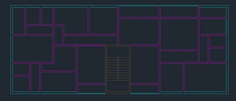
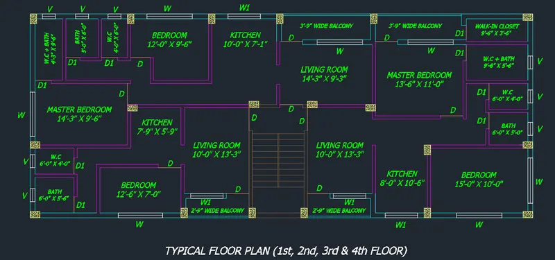
- Design the typical floor plan within the same Built-up range by efficient space management.
- Divide the built-up area into four equal sections to visualize the size we have on our side.
- Start fitting the first flat from the right section see how many rooms can be adjusted.
- Complete the first flat by placing two bedrooms (including one master bedroom), a kitchen, common toilet, and bathroom, and the living room including a balcony.
- Follow the same approach to create another flat with the same number of rooms.
- See how much of space is left and adjust the third flat accordingly.
- Since large room dimensions are put in place including master bedrooms as well as walk-in closets, only three apartments were adjusted within the said built-up space.
- Thus, complete the overall layout of the typical floor plan.
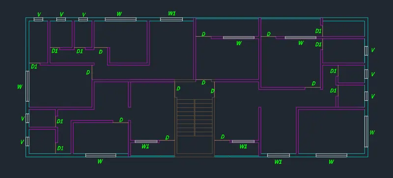
- Adding up the doors and windows in the typical floor plan.
- Create separate layers for doors and windows.
- Use the industry-standard doors and window sizes.
- Adjust the space within the building according to the horizontal as well as vertical movement within the building and place the doors and windows accordingly.
- Make sure to take note of the wind speed, wind direction, sunlight exposure, and all other relevant factors while placing the doors and windows of the apartments.
- Give notations to doors and windows as per their sizes and group them accordingly.
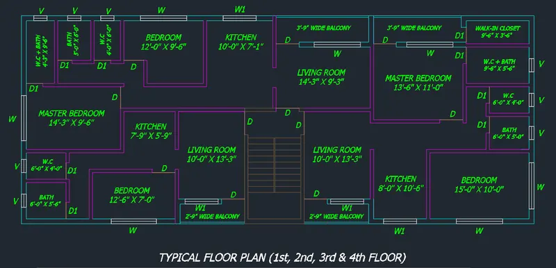
- Input the text and size notations to complete the typical floor plan for the 1st, 2nd, 3rd, and 4th floors.
- Setup the relevant text styles using the "ST" command.
- Use the t-> enter to start writing multiline text within a specified region.
- Adjust the text properties like height and other factors according to the need of drawing and thus set up multiple text styles within the drawing file.
- Place the columns on the planned floor.
- Create a separate layer for columns.
- Use the standard column size of 12"x18".
- Decide the orientation of the column as per the wall junction and so do the span length.
- Fill out the column with a concrete hatch.
- Transfer all the columns onto the ground floor parking plan.
- Input "layiso" in the command line and isolate the column layer from the plan.
- Copy the columns into a blank workspace.
- Type "LAYON" and turn all layers on.
- Now, move the columns from the blank workspace to the ground floor parking plan.
PHASE TWO: Creating the 3D Solid Model out of the Proposed Building Plan.
STEPWISE PROCEDURE:
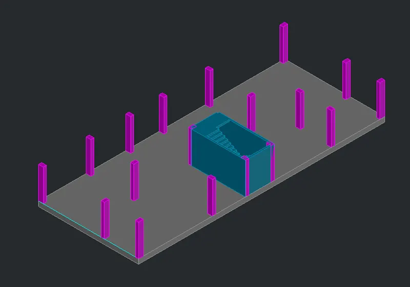
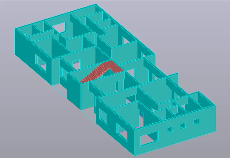
- Create a solid model of the ground floor parking plan
- Shift to the 3d modeling workspace by changing the settings available at the bottom right portion of the AutoCAD screen.
- At first, Create regions of the 2d plan.
- While creating the region, you can use boundary command and also region command, whichever works best according to the situation.
- While extruding, give the standard floor height as 10' which is generally adopted in the industry.
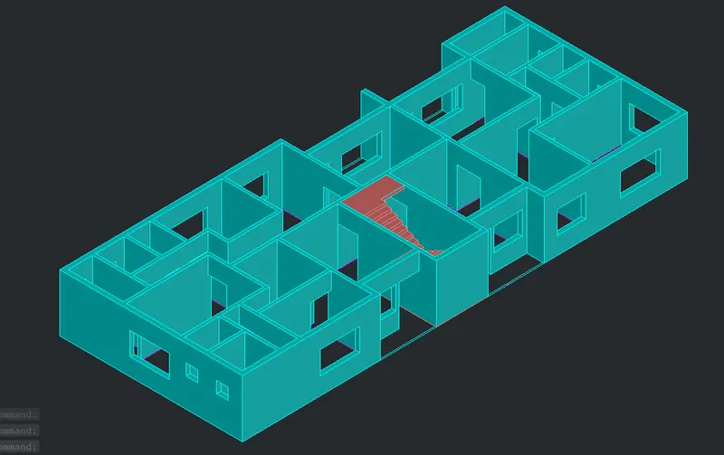
- Create a solid model of the typical floor plan.
- Type BO-> ENTER and select the region option in the dialogue box.
- Start creating the regional boundaries from the entire plan.
- After creating completing the boundary, use the extrude command.
- Give the standard floor height of 10 feet.
- Now, Create the openings for doors and windows by using the subtract command.
- Create the openings in rectangular shapes with accurate dimensions.
- Subtract the opening region from the entire face.
- Use the "UNION" command to make the entire solid floor one single entity.
- Create 3d solid models of the building openings that is doors and windows.
- Shift to the 2d model by typing plan and then double entering.
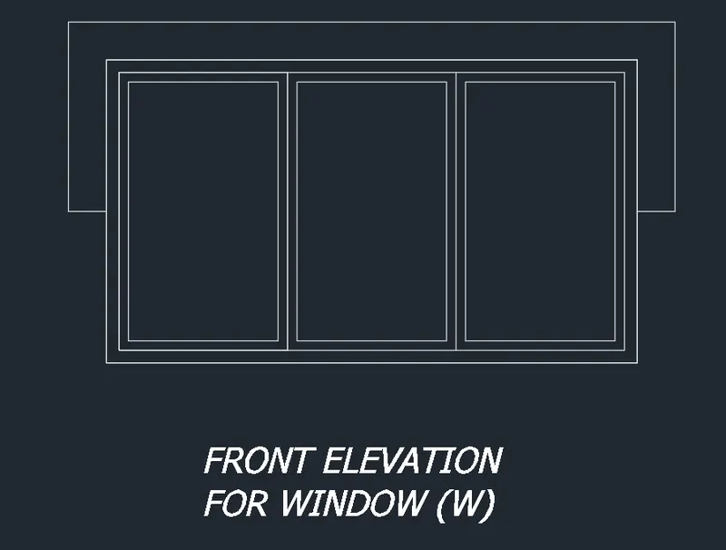
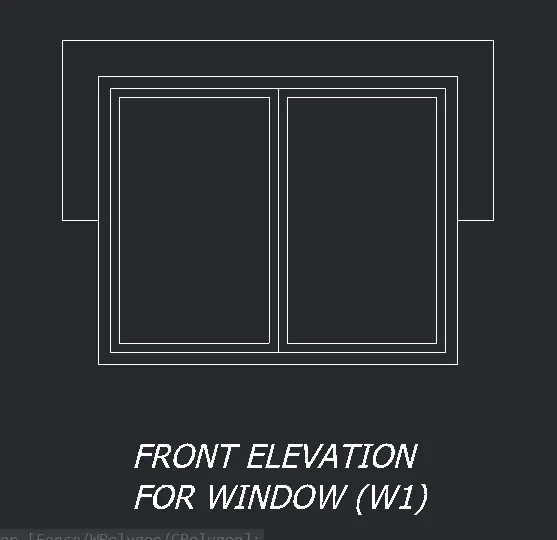
- Create the front elevation of the openings.
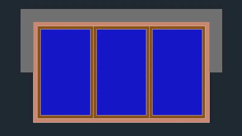
- Create regions out of the 2d front elevation of all doors and window types.
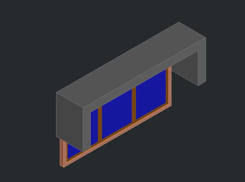
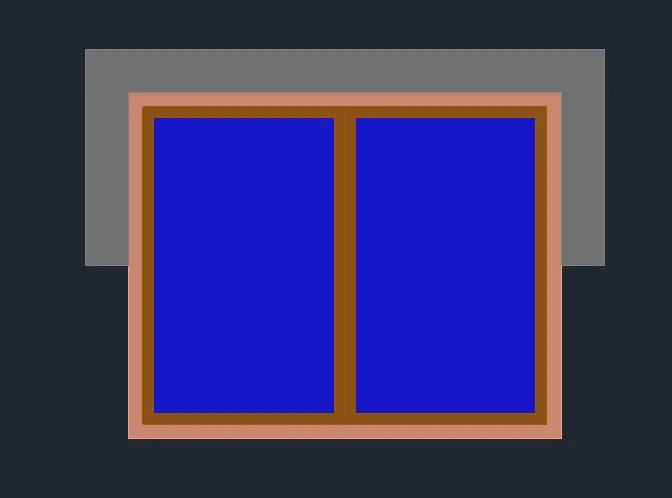
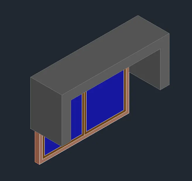
- Use the extrude command to transform the 2d front elevation into a 3d box model.
- Apply the same standard procedure for all objects.
- Window - W
2. Window - W1
3. Ventilator - V
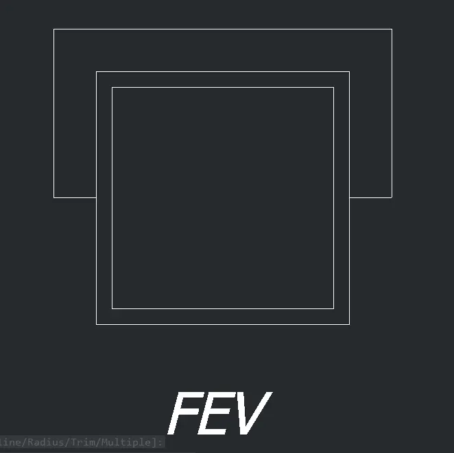
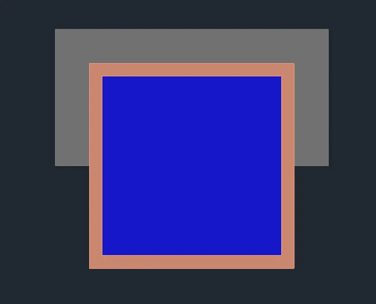
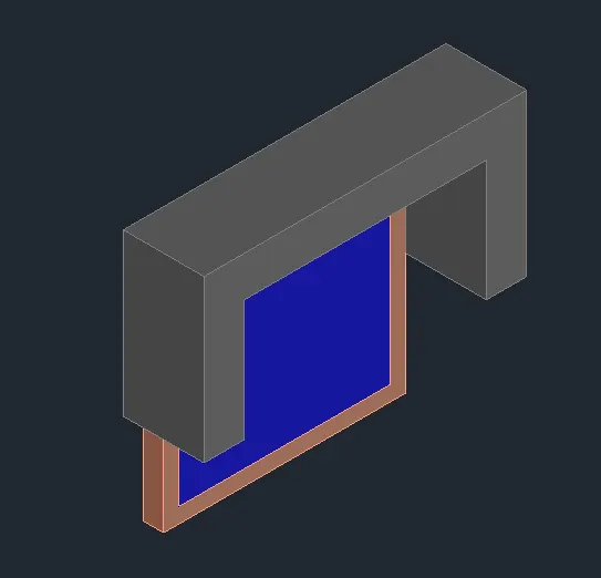
4. Door - D
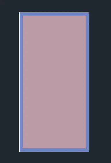
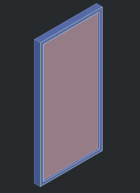
5. Door - D1
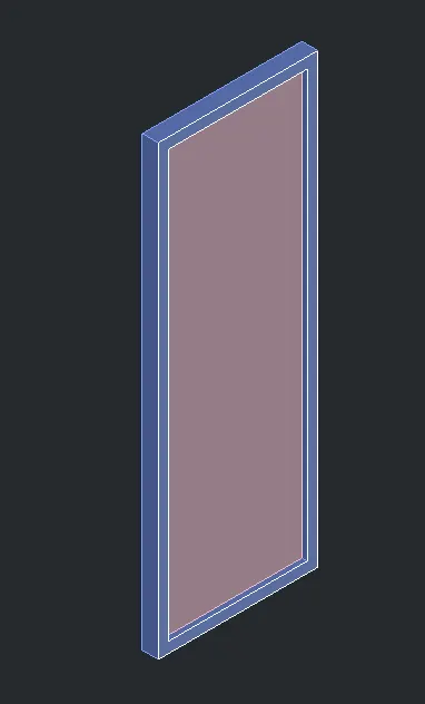
- Install the above created 3d models of all the windows and doors into the solid model of the typical floor plan.
- Select each object one piece at a time in the 3d workspace.
- Use to copy command and select the reference point wisely keeping in mind the current viewport.
- Select the reference point on the object and then on the floor model to place the doors and windows precisely.
- Puch back each object by 2 inches after placing to make it look more realistic.
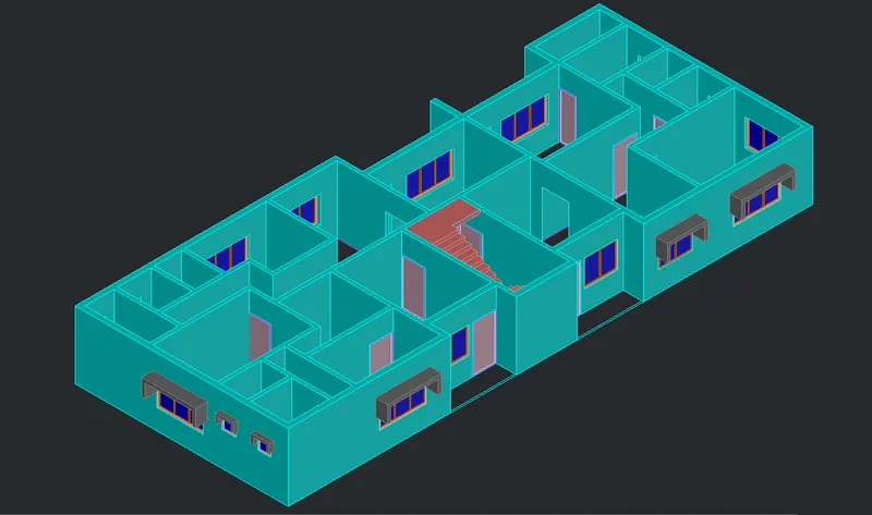
- Prepare the floor of the building.
- Type plan in the command panel and then double enter to shift into the 2d top view mode.
- Create a rectangle covering the entire typical floor plan of the building.
- Shift back to the 3d model by clicking on the home icon on the view cube.
- Use the "REG" command and select the rectangle to create a region out of it.
- Extrude it by 2 inches to create the flooring.
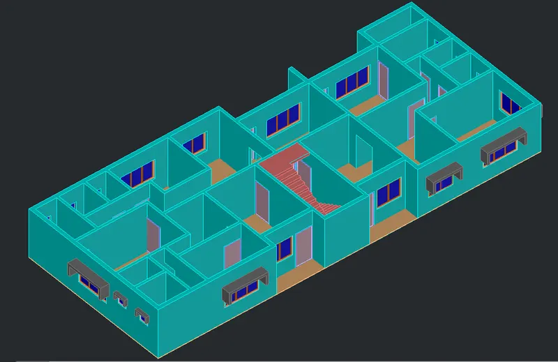
- Complete the 3d solid model of the proposed residential building.
- Select the final 3d floor plan and type CO-> ENTER to make copies out of it.
- Use the base point in the bottom left corner and paste it using the same on the bottom left corner in the parking lot model.
- Continue with the same procedure and complete the model for all four floors.
- Then, Extend the Staircase model onto the terrace plan and complete the same.
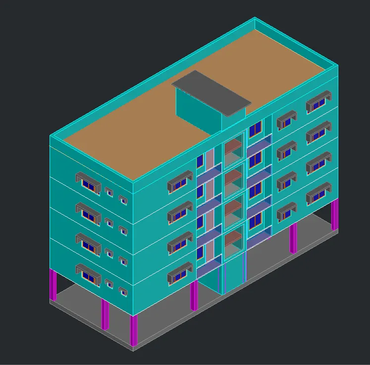
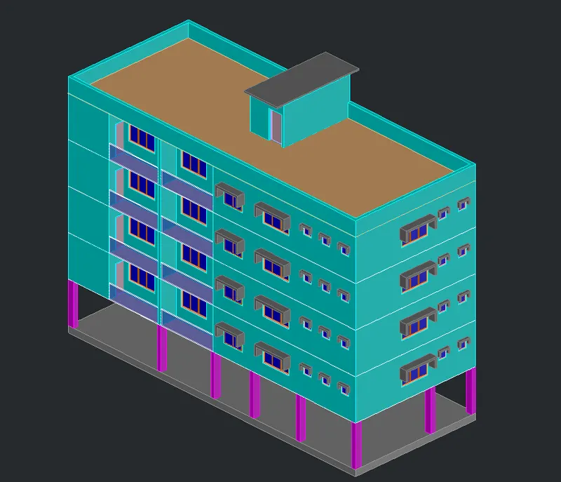
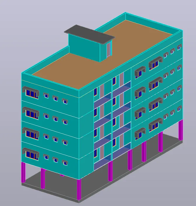
PHASE THREE (FINAL PHASE): Rendering the Building to Create the Realistic Visuals of the Completed Project.
STEPWISE PROCEDURE:
- Set up the camera views and create lights.
- Go to the visualize tab and click on the create camera option.
- Set up the camera location and then set up the specific target onto the building.
- Go to the settings and give the camera name, lens, shadow, and do other needed settings.
- Follow the same process to create two or more camera views.
- Now, create two to three distant lights and toggle between them to work the best effect.
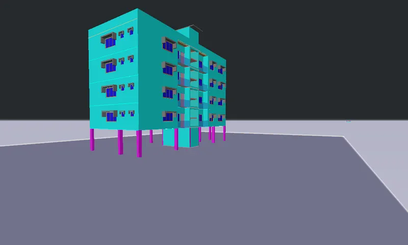
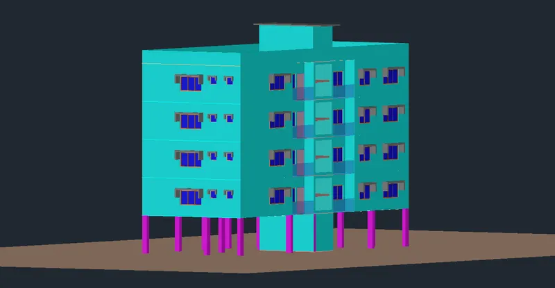
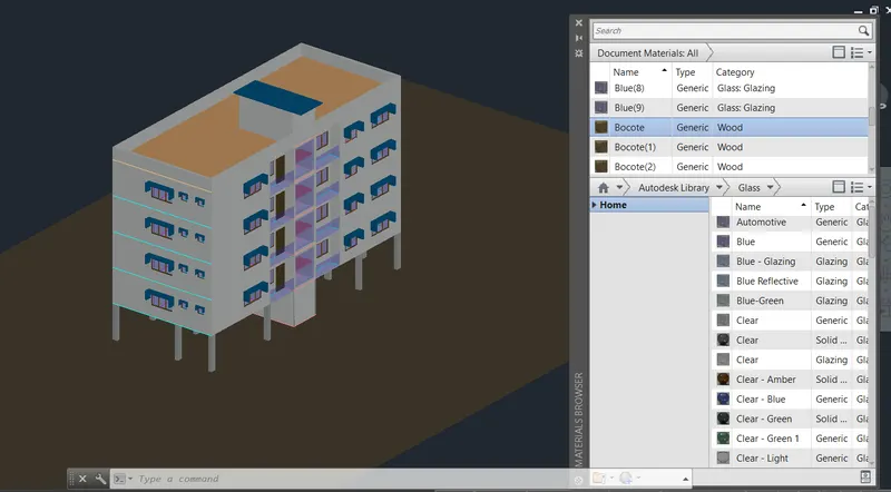
- Assign the material properties to the building.
- Type in "RMAT" in the command panel to open the material library.
- There are different materials categories like concrete, stone, glass, floor, wall paint, etc.
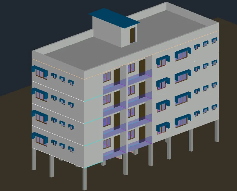
- Select the building component and assign the relevant material by right-clicking on the materials from the library.
- Follow the same procedure and complete the entire building model.
- Do the render settings to generate the render effects.
- Type in V-> ENTER and bring on the camera view.
- Go to the Visualize tab for settings purposes.
- Set up the shadow as the full shadow.
- Enable the sunlight.
- Switch on the sky and illumination adjacent to the sun.
- Go to the rendering panel to set up the environment and quality of the render.
- Use the accordant values for the environment, exposure, and other settings to generate more realistic outputs.
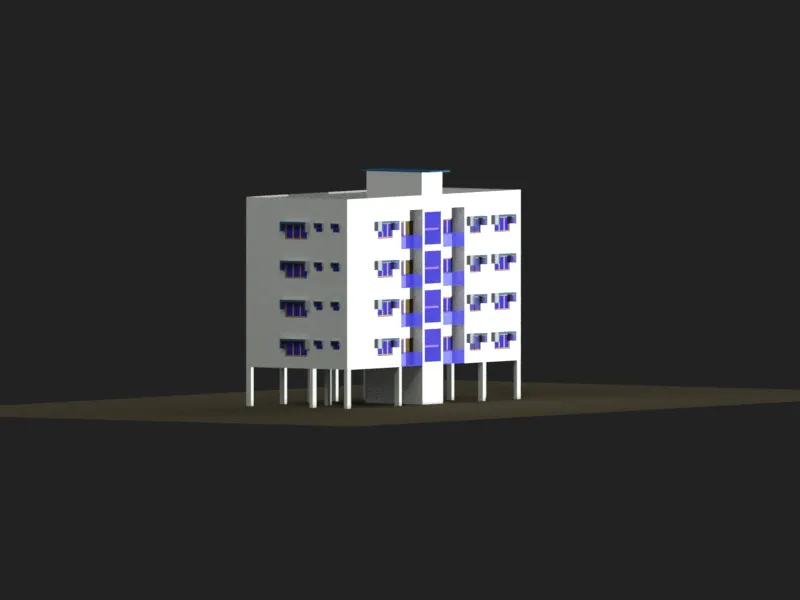
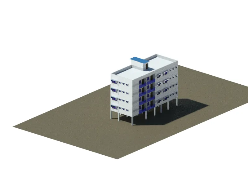
- Finally, type in "RR" to generate the rendered model of the building view.
- Use the same process to generate multiple models showcasing various features of the building.
CONCLUSION:
Thus, using AutoCAD, you can finish up the entire Architectural approach of a project starting from planning, drafting, to creating the full-fledged 3d models of the final building view upon its completion. All you have to do is know the exact commands, proper technique, and some fascination ability to create the real-time realistic visual effects of the proposed building be it a residential, commercial, hospital, institutional, industrial, or something else.