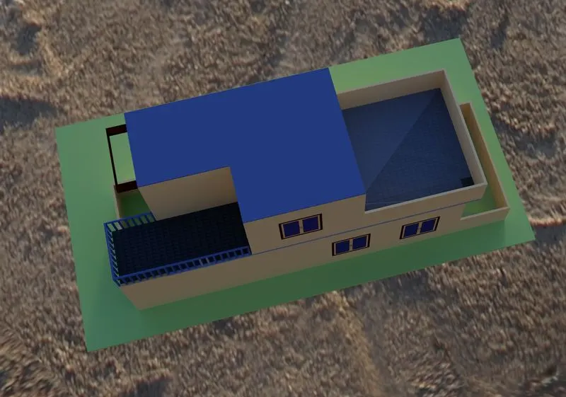
Project 2_Creating a 3D rendered model for a Residential Building in AutoCad
Q. Create a 3 dimensional model of the residential building with a rendered view.
AIM:
To create a 3 dimensional model of the residential building with a rendered view
PROCEDURE:
CREATION OF RESIDENTIAL BUILDING IN 2D
STEP 1: Setting units
- In command prompt type UNITS, set to ARCHITECTURAL, precision = 0'-0", insertion scale = INCHES
- In command prompt type LIMAX and LIMITS set to desired
- In command prompt type ZOOM, All and enter
STEP 2: PLAN
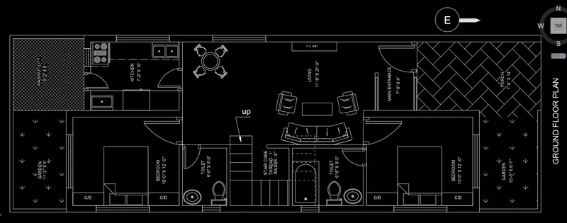
GROUND FLOOR
- In command prompt type REC, specify dimensions of length, width as 60',20'
- In command prompt type OFFSET, offset the lines as required of distance 4.5" and 9"
- In command prompt type BLOCK, create blocks of doors, windows and ventilators use where ever required
- In command prompt type DIML, assign dimensions where required
- In command prompt type DT, assign text
- In command prompt type ADC, select the required blocks from the AutoCAD center
- In command prompt type HATCH, hatch the area where required
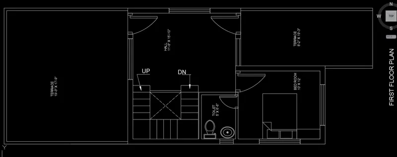
FIRST FLOOR PLAN
- In command prompt type COPY, copy the required details
- In command prompt type LINE, draw the lines where ever required
- In command prompt type TRIM, trim the unwanted lines
- In command prompt type OFFSET, offset the required lines
- In command prompt type DT, assign the text where required
STEP 3: CREATION OF 3D MODEL OF RESIDENTIAL BUILDING FROM 2D
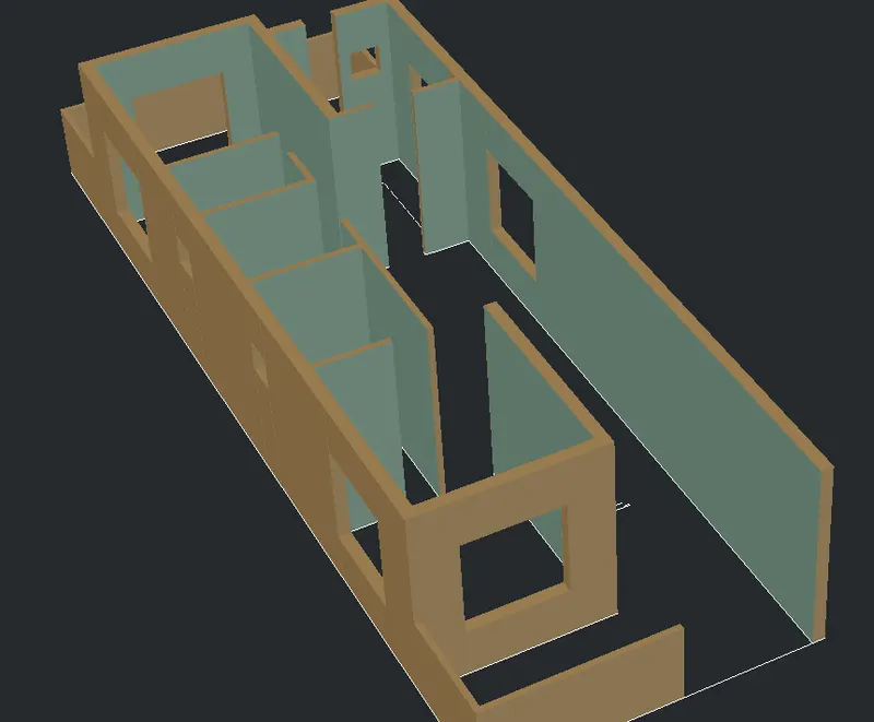
Creation of walls
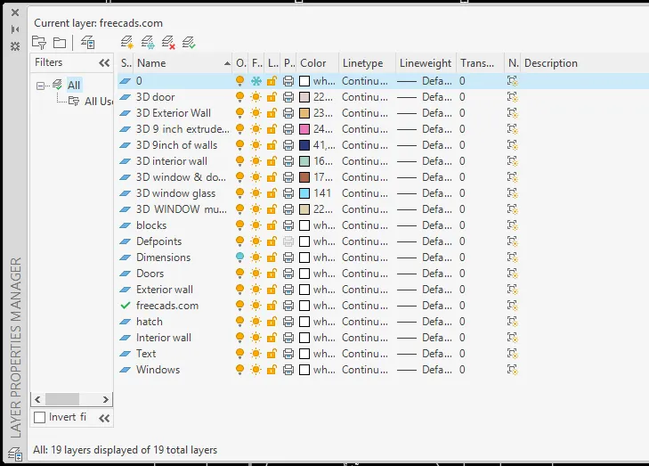
- In command prompt type LA, create the layers for 3d model
- In command prompt type BO, pick up the region or polylines
- In command prompt type REGION, select the regions
- In command prompt type EXTRUDE, extrude the selected regions to 12'
- In command prompt type LA, assign the layer to the extruded walls
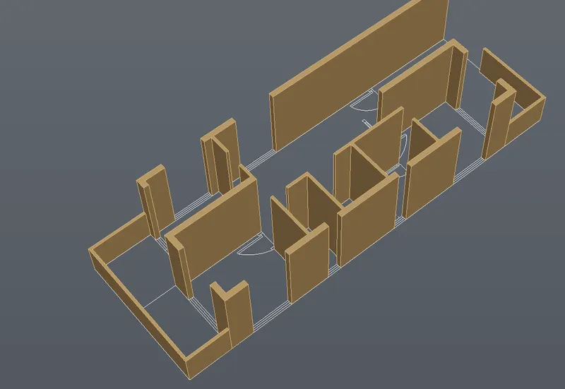
- In command prompt type UCS, specify the ucs for the creation of rec for windows, doors and ventilators up to sill level
- In command prompt type BO, pick up the region or polylines
- In command prompt type REGION, select the regions
- In command prompt type EXTRUDE, extrude the selected regions up to sill level that is 3'
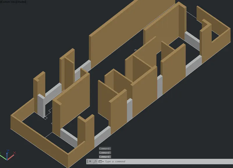
- In command prompt type UCS, specify the ucs for creation of top rectangle of windows, doors, and ventilators up to lintel level
- In command prompt type BO, pick up the region or polylines
- In command prompt type REGION, select the regions
- In command prompt type EXTRUDE, extrude the selected regions up to lintel level i.e., up to 3' from the top
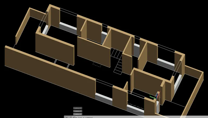
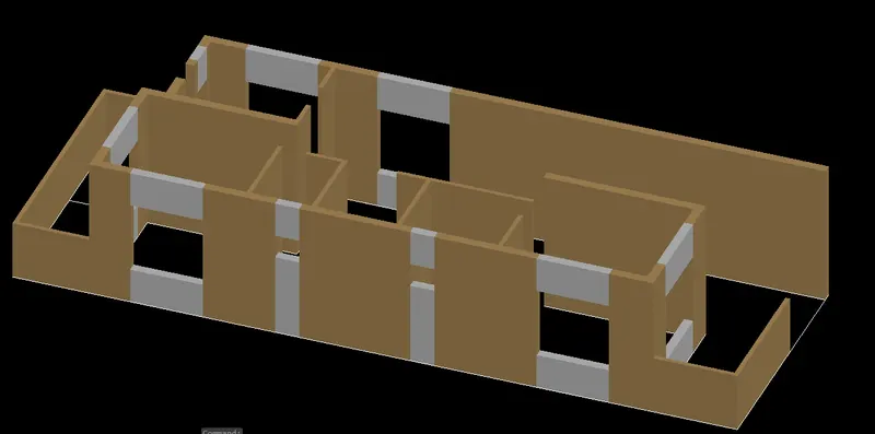
- In command prompt type UNION, select the created solids and union them
- In command prompt type LA, assign the layers to the newly created surfaces, solids
Creation of windows and ventilators
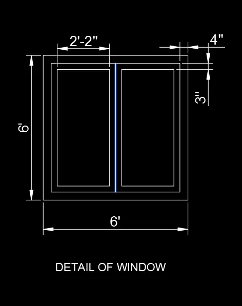
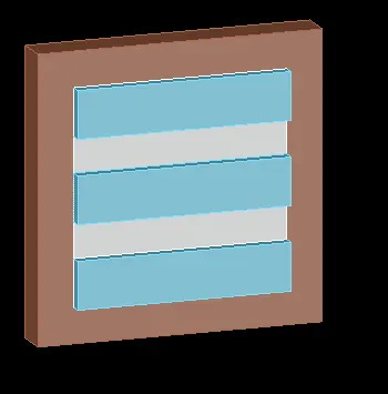
- In top view create the plan of the window
- In command prompt type REC, specify the dimensions of the rectangle of length, width as 6',6'
- In command prompt type OFFSET, offset the distance of 4" of the rectangle inwardly
- In command prompt type LINE, draw the midline with the help of object snap
- In command prompt type OFFSET, offset the inner line by the distance of 3" inwardly
- In command prompt type DIML, specify the dimensions
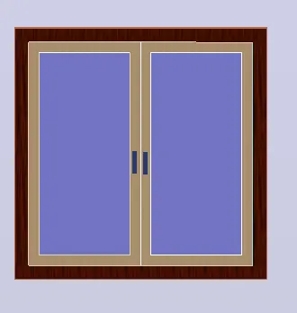
- In command prompt type 3DROTATE, rotate the plan of the window in front view
- In command prompt type BO, pick up the region or polylines
- In command prompt type REGION, select the regions
- In command prompt type SUBTRACT, subtract the smaller region from the bigger one i.e., window mullion from the window frame
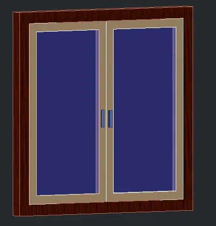
- In command prompt type EXTRUDE, extrude the remaining part that is a window frame
- In command prompt type LA, assign the layer to the window frame
- In command prompt type BO, pick up the region or polylines
- In command prompt type REGION, select the regions
- In command prompt type SUBTRACT, subtract the smaller region from the bigger one i.e., window glass from the window mullion
- In command prompt type LA, assign the layer to the window mullion
- In command prompt type LA, assign the layer to the window glass
- In top view create the plan of the VENTILATOR
- In command prompt type REC, specify the dimensions of the rectangle of length, width as 2',2'
- In command prompt type 3DROTATE, rotate the plan of the window in front view
- In command prompt type BO, pick up the region or polylines
- In command prompt type REGION, select the regions
- In command prompt type SUBTRACT, subtract the smaller region from the bigger one i.e., ventilator glasses region from frame
- In command prompt type LA, assign the layer to the frame
- In command prompt type REC, create rectangles for glasses
- In command prompt type LA, assign the layer to the frame
- In command prompt type EXTRUDE, extrude the frame and glass as per required
ASSIGN OF WINDOWS AND VENTILATORS ITO THE VOIDS:
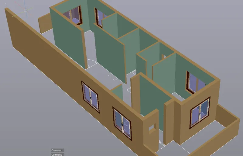
- In command prompt type COPY, copy the window frames as required
- In command prompt type MOVE, move the window frames with the help of snap object, and place them where ever required
- In command prompt type COPY, copy the ventilator frames as required
- In command prompt type MOVE, move the ventilator frames with the help of snap object, and place them where ever required
Creation of doors and staircase
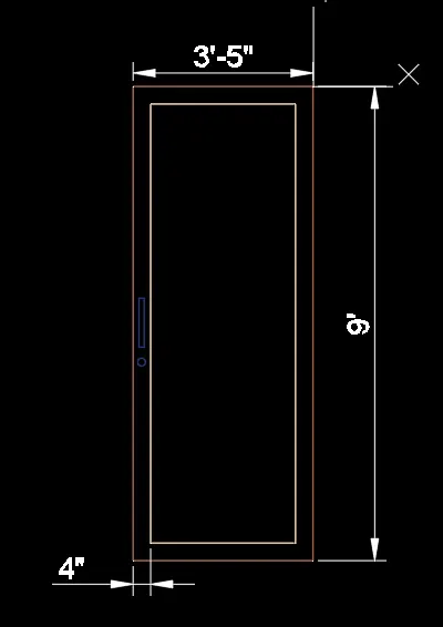
- In top view create the plan of the DOOR
- In command prompt type REC, specify the dimensions of the rectangle of length, width as 3'-5", 9'
- In command prompt type OFFSET, offset the distance of 4" of the rectangle inwardly
- In command prompt type DIML, specify the dimensions
- In command prompt type
- In command prompt type 3DROTATE, rotate the plan of the window in front view
- In command prompt type BO, pick up the region or polylines
- In command prompt type REGION, select the regions
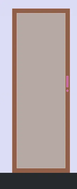
- In command prompt type SUBTRACT, subtract the smaller region from the bigger one i.e., inner frame region from the outer frame
- In command prompt type EXTRUDE, extrude the frame and inner frame as per required thickness
- In command prompt type LA, assign the layer to the inner and outer frames
STAIRCASE
- In command prompt type PLINE, create the staircase by pline of thread, raiser and landing are 1', 10", 6'-4"
- In command prompt type SWEEP, by selecting the object and path sweep of stairs are created
- In command prompt type LA, assign the layer to the created staircase
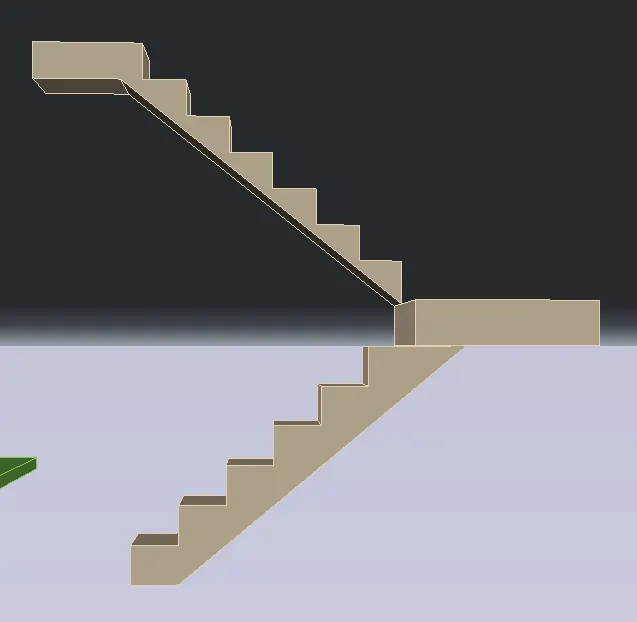
Assign the created doors and staircase
- In command prompt type COPY, copy created door frames as required
- In command prompt type MOVE, move the door frames with the help of snap object, and place them where ever required
- In command prompt type MOVE, move the staircase with the help of snap object, and plan
- In command prompt type REC, create the outer boundary in rectangle form
- In command prompt type EXTRUDE, extrude the created rectangle by 3" downward
- In command prompt type LA, assign the layer to the created rectangle
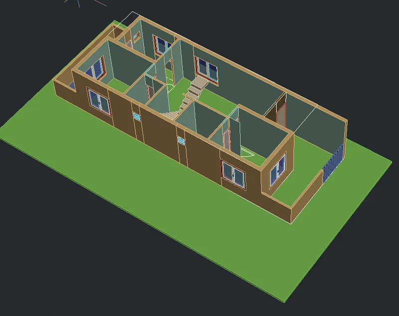
Creation of the First floor
- From the plan of the first floor in top view, walls are created
- In command prompt type BO, pick up the region or polylines
- In command prompt type REGION, select the regions
- In command prompt type EXTRUDE, extrude the selected regions by 12' for the walls
EXTRUSION OF WALLS FOR WINDOWS, DOORS, AND VENTILATORS
- In command prompt type UCS, specify the ucs for the creation of rec for windows, doors, and ventilators up to sill level
- In command prompt type BO, pick up the region or polylines
- In command prompt type REGION, select the regions
- In command prompt type EXTRUDE, extrude the selected regions up to sill level that is 3'
- In command prompt type UCS, specify the ucs for creation of top rectangle of windows, doors, and ventilators up to lintel level
- In command prompt type BO, pick up the region or polylines
- In command prompt type REGION, select the regions
- In command prompt type EXTRUDE, extrude the selected regions up to lintel level i.e., up to 3' from the top
- In command prompt type INSERT, select the window, doors, and ventilator blocks
- In command prompt type COPY, copy the blocks as many as required
- In command prompt type MOVE, move the blocks with the help of snap object, and place them in the voids
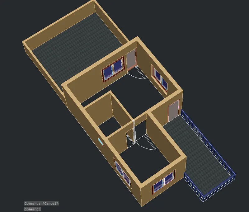
- In command prompt type REC, create a rectangle at top of the ground floor walls
- In command prompt type EXTRUDE, extrude the rectangle by 2" that looks like a slab
- In command prompt type MOVE, move the created first floor 3d model to the ground floor model with the help of a snap object
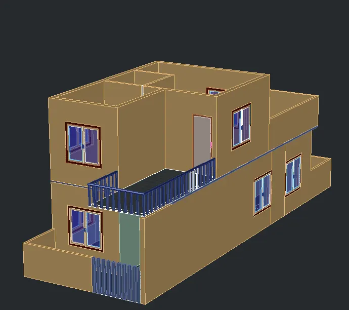
- In command prompt type REC, create a rectangle at top of the First-floor walls
- In command prompt type EXTRUDE, extrude the rectangle by 2" that looks like a slab
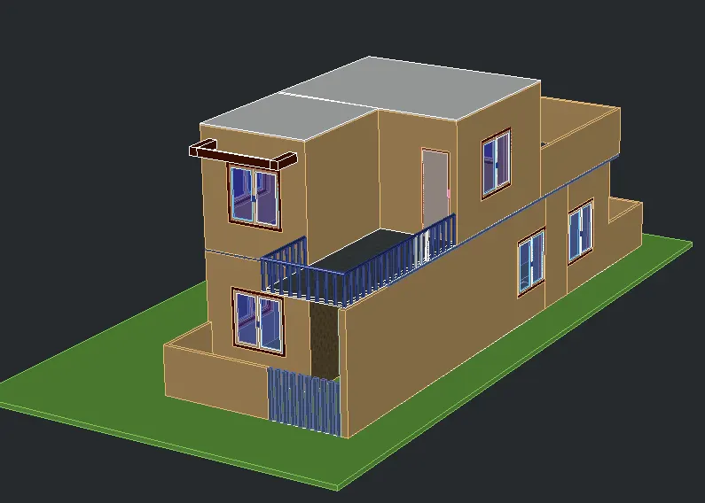
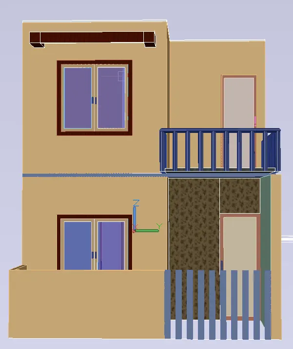
FRONT ELEVATION
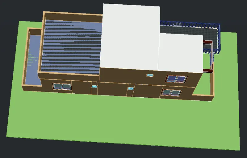
TOP VIEW OF THE BACKSIDE
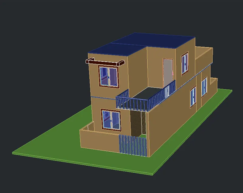
TOP VIEW FROM FRONT SIDE
STEP 4: RENDERING OF CREATED 3D MODEL
- In command prompt type RMAT, assign the materials as required where ever
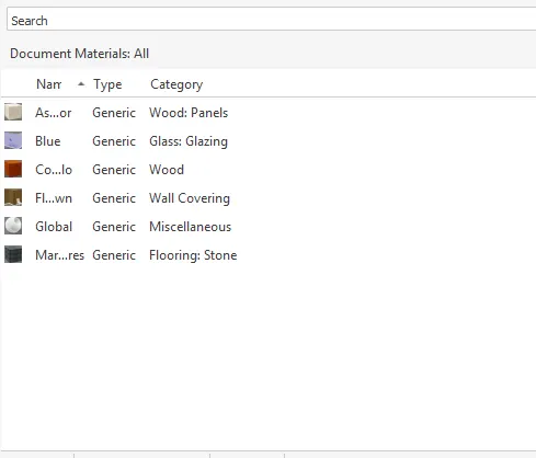
- In the ribbon, Visualize tab, select render panel, and assign the desired settings
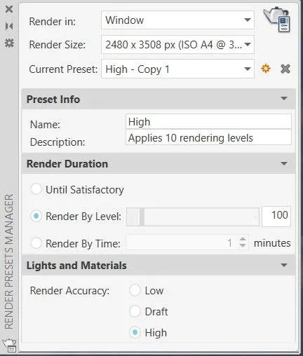
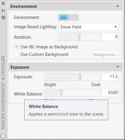
- After setup of the render details as desired quality
- In command prompt type RR, assign render
RESULT:
1. RENDERS FROM PC
FRONT ELEVATION
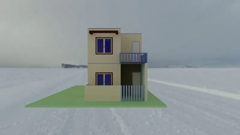
TOP VIEW
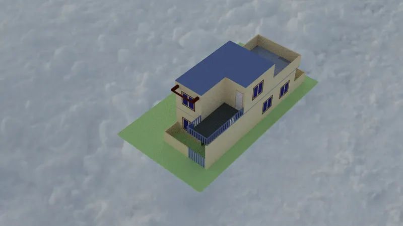
2. FROM CLOUD RENDERING
A.FRONT SIDE VIEW
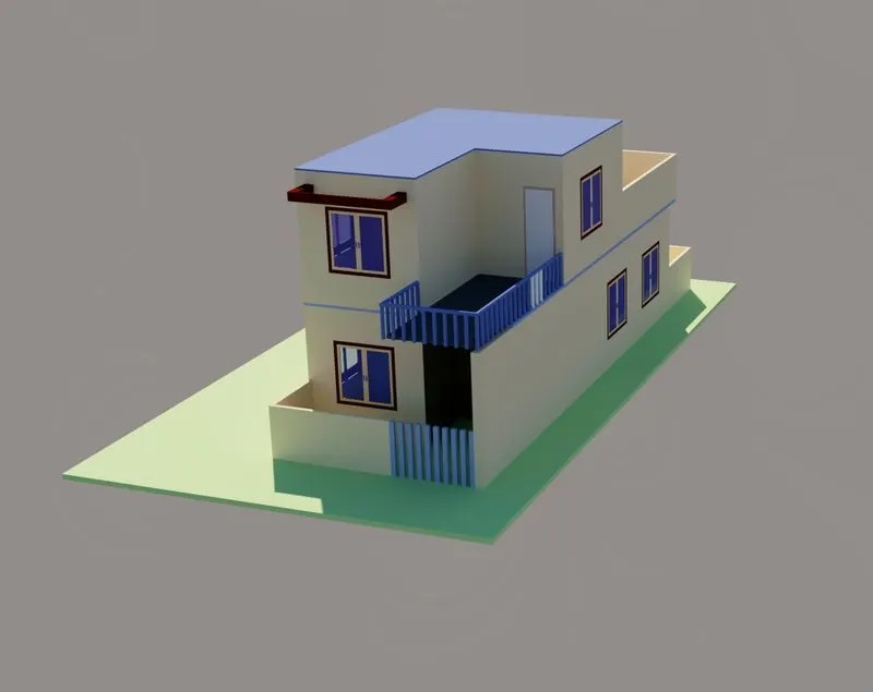
2. FRONT ELEVATION
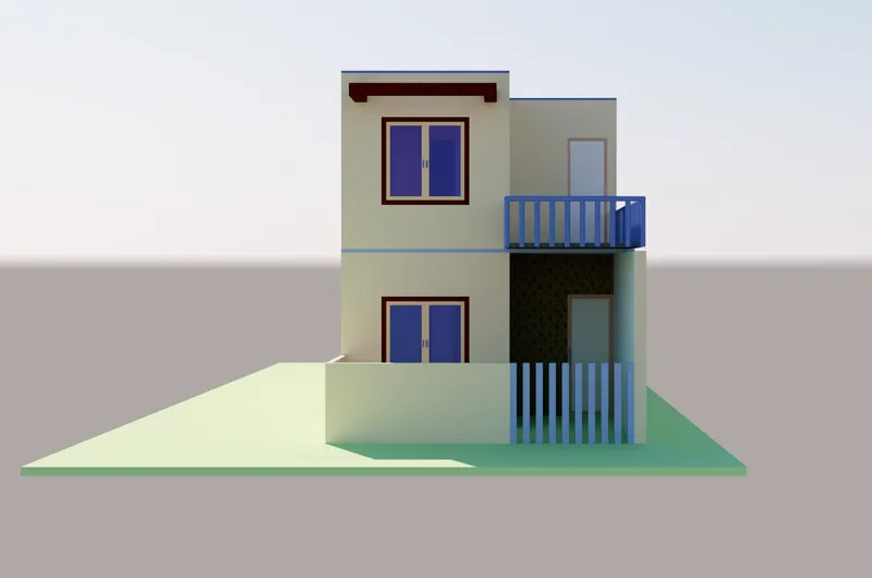
3. TOP VIEW WITH BEACH SIDE SCENE